Published by Tengku Juhana TENGKU HASHIM1, Azah MOHAMED2, Hussain SHAREEF3,
Universiti Kebangsaan Malaysia
Abstract. Power distribution systems are in the state of transition from passive to active networks due to the rising penetration level of distributed generators (DGs). One of the technical challenges of active networks is to maintain an acceptable voltage level. This problem has initiated many researchers to control network voltage profile. Several approaches to mitigate the voltage issues include the use of coordinated or centralized and decentralized methods. Both methods have been proven to be able to alleviate the voltage rise issue in distribution systems with DGs. This paper presents a literature review on the various voltage control methods that have been implemented in active distribution networks.
Streszczenie. Przy współpracujących sieciach rozproszonych problemem jest utrzymanie napięcia na pożądanym poziomie. W artykule przedstawiono przegląd różnych metod sterowania poziomem napięcia które moga być zastosowane w aktywnych sieciach rozproszonych. (Przegląd metod sterowania poziomem napięcia w aktywnych sieciach rozproszonych)
Keywords: Distributed Generator, active network, centralized and decentralized methods, voltage control.
Słowa kluczowe: sieci zasilające, sieci rozproszone, kontrola napięcia.
1. Introduction
The connection of DGs in distribution networks has created a challenge for distribution network operators (DNOs) to change their usual passive approach to an active system. This is due to the fact that the conventional distribution networks are designed based on the assumption of unidirectional power flow. With the increasing connection of DG, the network has become more dynamic with bidirectional power flow and it known as active distribution networks (ADN).
An active distribution network is defined as a distribution network with systems in place to control a combination of distributed energy resources comprising of generators and storage [1]. In [2], ADN is defined as a new system that adopts integration of control and communication technologies such that distribution network operators can manage and accommodate the new distribution network. The working group CIGRE C6.11 on the development and operation of active distribution networks has reported on the strengths and weaknesses of AND [1]. Some of the highlighted strengths are automation and control which will lead to improved network access for load customers. ADN will also provide increased operational reliability in terms of power delivery. However, there are some weaknesses which are associated with ADN such as maintenance issue, present lack of experience, and existing communication infrastructure.
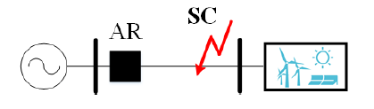
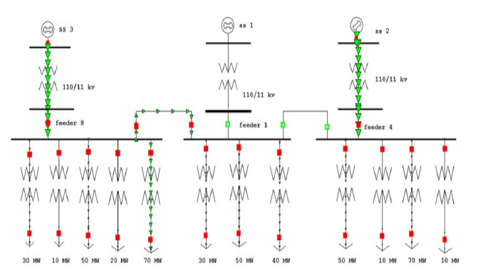
Some of the impacts and challenges addressed in the implementation of distribution networks with the presence of DGs include voltage levels and power flow, equipment thermal ratings, fault current levels and also protection issues [3]. With all these issues arising, an active network management (ANM) scheme is essential to provide coordination to power system operation. According to [4], ANM is defined as the use of real-time control and communication systems to provide a means to better integrate renewable distributed generators. With the increasing number of DG penetration, the issue of voltage level in distribution systems has become important. Increasing the number of connected generators will result in voltage rise above its permissible level [5]. The voltage rise effect due to the connection of a DG is illustrated by using a simple circuit shown in Figure 1. In this simple system, the generator, G with generation PG, QG together with local load, PL, QL and a reactive compensator, QC is connected to the distribution system through a weak rural overhead line with impedance Z and a transformer with an on load tap changer (OLTC).

From the figure, the voltage at busbar 2 (V2) can be approximately calculated as follows:
(1) V2 ≈ V1 + R (PG + PL) + (QG +QL + QC) X
This equation can be used to qualitatively analyze the relationship between the voltage at busbar 2 and the amount of generation that can be connected, as well as the impact of the alternative control actions to manage voltage rise [6].
The voltage rise is more severe when there is no demand due to the fact that all the local generation is exported back to the primary substation. Basically, there are two types of voltage issues which can be categorized as short term and long term voltage problems in distribution systems [7]. The short term voltage problem is usually caused by voltage sag or dip which is defined as a drop in voltage at a duration between one half-cycle and sixty seconds [8]. It is generally caused by a fault in the power system [8]. In contrast, overvoltage or undervoltage can be considered as a long term voltage problem which can lead to a more serious problem to power systems. The overvoltage problem calls for a management scheme that could alleviate the excessive voltage rise issues.
2. Voltage Control Methods with Distributed Generation
Current ANM schemes may be categorized as centralized or also known as coordinated control, semi-coordinated and decentralized control strategies. Centralized or coordinated control strategy provides voltage regulation from the substation to the rest of the network, potentially using a wide range of communication systems to coordinate different devices in the systems such as OLTC and voltage regulator. On the other hand, the semi-coordinated and decentralized or distributed control strategies must be able to control the DG unit locally in an active manner while coordinating it with a limited number of other network devices. These approaches are able to improve the overall network performance with limited costs incurring due to lower need of communication systems [9]. In the literature, a number of voltage control methods have been suggested to control voltage in the presence of DGs [7, 10, 11].
This paper presents a review of the voltage control methods associated with ADNs. In Section III, the centralized or coordinated voltage control methods will be discussed. Section IV reviews the decentralized voltage control methods with the presence of DGs. The methods that are discussed include the combination of power factor – voltage control method, reactive power compensation method, OLTC and generation curtailment. For decentralized voltage control in distribution systems, a review is made on the use of intelligent systems such as genetic algorithm, simulated annealing, Tabu search and multi agent system. Section V highlights on the issues and challenges associated with the management of ADNs, in particularly managing the increasing penetration of DGs in a distribution network. Table 1 illustrates the comparisons between centralized and decentralized methods where the advantages and disadvantages of both methods are shown and compared.
Table 1. Comparisons between centralized and decentralized voltage control methods
| Centralized methods | Decentralized methods |
| Wide coordination, requires communication | no coordination, limited communication |
| High cost | Cost saving |
| Extensive control | Local control |
For the aim of this review, a literature overview has been carried out including the IEEE/IET/Elsevier/Springer databases. The survey spans from the last decade, from the year 2000 until 2011. Figure 2 shows the statistical number of published research papers associated with voltage control methods in distribution networks with DG.

3. Centralized or Coordinated Voltage Control Schemes
The simplest active voltage level management methods are based on using local measurements and do not require additional data transfer between distribution network nodes. On the other hand, coordinated voltage control methods determine their control actions based on information about the whole distribution network and therefore data transfer between network nodes is required. There are quite a number of centralized or coordinated voltage controls in distribution systems that have been developed with different levels of complexity, effectiveness, communications requirements and investment costs. Examples of coordinated voltage management for distribution systems that have been identified includes centralized Distribution Management System(DMS) control and also coordination of distribution network components such as OLTC and switched capacitor control.
3.1 Distribution Management System Control
Distribution management system is an active management system where all the control decisions are made. DMS can be divided into basic and advanced DMSs. In basic DMS, simple decisions are made for disconnecting distributed energy resources in case of severe network conditions. However, advanced DMS involves using advanced control system which requires inputs such as status of the network, technical constraints and also market information on energy trades. This leads to the desirable outputs such as amount of generation curtailment and load shedding, ancillary services from DGs, network configuration and exploitation of storages [12]. In this work, the advanced DMS is developed using the classical optimal power flow concept, that is by finding the optimal combination of operations options. The aim is to minimize the operation costs due to energy losses, generation curtailment, reactive power and ancillary services, load shedding and energy storage while complying with the technical constraints.
In [6], the advanced DMS is considered as a sophisticated DMS which controls all components capable of voltage control through data transfer between network nodes. The substation voltage and reactive power of DG and also other components capable of voltage control are regulated in a coordinated voltage control system. The DMS developed in [6] is divided into two main parts, the hardware configuration and the controller software. An active management of the distribution system which makes use of an innovative controller that coordinates the OLTC action with the regulation of reactive exchanges between DG plants and feeders is also one of the voltage control methods suggested in [13]. To test the effectiveness of the proposed regulation, the DMS coordinated controller is applied to a realistic radial distribution network and the results proved that the capacity of DGs connected has improved significantly while maintaining the voltage profile in the system.
To further improve voltage regulation, the DMS will resort to generation curtailment when all other possible operation are unsuccessful [14]. In [15], optimization algorithm is applied to identify the most convenient DG units for injecting active and/or reactive power to minimize the amount of curtailed power. In [16, 17], DMSs which considers energy losses, line ampacity and contribution of responsive loads based on optimization of an objective function are applied for real time applications. The DMS which considers two new centralized control functions, the volt/var control and the optimal feeder reconfiguration is suggested in [18]. The work in [19] proposes a control logic for voltage regulation that integrates itself into the system which involves DG in the regulation process. Here, a coordinated control of transformer’s OLTC position, transformer voltage regulation mode and generator’s reactive power output are implemented using the algorithm developed based from real time data information. A power management system which uses state estimation algorithm coordinated with suitable voltage control equipment is discussed in [20]. Another method of voltage regulation using a power management system is carried out by using coordinated automatic voltage regulator and OLTC of Inter-bus transformers [21].
3.2 Coordination of Distribution Systems Components
The simplest and most studied method of coordinated voltage level management controls the substation voltage based on maximum and minimum voltages in the distribution network. These maximum and minimum voltages can be measured or estimated. The substation voltage is controlled by the changing the set point of the automatic voltage regulator relay which controls the tap changer of the main transformer.
Using control devices such as step voltage regulator and static VAR compensator (SVC), the voltage in a distribution system is able to be kept at its permissible level. SVC controls voltage by injecting reactive power, while step voltage regulator controls voltage by changing its tap position. Here, the centralized control calculates control variables by gathering data obtained by sensors at the distribution lines, so that the control devices are operated by the calculated control variables [22]. In [23], a control method was proposed by coordinating different devices such as the load ratio control transformer, step voltage regulator, shunt capacitor, shunt reactor and SVC. For state estimation, a segment controller utilizing OLTC is suggested by collecting local measurements of feeder loads, and key remote measurements of voltage and load, which form the inputs to the state estimator [24]. The generator automatic voltage control relay, is one of the innovative techniques used to improve voltage control and increase penetration of DGs. This method uses a state estimation technique in order to determine the voltage profile on the network and to adjust the voltage target for the automatic voltage control relay [25].
Reference [26] investigates the use of a voltage regulation method in the presence of DGs by implementing proper coordination among the OLTC, substation switched capacitors and feeder switched capacitors. A coordinated voltage regulation was suggested by combining the contribution of generator and the usage of the existing OLTC in providing voltage control to the distribution system [27]. A network voltage controller based on statistical state estimation algorithm is used to control the target voltage of the automatic voltage control relays at primary substations [28]. The state estimation algorithm estimates the voltage magnitude at each network node using real time measurement, network data and load data. In [29], an approach for coordinating voltage control for STATCOM and the under-load tap changer (ULTC) transformer is proposed. The ULTC transformer steps is being controlled so as to maximize the capacity margin of STATCOM, hence increasing the dynamic margin during system contingency situations as well as minimizes the number of tap changes. A coordination between step voltage regulator and DG operations for improvement of voltage profiles is suggested in [30], where the DG and the step voltage regulator are tested at different operating conditions. In [31], a control action coordination between OLTC and DG has been developed by utilizing the priority level of each regulating device through communication. The control zones of the regulating devices has also been developed using the sensitivity based technique.
By using contribution matrices which provide linear mapping of the variation of active and reactive powers of the distributed energy resources, appropriate control actions such as changing the tap changers of the transformer, controlling the reactive power and even generation curtailment can be done to bring the voltages of the critical nodes to an acceptable level [32]. Critical nodes are nodes in the network where the voltage is critical for the operation of the network. By using only measurements at the substation level and resemblance of the load patterns on the feeders, the technique of an advanced automatic voltage control relay called as the SuperTAPP n+ relay is able to estimate the output of a generator that is connected at a remote point on the feeder. It is also able to effectively control the target voltage according to the requirements [33].
3.3 Intelligent Centralized Methods
Intelligent techniques have been widely used to help solve issues associated with the planning of DG systems such as investment and operating cost minimization, capacity and siting of DG determination, coordination of voltage regulators and capacitors and also islanding of power systems with DG [34]. In this paper, voltage regulation issues are addressed using intelligent techniques including genetic algorithm (GA), Tabu search, artificial neural network (ANN), fuzzy logic, as well as multi agent system. Advantages of intelligent techniques are that it provides solution to voltage problems according to the varying condition and demand of the system. It also provides better solution compared to the conventional mathematical programming techniques, as it is more flexible in terms of cost functions and constraints and is also capable of handling nonlinear mixed integer programming problems [34]. However, the implementation of intelligent techniques requires some method of programming with more input data thus involving more complicated work to ensure its successful implementation. The method of using the reactive Tabu search in determining the coordinated allocation and control of step voltage regulators and SVCs has been presented in [35]. In [36], a GA based procedure is used to determine the optimal dispatch schedules for OLTC settings at substations and all shunt capacitor switching based on the day- ahead load forecast. The proposed strategy is proven to minimize power loss and improves the voltage profile. GA is also used for reactive power optimization problem in implementing a centralized reactive control scheme of grid-connected inverter in [37]. In [38], the fuzzy logic based voltage controller is implemented in both the centralized and also the decentralized schemes. In centralized or coordinated scheme, the fuzzy logic takes into account the average customer’s voltage as the input and the output as the preferred tap changer setting. Active network voltage regulation problem has also been mitigated by using the multi agent system [39]. Using the active and reactive power supports from DG and optimal tap setting of the OLTC, voltage control action is implemented autonomously within cells or feeders of the network. ANN is used to provide an intelligent predictive control technique for online management of reactive power from a group of DG units in [40]. The DG units are centrally controlled using one controller and was developed using two stage intelligent techniques. Combining the approaches of ANN and fuzzy logic system, a coordinated control for managing the main transformer ULTC and reactive power outputs from SVC is developed in [41]. In a related work, an ANN based control scheme for the management of ULTC transformer and STATCOM is discussed in [42]. By utilizing the active and reactive powers, tap position and STATCOM output, the voltage magnitude at the substation is maintained. The dispatchable DG is coordinated with the voltage control devices, namely the voltage regulators and capacitor bank using the Tabu search algorithm [43]. In [44], a new Tabu search algorithm for capacitor control in a distribution system is proposed. Capacitor control is essential in providing the means to adjust the nodal voltages from fluctuating.
4. Decentralized or Distributed Voltage Control Methods
Decentralized or distributed voltage control uses local information to independently control voltage at a particular bus where measurement, optimization and communication methods are usually limited. Different decentralized voltage control schemes have been studied to allow more DG capacity to be connected. Decentralized control has one major advantage compared to centralized control, that is, it is able to provide voltage support by controlling locally its operation modes. Hence, the problem of faults in communication lines and slow response to rapid voltage variations could be overcome [45]. Another advantage is cost saving since the decentralized control is able to improve the power systems performance while limiting the need for large investments on communication systems.
4.1 Reactive Power Compensation
Voltage rise caused by DG can be decreased by allowing the generator to absorb reactive power. Using synchronous generators, the control of reactive power is usually realized by an excitation system that consists of an AC or DC exciter, controller and voltage measurement components [46]. However, these generators have limitations on control of voltage and reactive power in distribution systems and therefore it requires additional compensating devices to ensure that the voltage level is acceptable. The applications of several end users or local compensation methods have proven to be a promising solution. These methods have several advantages in terms of efficiency, flexibility, reliability and scalability. A device such as STATCOM has the advantage of providing solution in fast response time, thus providing dynamic voltage control in the systems. On the other hand, SVC is able to provide voltage control within very tight parameters despite a widely varying load or contribution from DG [7]. The disadvantage of installing these reactive power compensating devices is the high costs of the devices.
A few reactive power compensation approaches for network with DG is discussed and compared in [47]. SVCs and STATCOMs are able to provide much better control on voltage profile when combined with fixed capacitor banks. Shunt capacitor banks is also another usual method for providing reactive power compensation in distribution systems. These devices consist of a number of large capacitors that can be connected or disconnected from the system by using switches. In this comparative study performed on different types of reactive power compensators, namely, single fixed capacitor bank, multiple-capacitor bank, SVC and STATCOM, simulation results have shown that SVC and STATCOM provide better voltage control in spite of the higher cost compared to the fixed capacitor bank. In [48], installing shunt reactance and increasing the cross-sectional area of the network conductors are the suggested methods to deal with voltage rise issue.
Several compensation devices have been installed in a distribution network, including a dynamic Var compensating device so as to reduce the voltage rise problem. Additional shunt reactors have also been used to help solve short and long term voltage issues. These devices provide voltage regulation and are used as part of an active network management scheme in the area of North Scotland [49]. Using the D-STATCOM as a voltage controller, the overall performance is proven to improve significantly. DSTATCOM has shown to be effective in compensating reactive power, balancing the load and elimination of harmonics [50]. A comprehensive study to evaluate the effectiveness of reactive power control in distribution networks using STATCOM devices have been conducted in [51]. Using unity power factor technique, a voltage control scheme has enabled the STATCOM to supply the reactive power requirements of wind farms generation, control the network voltage actively, hence, increasing the level of penetration of DG. An autonomous decentralized controller for voltage profile maintenance using reactive power control based on system connection inverter is proposed in [52]. The method is based on three control modes, “V-Ref method”, “Q-Save method”, and “Q-Coop method”, which operate based on voltage change in the system.
A local control scheme developed in [53] dispatches reactive power from each PV inverter based on local instantaneous measurements of the real and reactive components of the consumed power and the real power generated by the PV. Another distributed or decentralized reactive power generation control is suggested as an automatic control approach to manage the voltage rise issue caused by active power injection [54]. The reactive power control is linked to the operation of on OLTC to ensure that the active power generation does not cause voltage rise.
4.2 Power Factor-Voltage Control
Distribution network operators have traditionally required all DGs that are connected to the distribution network to operate in power factor control (PFC) mode [55]. The advantage of PFC is that it is less disruptive to the network devices such as OLTCs. However, the disadvantage of this method depends on a certain limit of generation connected to the system, whereby, a further increase in the generation will still result in voltage rise. The Power Factor Control – Voltage Control (PFC-VC) method combines the behaviour of the generator’s operation in two modes namely, constant power factor and voltage control. At normal conditions where the measured voltage is within the statutory upper and lower limits, the generator will operate in constant PFC mode. However, at times when the voltage deviates above or below the statutory limits, the generator will adopt the VC mode, that is, by varying the excitation of the automatic voltage regulator [56]. In the PFC mode, the real power over reactive power ratio is kept constant, with the reactive power following the variation of real power. In the VC mode, the automatic voltage controller is activated to vary excitation and move the operating point within the bus voltage limit. This method is implemented with the knowledge of combining the advantages of automatic voltage regulator and PFC and is also termed as automatic voltage/power factor control.
Independent producers adopt PFC strategy as a means to avoid penalties due to excessive reactive power consumption. In [4, 9, 57], the method is by increasing the input of generation to the distribution system while maintaining a fixed unity power factor operation. Other methods of voltage rise mitigation are combined with this PFC to tackle the voltage rise problem. In [58], three different modes of power factor operations is adopted by generators which is unitary, capacitive or inductive power factor depending on the regulatory operating rules. An adaptive PFC presented in [59] proved to be able to increase the generation capacity. This method is part of an active management scheme which has been implemented for maximizing wind power generation.
4.3 On load tap changer (OLTCs) scheme
The OLTC transformers are used between the multiple voltage levels to regulate and maintain the voltage which is supplied to consumers within statutory limits. The OLTC mechanism is a transformer component controlled automatically by a relay to increase or decrease voltage by altering the tap position of transformer [60]. When the secondary voltage detected is no longer within the permitted dead-band, the relay issues a command to the tap changer mechanism to alter its tap position in order to restore the required voltage level. The OLTC transformer, coupled with its automatic voltage control relay, regulates the transformer output voltage to keep the voltage magnitude within limits. One major disadvantage of this scheme is that the operation of the tap changer is limited to its tapping limits and capability.
However, with the presence of DG in the distribution networks, the automatic voltage control relay performance is affected, thus resulting in voltage regulation problems due to the interference. The DG integration changes the power flow and sometimes results in reverse power flow as well as a voltage increase occurring at the point of connection. The measured voltage is shifted upwards or downwards depending on the power factor of transformer current and direction of power flow to the DG and load [61]. A new voltage control methodology which controls the voltage control relays in OLTCs is proposed in [62]. This method deals with the problems associated with the connection of DGs such as inaccurate Load Drop Compensation (LDC), voltage level at the point of generator’s connection and impaired voltage control for paralleled transformers. The principles of operation of OLTCs with and without LDC together with the effect of DG on OLTC and LDC regulation has also been studied in [63]. With simulations on three different feeder models, the effectiveness of different regulation methods (LTC with reduced setting, LDC, DG with reactive power control capability and voltage regulator installation), was analyzed to show the dependency on feeder structure, parameters and DG connection point.
A control algorithm that controls the set point of the automatic voltage control relay at the substation is proposed in [64]. The proposed control algorithm works locally and is able to restore the substation voltage to an acceptable level and it does not cause continuous tapping of the tap changer in any situation. An Automatic Voltage Reference Setting (AVRS) technique which changes the voltage reference for the existing automatic voltage control relays is suggested in [65]. The AVRS works by measuring two or more essential voltages along the multiple feeders. From the results of minimum and maximum voltages obtained, the new voltage reference for automatic voltage control relay is then determined and the new technique is tested using a closed-loop testing facility based on the Real Time Digital Simulator. An advanced automatic voltage control relay called as the Transformer Automatic Paralleling Package schemes is presented in [66]. This method proved to be effective under varying power factor and load current without degrading the function of LDC, hence maintaining the transformers on a suitable tap position. In [67], a control algorithm that controls the set point of automatic voltage control relay at the substation is proposed. The control scheme managed to restore the voltage level based on information of local measurements without the continuous tapping of the tap changer. The Super Transformer Automatic Paralleling Package n+ relay scheme which is implemented based on locally taken measurements at the substation level combined with a state estimation technique is suggested in [68].
4.4 Generation Curtailment
Voltage rise can also be mitigated by reducing the active power output of DG. The main disadvantage of this method is that when a voltage limit is exceeded, only rarely the DG owner might find it beneficial to curtail some of its generation. This is due to the fact that curtailment will lead to losses in revenue [6]. The simplest method to implement generation curtailment is to disconnect the required number of generating units when the voltage exceeds its limits. For instance, if active power of DG can be controlled by blade angle control of wind generators, disconnection is not required as the active power of DG can be controlled continuously. In [4], the method is implemented to tackle the voltage rise problem as a last resort if the PFC –VC control mode is not successful. This scheme will reduce a given percentage of the power output when the voltage at the connection bus exceeds its statutory limits. The production of active power of low voltage photovoltaic generators is controlled by an innovative control logic in [69]. The aim of this control strategy is to increase the penetration limit of PV DG. However, an active control called as Power Curtailment, will adjust the active power generated according to the local node voltage to avoid overvoltage at the local node voltage.
In [15], it is suggested that when all the usual means of voltage control have been exhausted, generation curtailment can be used. The work concentrates on preventing voltage rises, as that tends to be the main problem with reverse power flows due to DG, but the methodology presented could also be used to manage curtailment in loads in the event of voltages dropping below its lower-statutory limit. As part of an active management method proposed in [59], the energy curtailment scheme was also tested to investigate the effect towards the amount of DG that could be connected. A droop based active power curtailment scheme for managing overvoltage issues is presented in [70-72]. Utilizing the droop control technique to manage the operation and power sharing among generators, an approach that results in equal sharing of output power losses among inverters is achieved.
4.5 Intelligent decentralized systems
Artificial neural network (ANN) scheme to manage voltage fluctuation is proposed in [73]. In this method, by analyzing the effects of reactive and active powers of DG on voltage profile, a decision support system based on ANN is developed. This is done by using the slope of voltage with respect to active and reactive power of DG unit to determine an appropriate bus to connect a DG thus reducing the voltage deviation of the critical bus. Hence, the voltage of the selected bus can be kept almost constant in terms of system operation. Another work which also utilizes ANN to manage the issue of voltage sag is presented in [74]. By using parameters from the distribution system that characterize voltage sags, the parameters are then calculated and compared to the required voltage magnitude, duration and phase angle to provide the required control action to regulate the terminal voltage at the busbar . ANN based approach has also been used in [75] to estimate the control parameters of STATCOM to improve voltage profile. Here, two ANNs have been developed simultaneously, for the estimation of STATCOM voltage magnitude and phase angle and also for the estimation of reactive powers in the STATCOM. In [76], the voltage controller of a generating unit in a distribution system is equipped with additional coordinated voltage controller which uses ANN. Here, the suggested ANN voltage control maintains the power system voltage profile hence reducing power system losses. An ANN based tap changer control was developed and presented in [42]. In this work, the tap operation was improved by exploitation of suitable output coding and ensemble principle. The ANN based automatic voltage control relay was proposed in [77]. Using a power system load flow program written in FORTRAN, the automatic voltage control relay is designed and implemented using ANN. In [45], ANN together with genetic algorithm are used to determine the optimal operation of the control devices such as step voltage regulator, shunt capacitor, shunt reactor, load ratio control transformer and SVC.
In [78], an evolutionary programming (EP) approach is applied for optimization of voltage control in distribution systems with DG. By using nested EP programming, the voltage deviations at the load nodes are minimized. In another research, the reactive Tabu search optimization method has been applied to determine fast optimal setting for transformers with voltage regulators and LDC to cope with the changes in the system [79]. Similarly, in [80], the Tabu search algorithm together with sensitivity analysis is implemented to provide reactive power compensation for wind farms. The component models of the wind farms and the objective function comprising of power losses, capacitor installation costs, bus voltage and wind turbines output constraints are considered in the work. Reactive power optimization based on the combination of ordinal optimization and Tabu search is proposed in [81]. In this optimization method, the mathematical modelling is done via two steps. The first step is to obtain a good initial solution for Tabu search via ordinal optimization followed by finding a global optimal solution using Tabu search. An intelligent voltage control for networks with DGs utilizing fuzzy logic is presented in [82]. The method suggests the use of local, intelligent and auto-adaptive voltage regulator for DGs which resulted in acceptable voltage levels in distribution systems on normal and emergency conditions. In [83], fuzzy logic is used to identify proper control actions for the distributed voltage controller sensors and oscillators aimed at improving the voltage level and reducing the power losses of the network. In [38], the concept of fuzzy logic is implemented in a decentralized way by controlling the setting of OLTC. The control action is based on the power flow information of the transformer hence limiting the need for communication. However, since this method depends on the network and load characteristics, fuzzy logic needs to be set up differently depending on the network load data analysis.
Multi agent system which is a system composed of multiple interacting agent systems has been applied to provide autonomous decentralized voltage control method for DGs [84]. The method which has been formulated considers the time delay with communications between the agents. In [85], a communication system using multi agent cooperative control structure has been suggested to solve voltage issues by utilizing the two way communication between components of static voltage regulator, feeder shunt capacitors and DG. In [86], a real time simulation of multi agent systems for a decentralized secondary voltage control is performed by combining two tools, the first one is a real time digital simulation for electric power simulation while the other one is a Java agent development framework. The multi agent approach is used to share voltage regulation effort and perform coordination of DG. Another decentralized multi agent voltage regulation approach presented in [87] is done by assigning each agent with a local multi-objective optimization function. This will control the voltage at its wind generator bus and participates in voltage regulation of pilot bus.
5. Issues and Challenges
Several issues and challenges have resulted due to increasing number of DG penetration in a distribution system, which forms the active network. An increased attention to active distribution networks can be seen to be motivated by three main reasons [88]. First, it is due to the increase in customers’ expectations in having a reliable power delivery and high quality of supply. Secondly, it is due to the desire in exploiting local renewable energy by facilitating the connection of small DG units into the medium and low voltage systems. The third reason is the strong desire in having a better management of assets from the view point of asset utilization, deferral of reinforcement and strategic replacement of aging assets by the distribution network operators. All these objectives would require further innovations in distribution systems in terms of providing a coordinated or active control across the power systems.
High penetration levels of DGs would raise several technical issues in a distribution system which includes voltage levels and power flow. Other rising issues include the issue of equipment thermal ratings, fault current levels and also protection issues [2]. The equipment thermal ratings might reach its limits if such high levels of DG penetration are connected to a distribution system. This is due to the fact that the total installed generation surpasses the local load, hence exporting back power to the main grid which would result in congestion of lines and failure of equipment thermal ratings. On the other hand, the fault current that flows in a network due to a fault in the system would also increase with the contribution from the DGs. The passive solution of installing equipment with higher level of ratings would again hamper the amount of DGs to be connected to the system due to rising costs. Protection issues are also another main problem and challenge in integrating an active distribution system. The technical experts and engineers must deal with several issues such as fuse and switchgear coordination, tripping, protection of relays, equipment ratings and islanding operations [89].
The economic and environmental major policy issues would also rise with further integration of DGs in the system [90]. High financial costs and economic efficiency are one of the major concerns in having higher level of DGs. This is due to the fact that the differences in capital costs between different DG technologies are quite large. The issue of environmental protection has also been raised. This is from the point of view of fuel utilization, whereby smaller DG plants are less efficient than larger central plants of the same type. The emission from the combined heat and power generation units are also one of the major concerns to the safety of the environment. Therefore, the outcome in terms of economic and environmental efficiency of different types of DG will differ with different DG technologies used. All these issues have received high level of attention among researchers and solutions and mitigation strategies have been proposed, experimented and implemented in the distribution system to provide a more stable power network.
6. Conclusions
This paper presents a review on the work that has been done with regards to voltage control methods implemented in the distribution systems connected with DGs. Various coordinated and distributed voltage regulation methods are overviewed and classified based on their control actions. Centralized or coordinated control methods are classified into three main categories, distribution management system, coordination of distribution system components and intelligent techniques. All these voltage control methods require high level of communication between the components of the system, thus incurring high costs in its implementation. However, the outputs of these type of voltage management proves to be more systematic and robust hence improving system operation significantly. On the other hand, the decentralized voltage control methods consider power factor control, reactive power compensation, OLTC, generation curtailment and also intelligent techniques that are based on local information with limited number of communication level between the network components. These methods do not provide solutions for the whole system, but still remains reliable depending on the control actions taken. Power – factor control methods proved to be reliable to a certain extent of DG inputs to the system, where increased DG level would result in voltage deviating from its permissible limit. Reactive power compensation is based on the idea that the generator is able to absorb the amount of excessive power to limit the voltage rise, but the main drawback of this reactive power absorption is loss increment. The amount of output power to be absorbed also depends on the generator’s capability. The OLTC scheme is limited by its tapping capability while the generation curtailment scheme is the last option to be implemented. The intelligent technique utilizes different optimization methods to maximize the control actions of the system’s components in managing power quality issues. All these methods which have been discussed and presented, provides voltage control support in distribution systems with DGs in their own unique way, depending on the situation and demand.
REFERENCES
[1] D’Adamo C.,Samuel J., and Chad A., Global survey on planning and operation of active distribution networks – Update of CIGRE C6.11 working group activities, 20th International Conference and Exhibition on Electricity Distribution – Part 1, (2009), 1-4.
[2] Hidalgo R., Abbey C., Joo, x, and s G., A review of active distribution networks enabling technologies, IEEE Power and Energy Society General Meeting (2010), 1-9.
[3] Jenkins N., Allan R.,Crossley P. , Kirschen D., Strbac G., Embedded Generation: The Institution of Electrical Engineers, London, 2000.
[4] Sansawatt T., Ochoa L. F., and Harrison G. P., Integrating distributed generation using decentralised voltage regulation, IEEE Power and Energy Society General Meeting (2010), 1-6.
[5] Masters C. L., Voltage rise: the big issue when connecting embedded generation to long 11 kV overhead lines, Power Engineering Journal, 16 (2002) No.1, 5-12.
[6] Strbac G., Jenkins N., Hird M., Djapic P. , Nicholson G., Integration of Operation of Embedded generation and distribution networks, University of Manchester Institute of Science and Technology (UMIST) 2002.
[7] O’Gorman R. and Redfern M. A., Voltage control problems on modern distribution systems, IEEE Power Engineering Society General Meeting, Vol.1 (2004), 662-667.
[8] IEEE Recommended Practice for Monitoring Electric Power Quality, IEEE Std 1159, (1995).
[9] Sansawatt T., O’Donnell J., Ochoa L. F., and Harrison G. P., Decentralised voltage control for active Distribution Networks, Proc. of the 44th International Universities Power Engineering Conference (UPEC) (2009), 1-5.
[10] T.Xu P.C. Taylor, Voltage Control Techniques for Electrical Distribution Networks including Distributed Generation, The International Federation of Automatic Control 17th World Congress (2008).
[11] Mutale J., Benefits of Active Management of Distribution Networks with Distributed Generation, IEEE PES Power Systems Conference and Exposition (2006), 601-606.
[12] Pilo F., Pisano G., and Soma G. G., Advanced DMS to manage active distribution networks, IEEE Bucharest PowerTech (2009), 1-8.
[13] Fabio B., Roberto C., and Valter P., Radial MV networks voltage regulation with distribution management system coordinated controller, Electric Power Systems Research, 78 (2008) No.4, 634-645.
[14] Kupzog F., Brunner H., Pruggler W., Pfajfar T., and Lugmaier A., DG DemoNet-Concept – A new Algorithm for active Distribution Grid Operation facilitating high DG penetration, 5th IEEE International Conference on Industrial Informatics, 2 (2007), 1197-1202.
[15] Zhou Q. and Bialek J. W., Generation curtailment to manage voltage constraints in distribution networks, IET Generation, Transmission & Distribution, 1 (2007) No.3, 492-498.
[16] G. Celli M. Loddo, F. Pilo, Distribution Network Planning with Active Management, 6th World Energy System Conference (2006).
[17] G. Celli, Pilo F., Pisano G., Soma G.G., Optimal planning of active networks, 16th Power Systems Computation Conference (2008).
[18] Roytelman I. and Ganesan V., Coordinated local and centralized control in distribution management systems, IEEE Transactions on Power Delivery, 15 (2000) No.2, 718-724.
[19] Conti S., Innovative Voltage Regulation Method for Distribution Networks with Distributed Generation, 19th International Conference on Electricity Distribution (2007),
[20] Hazel T. G., Hiscock N., and Hiscock J., Voltage Regulation at Sites With Distributed Generation, IEEE Transactions on Industry Applications 44 (2008) No.2, 445-454.
[21] Ran L., Spinato F., Taylor P., Wilson R., and Jackman D., Coordinated AVR and tap changing control for an autonomous industrial power system, IEE Proceedings on Generation, Transmission and Distribution, 153 (2006) No.6, 617-623.
[22] Hiroyuki H., Kobayashi H., A Study of Centralized Voltage Control Method for Distribution System with Distributed Generation, 19th International Conference on Electricity Distribution (2007).
[23] Senjyu T., Miyazato Y., Yona A., Urasaki N., and Funabashi T., Optimal Distribution Voltage Control and Coordination With Distributed Generation, IEEE Trans on Power Delivery, 23 (2008) No.2, 1236-1242.
[24] Thornley V., Jenkins N., Reay P., Hill J., Barbier C., Field Experience with Active Network Management of Distribution Networks with Distributed Generation, 19th International Conference on Electricity Distribution (2007).
[25] Thornley V., Hill J., Lang P., and Reid D., Active network management of voltage leading to increased generation and improved network utilisation, IET-CIRED Seminar on SmartGrids for Distribution (2008), 1-4.
[26] Viawan F. A. and Karlsson D., Coordinated voltage and reactive power control in the presence of distributed generation, IEEEPower and Energy Society General Meeting – Conversion and Delivery of Electrical Energy in the 21st Century (2008), 1-6.
[27] Caldon R., Spelta S., Prandoni V., Turri R., Coordinated Voltage Regulation in Distribution Networks with Embedded Generation, 18th International Conference on Electricity Distribution (2005).
[28] Hird C. M., Leite H., Jenkins N., and Li H., Network voltage controller for distributed generation, IEE Proc on Generation, Transmission and Distribution, 151 (2004) No.2, 150-156.
[29] El Moursi M. S., Bak-Jensen B., and Abdel-Rahman M. H., Coordinated Voltage Control Scheme for SEIG-Based Wind Park Utilizing Substation STATCOM and ULTC Transformer, IEEE Trans on Sustainable Energy, 2 (2011) No.3, 246-255.
[30] Kojovic L. A., Coordination of distributed generation and step voltage regulator operations for improved distribution system voltage regulation, IEEE Power Engineering Society General Meeting (2006).
[31] Le A. D. T., Muttaqi K. M., Negnevitsky M., and Ledwich G., Response coordination of distributed generation and tap changers for voltage support, Australasian Universities Power Engineering Conference (2007), 1-7.
[32] Viehweider A., Bletterie B., Burnier De Castro D., Advanced Coordinated Voltage Control Strategies for Active Distribution Network Operation, 20th International Conference on Electricity Distribution (2009).
[33] Fila M., Reid D., Taylor G. A., Lang P., and Irving M. R., Coordinated voltage control for active network management of distributed generation, IEEE Power & Energy Society General Meeting (2009), 1-8.
[34] Santoso S., Saraf N., and Venayagamoorthy G. K., Intelligent Techniques for Planning Distributed Generation Systems, IEEE Power Engineering Society General Meeting (2007), 1-4.
[35] Sugimoto J., Yokoyama R., Fukuyama Y., Silva V. V. R., and Sasaki H., Coordinated allocation and control of voltage regulators based on reactive tabu search, IEEE Russia Power Tech (2005), 1-6.
[36] Hu Z., Wang X., Chen H., and Taylor G. A., Volt/VAr control in distribution systems using a time-interval based approach, IEE Proceedings on Generation, Transmission and Distribution, 150 (2003) No.5, 548-554.
[37] Wang R.,Lin F.,You X., and Zheng T. Q., Research on the reactive power control of grid-connected inverter of distributed generation system based on genetic algorithm, 3rd IEEE Conference on Industrial Electronics and Applications (2008), 1096-1099.
[38] Shalwala R. A. and Bleijs J. A. M., Voltage control scheme using Fuzzy Logic for residential area networks with PV generators in Saudi Arabia, IEEE PES Innovative Smart Grid Technologies (ISGT) (2011), 1-6.
[39] Nguyen P. H., Myrzik J. M. A., and Kling W. L., Coordination of voltage regulation in Active Networks, IEEE/PES Trans and Dist Conf and Exposition (2008), 1-6.
[40] Wanik M. Z. C., Erlich I., Mohamed A., and Shareef H., Predictive var management of distributed generators, Conf Proc IPEC (2010), 619-624.
[41] Liang R.H. and Liu X.Z., Neuro-Fuzzy Based Coordination Control in a Distribution System with Dispersed Generation System, International Conference on Intelligent Systems Applications to Power Systems (2007), 1-6.
[42] Gwang W.K. and Lee K. Y., Coordination control of ULTC transformer and STATCOM based on an artificial neural network, IEEE Transactions on Power Systems, 20 (2005) No.2, 580-586.
[43] Ausavanop O. and Chaitusaney S., Coordination of dispatchable distributed generation and voltage control devices for improving voltage profile by Tabu Search, 8th International Conference on Electrical
Engineering/Electronics, Computer, Telecommunications and Information Technology (ECTI-CON) (2011), 869-872.
[44] Mori H. and Iimura Y., Dual tabu search for capacitor control in distribution systems, IEEE PES Power Systems Conference and Exposition, 3 (2004), 1434-1439.
[45] Toma S., Senjyu T., Miyazato Y., Yona A., Tanaka K., and Chul-Hwan Kim, Decentralized voltage control in distribution system using neural network, IEEE 2nd International Power and Energy Conference (2008), 1557-1562.
[46] Turitsyn K., Sulc P., Backhaus S., and Chertkov M., Local Control of Reactive Power by Distributed Photovoltaic Generators, First IEEE International Conference on Smart Grid Communications (2010), 79-84.
[47] Elnashar M., Kazerani M., El Shatshat R., and Salama M. M. A., Comparative evaluation of reactive power compensation methods for a stand-alone wind energy conversion system, IEEE Power Electronics Specialists Conference (2008), 4539- 4544.
[48] Caples D., Boljevic S., and Conlon M. F., Impact of distributed generation on voltage profile in 38kV distribution system, 8th International Conference on the European Energy Market (EEM) (2011), 532-536.
[49] Currie R. A. F., Ault G. W., Fordyce R. W., MacLeman D. F., Smith M., and McDonald J. R., Actively Managing Wind Farm Power Output, IEEE Transactions on Power Systems, 23 (2008) No.3, 1523-1524.
[50] Aggarwal M., Gupta S. K., Madhusudan M., and Kasal G., DSTATCOM Control in Low Voltage Distribution System with Distributed Generation, 3rd Int. Conf. on Emerging Trends in Engineering and Technology (ICETET) (2010), 426-429.
[51] Saad-Saoud Z., Lisboa M. L., Ekanayake J. B., Jenkins N., and Strbac G., Application of STATCOMs to wind farms, IEE Proc. on Generation, Transmission and Distribution, 145 (1998) No.5, 511-516.
[52] Tsuji T., Oyama T., Hashiguchi T., Goda T., Horiuchi K., Tange S., Shinji T., and Tsujita S., A study on autonomous decentralized voltage controller in distribution network considering control priority, International Conference on Clean Electrical Power (ICCEP) (2011), 749-754.
[53] Turitsyn K., Sulc P., Backhaus S., and Chertkov M., Options for Control of Reactive Power by Distributed Photovoltaic Generators, IEEE Proceedings, 99 (2011) No.6, 1063-1073.
[54] Carvalho P. M. S., Correia P. F., and Ferreira L. A. F., Distributed Reactive Power Generation Control for Voltage Rise Mitigation in Distribution Networks, IEEE Transactions on Power Systems, 23 (2008) No.2, 766-772.
[55] Vovos P. N., Kiprakis A. E., Wallace A. R., and Harrison G. P., Centralized and Distributed Voltage Control: Impact on Distributed Generation Penetration, IEEE Trans. on Power Systems 22 (2007) No.1, 476-483.
[56] Kiprakis A. E. and Wallace A. R., Maximising energy capture from distributed generators in weak networks, IEE Proc. on Generation, Transmission and Distribution, 151 (2004) No.5, 611-618.
[57] Thipnatee Sansawatt Luis F. Ochoa, Gareth Harrison, Decentralised Voltage and Thermal Management to enable more Distributed Generation Connection CIRED Workshop (2010),
[58] Freitas W., Vieira J. C. M., Morelato A., and Xu W., Influence of excitation system control modes on the allowable penetration level of distributed synchronous generators, IEEE Transactions on Energy Conversion, 20 (2005) No.2, 474-480.
[59] Ochoa Luis F., Andrew K., Chris D., and Harrison Gareth P., Applying active network management schemes to an Irish distribution network for wind power maximisation, 20th Int. Conf. and Exhibition on Electricity Distribution – Part 1 (2009), 1-4.
[60] Gao C. and Redfern M. A., A review of voltage control techniques of networks with distributed generations using On-Load Tap Changer transformers, 45th International Universities Power Engineering Conference (UPEC) (2010), 1-6.
[61] Thomson M., Automatic voltage control relays and embedded generation., Power Engineering Journal, 14 (2000) No.2, 71-76.
[62] Hiscock J., Hiscock N., Kennedy A., Advanced Voltage Control for Networks with Distributed Generation 19th International Conference on Electricity Distribution (2007),
[63] Viawan Ferry A., Sannino Ambra, and Daalder Jaap, Voltage control with on-load tap changers in medium voltage feeders in presence of distributed generation, Electric Power Systems Research, 77 (2007) No.10, 1314-1322.
[64] Kulmala A., Maki K., Repo S., and Jarventausta P., Including active voltage level management in planning of distribution networks with distributed generation, IEEE Bucharest PowerTech (2009), 1-6.
[65] Li H. Y. and Leite H., Increasing distributed generation using automatic voltage reference setting technique, IEEE Power and Energy Society General Meeting – Conversion and Delivery of Electrical Energy in the 21st Century (2008), 1-7.
[66] Fila M., Taylor G. A., Irving M. R., Hiscock J., Lang P., and Aston P., Systematic modelling and analysis of TAPP voltage control schemes, 42nd International Universities Power Engineering Conference (2007), 349-356.
[67] Kulmala A., Maki K., Repo S., and Jarventausta P., Active Voltage Level Management of Distribution Networks with Distributed Generation using On Load Tap Changing Transformers, IEEE Lausanne Power Tech (2007), 455-460.
[68] Fila M., Taylor G. A., Hiscock J., Irving M. R., and Lang P., Flexible voltage control to support Distributed Generation in distribution networks, 43rd International Universities Power Engineering Conference (2008), 1-5.
[69] Conti S., Greco A., Messina N., and Raiti S., Local voltage regulation in LV distribution networks with PV distributed generation, International Symposium on Power Electronics, Electrical Drives, Automation and Motion (2006), 519-524.
[70] Tonkoski R., Lopes L. A. C., and El-Fouly T. H. M., Coordinated Active Power Curtailment of Grid Connected PV Inverters for Overvoltage Prevention, IEEE Transactions on Sustainable Energy, 2 (2011) No.2, 139-147.
[71] Tonkoski R., Lopes L. A. C., and El-Fouly T. H. M., Droopbased active power curtailment for overvoltage prevention in grid connected PV inverters, IEEE International Symposium on Industrial Electronics (ISIE) (2010), 2388-2393.
[72] Tonkoski R., Lopes L. A. C., and Turcotte D., Active power curtailment of PV inverters in diesel hybrid mini-grids, Electrical Power & Energy Conference (EPEC), 2009 IEEE (2009), 1-6.
[73] Ugranli F., Ersavas C., and Karatepe E., Neural network based distributed generation allocation for minimizing voltage fluctuation due to uncertainty of the output power, International Symposium on Innovations in Intelligent Systems and Applications (INISTA) (2011), 415-419.
[74] Ipinnimo O., Chowdhury S., and Chowdhury S. P., ANN-based voltage dip mitigation in power networks with distributed generation, IEEE/PES Power Systems Conference and Exposition (PSCE) (2011), 1-8.
[75] Varshney S., Srivastava L., and Pandit M., ANN based control of Statcom for improving voltage profile in power system, India International Conference on Power Electronics (IICPE) (2011), 1-7.
[76] Gubina A. F., Gubina F., and Golob R., Intelligent coordinative voltage and reactive power control, International Journal of Electrical Power & Energy Systems, 23 (2001) No.4, 313-321.
[77] Salman S. K. and Rida I. M., ANN-based AVC relay for voltage control of distribution network with and without embedded generation, International Conference on Electric Utility Deregulation and Restructuring and Power Technologies (2000), 263-267.
[78] Batrinu F., Carpaneto E., Chicco G., De Donno M., Napoli R., Porumb R., Postolache P., and Toader C., New nested evolutionary programming approach for voltage control optimization with distributed generation, Proceedings of the 12th IEEE Mediterranean Electrotechnical Conference, 3 (2004), 1007-1010 Vol.3.
[79] Oomori T., Genji T., Yura T., Takayama S., Watanabe T., and Fukuyama Y., Fast optimal setting for voltage control equipment considering interconnection of distributed generators, IEEE/PES Asia Pacific Trans. and Dist. Conf. and Exhibition, 2 (2002), 1145-1150 vol.2.
[80] Ling L., Xiangjun Z., Ping Z., Yunfeng X., and Guopin L., Optimization of Reactive Power Compensation in Wind Farms Using Sensitivity Analysis and Tabu Algorithm, IEEE Industry Applications Society Annual Meeting (2008), 1-5.
[81] Haoming Liu, Yunhe Hou, and Xingying Chen, A hybrid algorithm of ordinal optimization and Tabu Search for reactive power optimization in distribution system, Third International Conference on Electric Utility Deregulation and Restructuring and Power Technologies (2008), 1318-1324.
[82] T.Tran-Quoc E.Monnot, G.Rami, A.Almeida, Ch.Kieny, N. Hadjsaid, Intelligent Voltage Control in Distribution Network with Distributed Generation, 19th International Conference on Electricity Distribution (2007),
[83] Loia V. and Vaccaro A., A decentralized architecture for voltage regulation in Smart Grids, IEEE International Symposium on Industrial Electronics (ISIE) (2011), 1679- 1684.
[84] Tsuji T., Goda T., Ikeda K., and Tange S., Autonomous Decentralized Voltage Profile Control of Distribution Network considering Time-Delay, International Conference on Intelligent Systems Applications to Power Systems, 2007 (2007), 1-6.
[85] Farag H. E. and El-Saadany E. F., Voltage regulation in distribution feeders with high DG penetration: From traditional to smart, IEEE Power and Energy Society General Meeting (2011), 1-8.
[86] Fakham H., Colas F., and Guillaud X., Real-time simulation of multi-agent system for decentralized voltage regulation in distribution network, IEEE Power and Energy Society General Meeting (2011), 1-7.
[87] Fakham H., Ahmidi A., Colas F., and Guillaud X., Multi-agent system for distributed voltage regulation of wind generators connected to distribution network, IEEE PES Innovative Smart Grid Technologies Conference Europe (ISGT Europe) (2010), 1-6.
[88] McDonald J., Adaptive intelligent power systems: Active distribution networks, Energy Policy, 36 (2008) No.12, 4346-4351.
[89] Walling R. A., Saint R., Dugan R. C., Burke J., and Kojovic L. A., Summary of Distributed Resources Impact on Power Delivery Systems, IEEE Transactions on Power Delivery, 23 (2008) No.3, 1636-1644.
[90] Pepermans G., Driesen J., Haeseldonckx D., Belmans R., and D’haeseleer W., Distributed generation: definition, benefits and issues, Energy Policy, 33 (2005) No.6, 787-798.
Authors: Tengku Juhana Tengku Hashim, Azah Mohamed and Hussain Shareef. Department of Electrical, Electronic and Systems Engineering, Universiti Kebangsaan Malaysia, 43600 Bangi, Selangor, Malaysia. Corresponding author: Tengku Juhana Tengku Hashim,
Email:juhana79@yahoo.com
Prof.Azah Mohamed, Email:azah@eng.ukm.my,
Dr. Hussain Shareef, E-mail: shareef@eng.ukm.my
Source & Publisher Item Identifier: PRZEGLĄD ELEKTROTECHNICZNY (Electrical Review), ISSN 0033-2097, R. 88 NR 6/2012