Published by Electrotek Concepts, Inc., PQSoft Case Study: General Reference – Effects of Harmonics at Industrial Facilities, Document ID: PQS0409, Date: September 30, 2004.
Abstract: Harmonic currents injected into the system by nonlinear loads, and the voltage distortion they create as they flow through system impedances, can reduce equipment operating reliability and service life. Potential problems include overheating of transformers, equipment misoperation and capacitor failures. The major sources of harmonics are: saturable devices, arcing devices, adjustable-speed drives (ASDs) and other electronic power converters. The characteristics of different types of ASDs will be discussed. The effect of power factor correction capacitors on harmonics will also be discussed along with potential solution for harmonic problems.
INTRODUCTION
This document will discuss harmonic currents and voltages. The source of the harmonics will be identified and the potential consequences associated with them will be evaluated. Applicable industry standards and practices will be identified and discussed. The impact of power factor correction capacitors on harmonics will be described along with potential solutions to harmonic problems.
EFFECTS OF HARMONICS AT INDUSTRIAL FACILITIES
Harmonic currents injected into the system by nonlinear loads, and the voltage distortion they create as they flow through system impedances, can reduce equipment operating reliability and service life. Potential problems include:
Overheating of transformers.
Winding eddy current losses and other stray losses vary roughly with the square of the frequency of the load current. Harmonics in the load current significantly increase transformer heating.
Equipment misoperation.
Circuit breakers, adjustable speed drives, programmable logic controllers, and other equipment employ control circuits that may not operate correctly in a harmonic environment. Distortion of the equipment supply voltage may cause inaccurate measurement of control input signals. It can produce multiple zero crossings per cycle of the input signal waveform, causing crossing detectors to malfunction. Typical problems include clocks running fast, hunting and oscillation in motor speed control systems, and circuit breaker failure to trip or nuisance trips. Voltage distortion can also reduce the ability of electronic equipment to withstand momentary voltage sags and interruptions.
Failure of power factor correction capacitors.
The presence of power factor correction capacitors in the system greatly increases the potential for harmonic problems. A capacitor can cause the system to resonate near a harmonic frequency, producing high voltage and/or current distortion that can destroy the capacitor or cause nuisance capacitor fuse/breaker operations. Capacitor-induced voltage distortion is a frequent cause of equipment misoperation problems.
SOURCES OF HARMONICS
There are three major classes of nonlinear elements in power systems:
− saturable devices
− arcing devices
− adjustable speed drives and other electronic power converters
Saturable devices
Equipment in this category includes transformers, motors, and iron-core inductors. Harmonics are generated due to the nonlinear magnetizing characteristics of these devices. This is illustrated for transformers in Figure 1. At rated voltage, a very small amount (< 2%) of transformer current flows into the transformer magnetizing branch. Thus, although the magnetizing current is rich in harmonics, the total transformer current is almost perfectly sinusoidal. But if transformer voltage rises above its rated value, the magnetizing impedance saturates. This causes the harmonic content of the magnetizing current to increase. The magnitude of the exciting current rises dramatically, adding significant harmonic content to the total current. Specifying more expensive large core designs can reduce transformer susceptibility to overvoltage-induced saturation.
Harmonic problems due to saturation of iron-core inductors are infrequent because these devices are custom designed for specific applications, reducing the possibility of inappropriate voltage rating. Motors are also not usually significant harmonic sources, because of a more linear magnetizing impedance due to the air gap.
Arcing devices
This category includes arc furnaces, arc welders, and discharge-type lighting (fluorescent, sodium vapor, and mercury vapor) with magnetic (rather than electronic) ballasts. Figure 2 shows that the arc is basically a voltage clamp in series with a reactance that limits current to a reasonable value.

Arc furnaces may be the most notorious harmonic producers because they have large capacity lumped in one place. The amount of discharge lighting on the system makes it a greater concern. Figure 3 shows a typical waveform and harmonic spectrum for a circuit supplying magnetic ballast fluorescent lighting.
Adjustable speed drives
Adjustable speed drive types
Adjustable speed drives comprise the vast majority of three-phase power electronic applications. The most fundamental classification in adjustable speed drives is the type of motor employed. DC motor drives provide a dc voltage of variable magnitude at the motor terminals, while ac motor drives provide an ac voltage of variable magnitude and frequency. With either type of drive, the first step is rectification of the ac line voltage to dc. The rectifier switching devices may be SCR (silicon controlled rectifier) thyristors, or diodes if variable dc voltage is unnecessary.
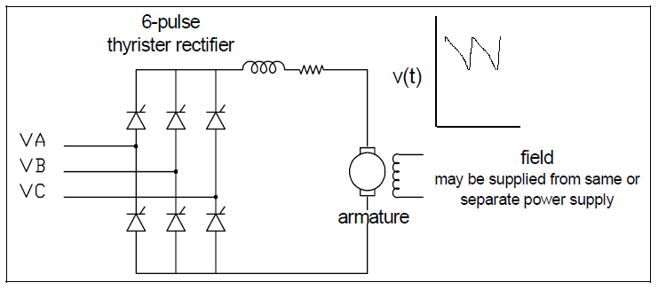
Rectification is the only step required for dc drives. Therefore, they have the advantage of relatively simple control electronics. The dc drive can offer a wider speed range and higher starting torque than an ac system. However, purchase and maintenance costs for dc motors are high, while the cost of power electronic devices has dropped year after year. Economic considerations limit the dc drive to applications that require the speed and torque characteristics of the dc motor.
Most dc drives use the 6-pulse rectifier shown in Figure 4. Large drives may employ a 12-pulse rectifier. This reduces thyristor current duties and eliminates ac current harmonics at certain frequencies.
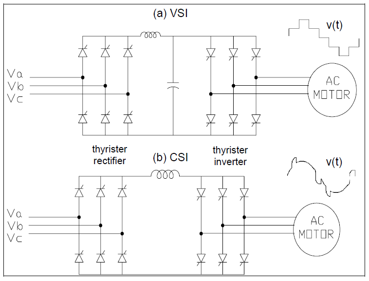
In ac drives, the rectifier output is inverted to produce ac voltage for the motor. Inverters are classified as VSI or CSI. The VSI (voltage source inverter) requires a constant dc (i.e., low ripple) voltage input, requiring the use of a capacitor or LC filter in the dc link. The CSI (current source inverter) requires a constant current input; hence a series inductor is placed in the dc link.
AC drives generally use standard squirrel cage induction motors. These motors are rugged, relatively low in cost, and require little maintenance. Synchronous motors are used where precise speed control is critical. The majority of applications fall into the following three categories.
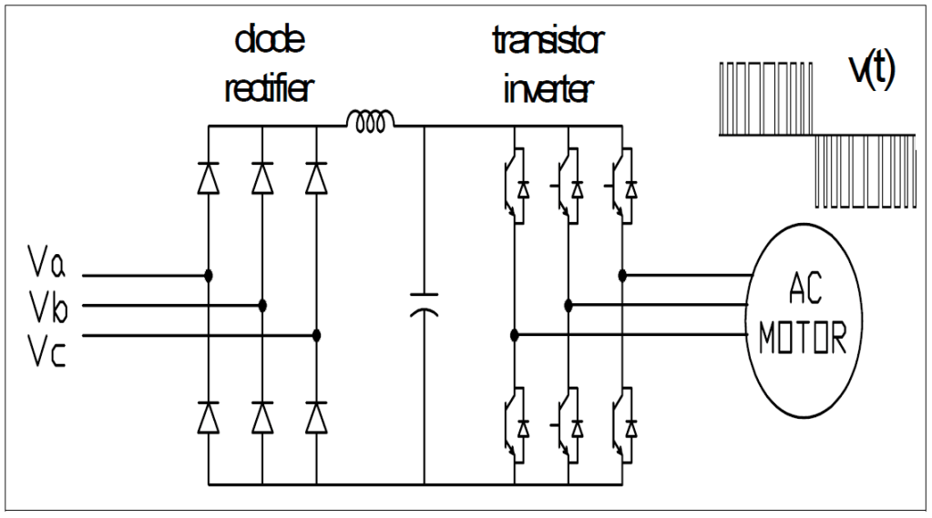
The most popular configuration uses a voltage source inverter employing pulse width modulation (PWM) techniques to synthesize an ac waveform as a train of variable width dc pulses. The inverter uses SCRs, GTO (gate turn off) thyristors, or power transistors for this purpose. The VSI PWM drive usually offers the best energy efficiency over wide-speed range applications for drives up through at least 500 HP. Another advantage of PWM drives is that, unlike other types of drives, it is not necessary to vary rectifier output voltage to control motor speed. This allows the rectifier thyristors to be replaced with diodes, and the thyristor control circuitry to be eliminated.
Very high power drives employ SCR rectifiers and inverters. These may be 6-pulse drives or 12-pulse configurations may be employed. VSI drives are limited to applications that do not require rapid changes in speed. CSI drives have good acceleration/deceleration characteristics, but require a motor with leading power factor (synchronous or induction with capacitors) or added control circuitry to commutate (turn off) the inverter thyristors. In either case, the CSI drive must be designed for use with a specific motor. Thyristors in current source inverters must be protected against inductive voltage spikes, which increases the cost of this type of drive.
Harmonic characteristics
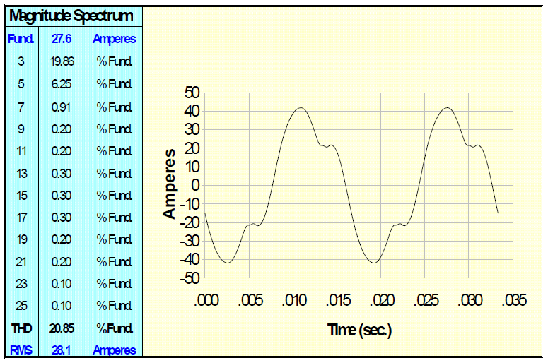
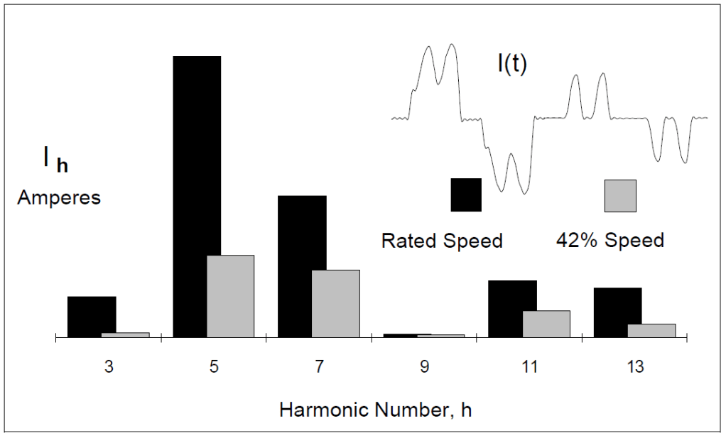
6-pulse drives inject currents into the ac system at harmonic numbers 5, 7, 11, 13, 17, 19, and so on. Although distortion of the current waveform increases at low drive speeds, the harmonic current injected into the system is greatest when the drive is operating at rated speed. This is the limiting operating condition.
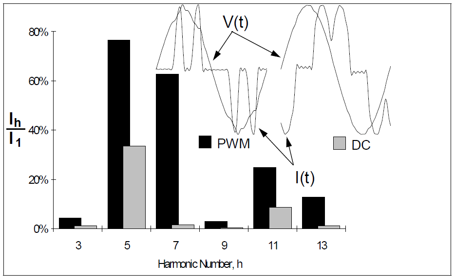
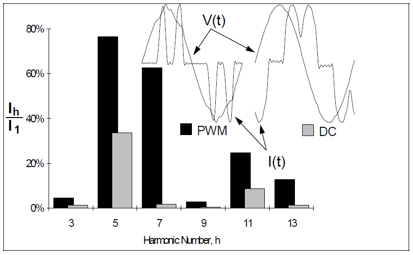
From the perspective of the ac system, the VSI PWM drive appears as a capacitance behind a diode bridge, while dc and CSI drives each appear as an inductance behind a thyristor bridge. Comparing the ac current waveforms for each type (Figure 8) shows that VSI PWM harmonic current magnitudes are more severe, but the displacement power is close to unity. Power factor correction is not necessary for this type of drive. Without power factor correction capacitors, the potential for harmonic problems is greatly reduced. DC and CSI drives, on the other hand, exhibit poor displacement power factor at low speeds.
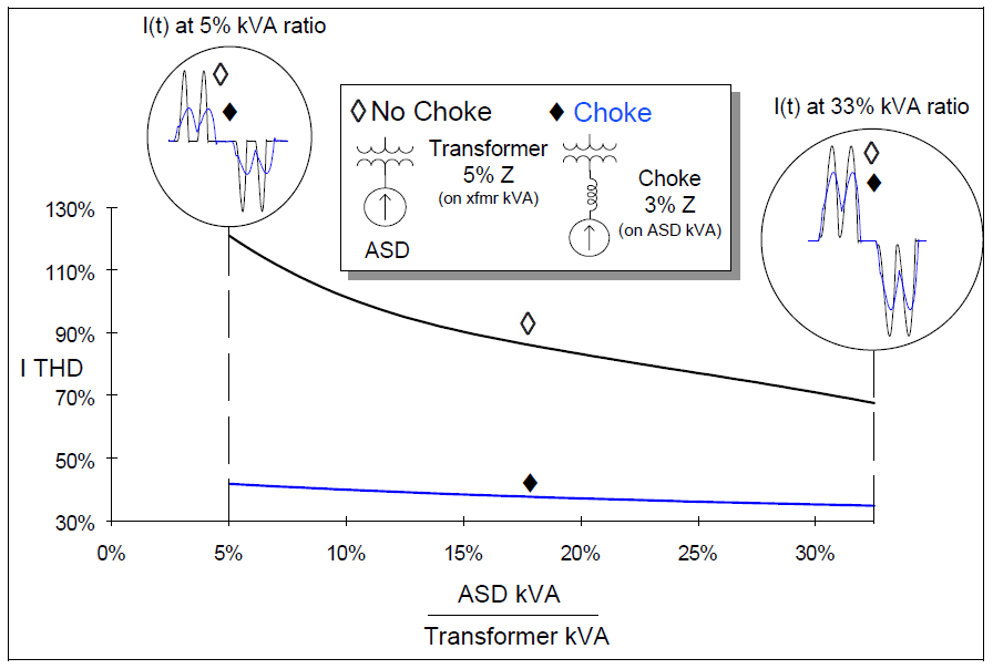
AC line chokes
Inserting reactance between an adjustable speed drive and the system reduces the harmonic content of the ac line current. Figure 9 shows that substantial improvement is possible when the capacity of the adjustable speed drive is small relative to the transformer supplying it. As the adjustable speed drive kVA / transformer kVA ratio is increased, the transformer reactance becomes increasingly effective in reducing harmonic current magnitudes, while the incremental improvement obtained by adding line chokes becomes smaller.
Harmonic Cancellation
A magnitude and a phase angle characterize each of the sinusoids that comprise the Fourier series of a distorted waveform. If there is only one harmonic load in the system, phase angles are not important – THD, IEEE Std. 519, capacitor duty and other calculations only require harmonic magnitudes.
But when the system contains multiple nonlinear loads, phase angles must be considered when calculating how harmonic currents from these loads combine. If two loads inject currents at a particular harmonic that are in phase, the total current at that harmonic can be found by simply adding the magnitudes. Perfect cancellation results when the two currents are 180º out of phase; the total current is the difference of the magnitudes. In the general case, the magnitude of the total current is somewhere between these two extremes.
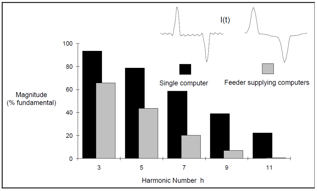
Assuming that harmonic currents are in phase in order to estimate total current can lead to overstated harmonic levels. It is not appropriate to assume that a feeder supplying N identical loads has harmonic currents that are N times as large as the corresponding currents for a single load. The example of Figure 10 shows that this assumption would lead to errors which grow worse as harmonic number increases. Differences in current phase angles between individual loads arise due to the impedance of the feeder. Because the impedance increases with frequency, the shift in phase angles between loads increases with frequency, and cancellation becomes more pronounced.
HARMONICS AND POWER FACTOR
Power factor is a measure of the power utilization efficiency of a load.
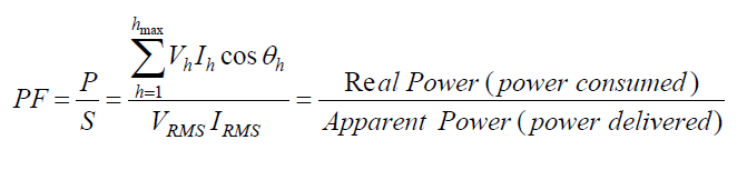
where θh is the angle between the voltage and current sinusoids at harmonic h, and Vh & Ih are the RMS values of these sinusoids. If the system contains no harmonics, this expression simplifies to:
PF = cos θ1
Although this is not a valid measure of utilization efficiency in harmonic systems, it is the “power factor” that the utility uses as the basis for assessing penalties. Two power factors are defined:
TPF ≡ P/S (True Power Factor)
DPF ≡ cos θ1 (Displacement Power Factor)
The PWM and dc adjustable speed drive current and voltage waveforms of Figure 11 illustrate the difference between TPF and DPF. Because of the high current distortion, both drives have poor true power factors. The displacement angle between the fundamental voltage and current components is large for the dc drive, but not for the PWM drive. The dc drive would be penalized by the utility for poor power factor, but the ac drive may not be penalized.
EVALUATION OF SYSTEM IMPEDANCE
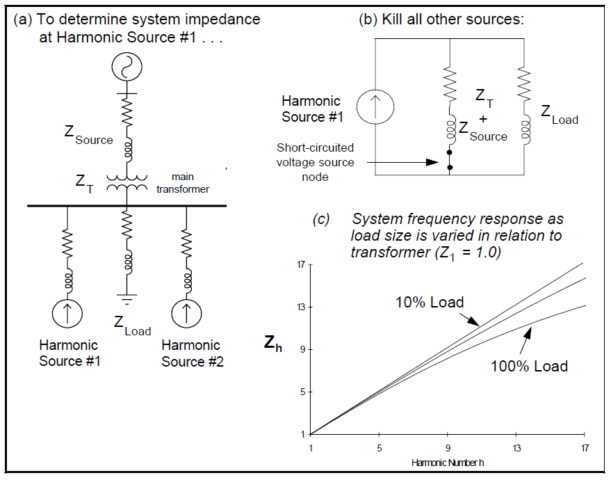
The voltage distortion that results from harmonic current injection is a function of the power system’s impedance. As illustrated in Figure 12, the response to a particular harmonic source is found by removing all other current sources and grounding all voltage source buses. Part (c) of the Figure, shows little difference between high-load and low-load harmonic impedance. This is because the load impedance is about 20 times higher than the source impedance, even at full load. The source impedance dominates the system response.
Effect of capacitor banks on system impedance
To visualize the response of the system when a capacitor is present, it is helpful to assume that the source impedance is purely inductive. This has been done for the circuit of Figure 13(a). The simplified circuit shown in part (b) of the figure illustrates that, from the perspective of a harmonic source, the capacitor appears to be in parallel with the reactance of the transformer and utility source. Parallel resonance occurs at the frequency where the impedance of this parallel combination approaches infinity. The harmonic number at parallel resonance is:
hp = √( XC / XSC ) = √( MVASC / MVARCAP )
where XSC is the short-circuit reactance at the transformer secondary, XT + XS.
If resonance occurs at or near a frequency excited by the harmonic source, high voltage distortion and large circulating currents may result. At most industrial and commercial systems, the dominant variable controlling the parallel resonant frequency is the size of the capacitor bank in relation to the facility’s main transformer. The effect of varying capacitor size is shown in Figure 13(c).
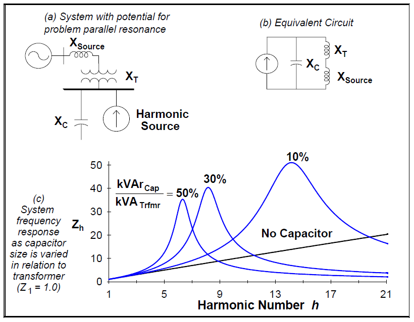
Figure 13(c) shows that adding significant power factor correction will likely result in a parallel resonance near a frequency excited by a harmonic source. The damping provided by resistive loads in the system is usually sufficient to prevent catastrophic voltages and currents. Figure 14 shows that as little as 10% resistive loading can have a significant impact on peak impedance. Motor loads, on the other hand, are primarily inductive at harmonic frequencies. Motors provide little damping and may increase distortion by shifting the resonance closer to a problem harmonic.

A capacitor may also introduce a series resonance. This occurs when, from the perspective of a harmonic source, an inductance and a capacitance appear to be in series. An example of this occurs when a capacitor is applied at an industrial facility’s 480 volt bus. The capacitive reactance XC and the transformer inductive reactance XL appear to be in series to a harmonic source on the utility distribution system. The reactance of the series branch approaches zero at harmonic number:
hs = √ XC / XL
Unlike parallel resonance, high peak voltages are not a problem with series resonance. Series resonances are less destructive, but a series resonance increases a capacitor’s current duty, and may cause nuisance capacitor fuse operations, or even capacitor failure.
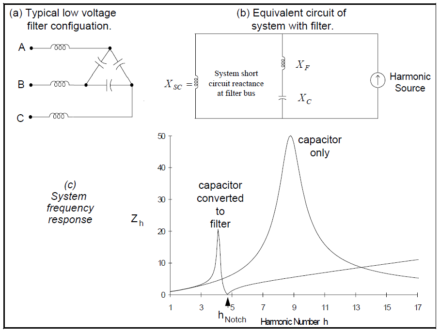
Effect of harmonic filters on system impedance
The most common type filter is the single-tuned (“notch”) filter illustrated in Figure 15. The notch filter is an intentional series resonance; the filter impedance is designed to drop off sharply at a frequency close to the harmonic to be suppressed. Thus, harmonic currents are diverted from their normal flow path into the filter.
Notch filters can be designed to provide power factor correction in addition to harmonic suppression. Figure 15(c) shows the effect of converting an existing capacitor bank to a filter. From the series resonance equation, the harmonic number of the notch frequency is:
hNotch = √ XC / XF = kVCapRated / √( MVACapRated * XF )
Converting a capacitor bank to a harmonic filter forces the parallel resonant frequency to a value below the notch frequency. When the filter is tuned to the lowest harmonic excited by nonlinear loads on the system, the parallel resonance problem is eliminated. If the filter is tuned to a harmonic above a harmonic excited by a nonlinear load, the filter may shift the resonant frequency to this harmonic. Filters are added to the system starting with the lowest problem harmonic. For example, installing a seventh harmonic filter usually requires that a fifth harmonic filter also be installed.
Because the capacitor is connected in delta, the filter configuration of Figure 15(a) does not admit zero-sequence currents. This makes it largely ineffective for filtering triplen harmonics. Other solutions must be employed when it becomes necessary to control third harmonic currents, because 480 volt capacitors are invariably configured in delta.
Filter design is an iterative process. The final filter design specifications must meet the requirements of ANSI/IEEE Std. 18: IEEE Standard for Shunt Power Capacitors:
1. RMS voltage should be less than 110% of the rated voltage.
2. The peak voltage should be less than 120% of the rated peak voltage.
3. The reactive power delivered by the capacitor should be less than 135% of the rated kVAR.
The capacitor RMS current should be less than 180% of rated current. However, this limit must be lowered to 130 – 165% to prevent nuisance capacitor fuse operations.
SUMMARY
The fundamentals associated with power system harmonics have been presented. The source of the harmonic problems has been identified and potential solutions have been discussed.
REFERENCES
“Electrical Power System Quality”, Roger C. Dugan, Mark F. McGranaghan, H. Wayne Beaty
RELATED STANDARDS
IEEE Std. 519
ANSI/IEEE Std. 18-1980
