Published by Electrotek Concepts, Inc., PQSoft Case Study: Harmonic Evaluation at an Industrial Facility, Document ID: PQS0502, Date: March 31, 2005.
Abstract: A harmonic evaluation was performed at the plastic film manufacturer’s facility. The goals of the evaluation were to develop a solution to mitigate the harmonic voltage distortion caused by the ac and dc adjustable speed drives; the solution must allow the utility to install power factor correction equipment on the 13.8 kV distribution system that supplies the facility. The customer is also interested in improving power factor at the manufacturing facility.
INTRODUCTION
Plastic Film Maker is a manufacturer of polypropylene film that is extruded into plastic sheets for use in many different industries. Local Utility supplies power to the Plastic Film Maker facility through six 13.8kV/480/277V padmount service transformers. The transformers are either 2,500 kVA or 3,000 kVA and are connected delta/wye. The six facility transformers are supplied from a 69/13.8kV substation transformer that is about 1,000 feet from the plant.
The Plastic Film Maker process load is made up of resistive heating, adjustable speed drives, and miscellaneous facility load. The process utilizes both ac and dc adjustable speed drives.
Passive harmonic filters are installed at the 480 volt buses of each of the six facility transformers. Five of the filters are rated at 300 kVAR and one is a 600 kVAR bank. All of the filters are tuned to about 249 Hz (4.1 to 4.2 harmonic).
The harmonic evaluation includes measurements at Plastic Film Maker, modeling of the Plastic Film Maker power system, and harmonic simulations.
The harmonic evaluation meets the following objectives:
1. Perform a site survey and power quality audit of the Plastic Film Maker facility.
2. Evaluate the effect of power quality on reliable operation of equipment.
3. Evaluate transformer overheating, derating and impact of harmonic distortion on transformer life.
4. Evaluate harmonic distortion with respect to IEEE Std. 519-1992.
5. Provide recommendations on how to add 10 MW of process load to the Plastic Film Maker facility.

Field Measurements
Field measurements were taken at each main bus.

Simulations
A power system model for the Plastic Film Maker facility and the supplying Local Utility power system was developed. The model was used to simulate harmonic voltage distortion and to evaluate power system impedance with respect to power system configurations and equipment.
Harmonic Simulations
The harmonic simulations performed with SuperHarm were verified with the measurements that were taken at the Plastic Film Maker facility. Measurements are used to create the base case for the harmonic simulations. The measurements that represent the worst case harmonic current injected into the power system are used to develop the base case model. The base case represents “normal” conditions at Plastic Film Maker.
The base case simulations are compared with the measurements to verify the accuracy of the model. Table 1 – Simulation Base Case Comparison to Measurements shows the comparison between the measurement THDV and the simulated THDV at the 480 volt main buses.
Table 1 – Simulation Base Case Comparison to Measurements
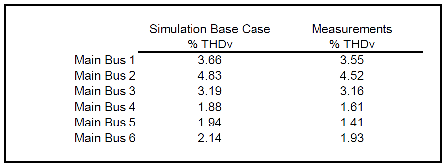
Measurements were not performed at the 13.8 kV bus on November 16th or 17th. Simulations show the harmonic voltage and current distortion that can be expected at the PCC for different conditions. The base case THDV at the PCC is 1.50% and the base case TDD is 9.75%. The demand current used to calculate the TDD is 250 amps.
IEEE Std. 519-1992 Evaluation
The point of common coupling (PCC) is the point on the electrical power system that is common between the utility, the customer performing the evaluation, and all other customers served from the same supply. At Plastic Film Maker’s Morristown facility, the PCC is the 13.8 kV Local Utility supply to the 6 facility substation transformers. The 13.8 kV supply to Plastic Film Maker is the point that is common to Local Utility, Plastic Film Maker, and other customers served from the 13.8 kV supply.
The total demand distortion (TDD) is the ratio of the harmonic current injected into the utility power system by a facility to the maximum average monthly demand current. TDD is a better indicator of harmonic current than THDI. THDI is a measure of how distorted the current is and it does not provide any indication of whether or not the current distortion should be a concern or not. TDD has an inherent quality that THDI does not have because it evaluates harmonic current relative to demand current.
The IEEE Std. 519 recommended TDD limit at Plastic Film Maker’s 13.8 kV bus is 8.0%. The maximum simulated TDD at the PCC with Option 1 exercised is 4.24%.
The recommended THDV limit at Plastic Film Maker’s 13.8 kV bus is 5.0%. The maximum simulated THDV at the PCC with the recommended harmonic filters on-line is 1.60%.
Frequency Scans
Figure 3 shows the results of the base case frequency scan. The series resonance is at the 4.2 harmonic. The series resonance results from the installed filters at the 480 volt main buses. The frequency scan for the recommended option will look the same except the series resonance (notch) will be at the 4.7th harmonic.

There are filters installed at Plastic Film Maker. The filters are installed at the 480 volt main buses and are tuned to about the 4.2 harmonic. The reactors installed in series with the capacitor banks appear to be an after thought because the capacitors are rated at 480 volts. Capacitor banks configured as filters at the 480 volt level should use capacitors that are rated greater than 480 volts due to the voltage rise at the capacitors. 600 volt capacitors work well in these applications since the voltage does not exceed the rating of the capacitors.
Power Factor Correction
This section summarizes the power factor improvement that results from the installation of passive filters at Plastic Film Maker.
Summary of Reactive Power Requirements
Table 2 summarizes the power factor improvement that results from adding compensation at the main 480 volt buses 4, 5, and 6. A compensation of about 320 kVAR results from adding 500 kVAR of 600 volt capacitors for this application on the 480 volt system.
Table 2 – Results of adding Compensation to Buses 4, 5, and 6
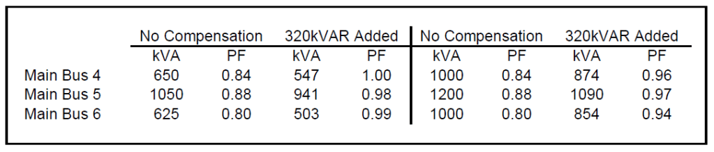
Table 3 summarizes the power factor improvement that results from adding compensation at the main 480 volt buses 1, 2, and 3. A compensation of about 960 kVAR results from adding 1,500 kVAR of 600 volt capacitors for this application on the 480 volt system.
Table 3 – Results of adding Compensation to Buses 1, 2, and 3

The power factor correction should be configured as a harmonic filter tuned to the 4.7th harmonic (282 Hz) to prevent excessive distortion and problems with magnification of capacitor switching transients at the 480 volt level.
Recommendations
Install Harmonic Filters at All Main Buses Tuned to 4.7h
The existing filters that are tuned near the 4.1 harmonic should be removed before the installation of passive harmonic filter banks tuned to 282 Hz (4.7 harmonic). The results of the study indicate the installation of 1,500 kVAR filters at main buses 1, 2, and 3 and the installation of 500 kVAR filters at main buses 4, 5, and 6. Appendix A includes the filter design spreadsheets for both the 1,500 kVAR and the 500 kVAR filter.
Recommended filter sizes and buses:
1. 1,500 kVAR at Main Bus 1
2. 1,500 kVAR at Main Bus 2
3. 1,500 kVAR at Main Bus 3
4. 500 kVAR expandable to 1,000 kVAR, or more, at Main Bus 4
5. 500 kVAR expandable to 1,000 kVAR, or more, at Main Bus 5
6. 500 kVAR expandable to 1,000 kVAR, or more, at Main Bus 6
The new filters could be installed as fixed banks. The voltage rise associated with the 1,500 kVAR filters is 3.3%. The calculated voltage rise at the 480 volt buses with no load, or a small amount of load, is 16 volts. Controls should be implemented to remove the filters from service during light load conditions. The new filters at buses 4, 5, and 6 can be installed to allow for the installation of additional compensation in the future.
Billing data shows that the power factor of the facility is lowest during the summer months. The power factor may be low during the summer because of air conditioner operation. The billing data shows that 1,000 kVAR banks may be required to prevent the power factor from decreasing during the summer. Calculations show that the reactive demand charge during the summer will be about $1,200 with 500 kVAR banks at buses 4, 5, and 6. The reactive demand charge would be reduced to $498 if at least 1,000 kVAR filters were installed at these buses.
1,000 kVAR filters at buses 4, 5, and 6 would help improve the overall power factor of the facility. A leading power factor at these buses is not a problem as long as the voltage does not exceed an unacceptably high level.
Calculations show that plant power factor will range from about 0.87 to 0.95 with the following conditions:
− Existing filters removed from all buses.
− New 1,500 kVAR tuned banks installed at buses 1, 2, and 3.
− New 500 kVAR tuned banks installed at buses 4, 5, and 6.
Calculations show that plant power factor will range from about 0.91 to 0.95 with the following conditions:
− Existing filters removed from all buses.
− New 1,500 kVAR tuned banks installed at buses 1, 2, and 3.
− New 1,000 kVAR tuned banks installed at buses 4, 5, and 6.
Additional compensation must be installed for Plastic Film Maker’s plant power factor to be maintained greater than 0.95 when process load is increased. The recommended filters will reduce the average monthly reactive demand charge from $1,808 to $498.
This option requires the purchase of at least 6,000 kVAR of compensation as harmonic filters. This option does not allow Plastic Film Maker to continue to utilize any of the existing filters. Filters tuned to the 4.7 harmonic perform a better job of reducing the harmonic current injected into the utility power system than filters tuned to the 4.2 harmonic. The new filters will be more robust and more reliable than the existing filters.
Harmonic cancellation
The results of the study do not indicate a need for the installation of 13.8kV/480V delta/delta transformers at Plastic Film Maker. Applying a mix of delta/wye and delta/delta transformers had been considered because this practice can provide additional cancellation of harmonic current, especially the 5th and 7th harmonics that are usually dominant in industrial facilities.
Simulations show that some harmonic cancellation exists at the 480 volt level and the 13.8 kV level. The significant amount of dc drives at Plastic Film Maker makes the application of delta/delta transformers less attractive than if ac drives were a larger part of the total load. The operating conditions of dc drives can vary greatly. If the drive is running near it’s rating the displacement power factor is high. When the drive operates at relatively low power levels, the displacement power factor will be low. The variation in load levels and dc drive displacement power factor enhances the cancellation of harmonics.
Facility electrical personnel need to be aware of the 30 degree phase differential when delta/delta and delta/wye transformers do supply a facility. The 480 volt system would not be able to be completely paralleled without the use of additional phase shifting transformers. Paralleling the secondary, or low voltage, windings of the facility transformers may or may not be a concern at Plastic Film Maker.
The results of the study do not indicate that the application of delta/delta transformers at Plastic Film Maker would improve the cancellation of harmonic current at the PCC significantly.
Transformer derating
The 13.8kV/480V facility transformers at Plastic Film Maker do not need to be derated after the recommended filters are installed and they are in operation. Calculations show that transformers without new filters installed should be derated to 0.92 p.u. This amount of derating is typical. Transformer derating is more of a concern when a transformer is supplying one adjustable speed drive. When a transformer is dedicated to serving only one drive there is no harmonic cancellation and transformer derating factors can range from 0.90 to 0.80 p.u.
Addition of process load at Plastic Film Maker
The results of the study do indicate that the Plastic Film Maker use the recommendations of this harmonic evaluation when new facility transformers and process load is added. The recommended filters that will be installed at buses 1, 2, and 3 allow Plastic Film Maker to add process load to those buses up to the rating of the transformers.
A harmonic filter should be installed at the transformer secondary, the 480 volt bus, when additional facility transformers are added to supply new process load. If the load supplied by the new transformer is comparable to the load supplied by facility transformers 1, 2, or 3, then a 1,500 kVAR filter should be applied. If the load supplied by the transformer is comparable to the load supplied by facility transformers 4, 5, or 6, then a 500 kVAR filter should be applied. A check should be performed to verify the proper filter size before additional process lines are in operation at Plastic Film Maker.
Plastic Film Maker can add load to all of the existing facility transformers. The 1,500 kVAR filters are based on 3,000 kVA of load with harmonic load current of 900 amps (25% of the fundamental current for 3,000 kVA). The 500 kVAR filters are based on 1,500 kVA of load with harmonic load current of 270 amps (15% of the fundamental current for 1,500 kVA).
