Published by Terry Chandler, Director of Engineering, Power Quality Thailand Ltd. & Power Quality Inc., USA. Application Note, Sept. 2013
Emails: terryc@powerquality.org, terryc@powerquality.co.th
Typical PTs and CTs cause errors and issues in PQ measurements in three areas:
1. Harmonics As the PT and CT have very poor frequency response, they are in affect are a low pass filter on the secondary voltage of the PT or CT. Note: A frequency response curve below shows the output above 25th harmonic (1.25 kHz/or 0.8 ms) is amplified by more than 10% and at the 40th harmonic ( 2.0 kHz/0.5 ms) the output is amplified more than 50% and at 47th harmonic the transient would be amplified by 4.5 X the actual. At the 50th (2500 Hz/0.4ms) harmonic and higher the transient would be attenuated by more than 50%!
2. Transients: Depending on the actual PT/CT high speed transients will be magnified at some frequencies and attenuated at higher frequencies. In the example below at transient of less than 4 milliseconds would be attenuated by 50%. Faster than 4 ms would be attenuated even more.
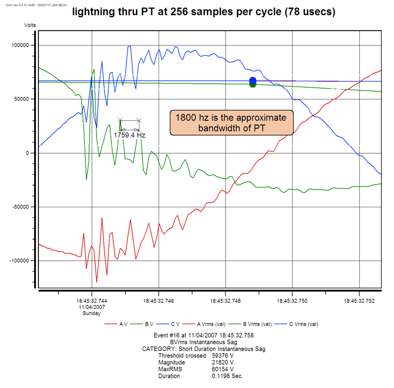
3. Converting fast transients to ringing impulses. See the diagram below for examples of actually lightning strikes converted to 1.250 kHz ringing transients.

Background on Filter characteristics.
High-pass filter. Attenuates the low frequencies below the lower limit of the low pass filter. See diagram. (passes the high frequencies with little or no attenuation) These are used to remove the 50/60 Hz from a signal so the fundamental voltage does not interfere with high frequency transient measurements.
Low-pass filter. Attenuates the high frequencies above the high limit of the filter. (see diagram) It passes the lower frequencies with little or no attenuation. These are used when high frequency signals could interfere with the measurement of the fundamental or the low order harmonics. (less than 125th for example)

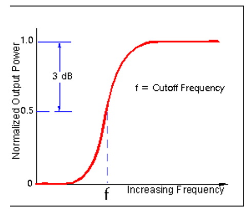
Band-pass filters. Are the combination of the low pass and high pass filters. That is they pass frequencies within the band but attenuate the frequencies above the pass band and below the pass band. Bandwidth describes the frequencies that pass a filter with less than 3dB attenuation. (see below)

References: Network Performance, Reliability and Quality of Service Committee (PRQC) PRQC develops and recommends standards, requirements, and technical reports related to the performance, reliability, and associated security aspects of communications networks, as well as the processing of voice, audio, data, image, and video signals, and their multimedia integration. PRQC also develops and recommends positions on, and fosters consistency with, standards and related subjects under consideration in other North American and international standards bodies.
http://www.mathworks.com/help/rf/examples/bandpass-filter-response.html
IEEE definitions of electronic words dictionary
IEC standard definitions
http://www.trenchgroup.com/en/Products-Solutions/Instrument-Transformers/Technical-Papers
Addendum A
PT and CT transducer limitations for Power Quality recording measurements considerations for transient capture at high and medium voltages
Installed protection or metering PTs (potential transformers ) and CTs (current transformers) are designed for use at the fundamental frequency (50Hz/60Hz) regardless of the technology employed. That both transformer (inductive) technology or Capacitive divider technology.
Specialty measurement PT’s are resistive dividers and are suitable for PQ measurements.
Figure below shows the typical circuit designs.
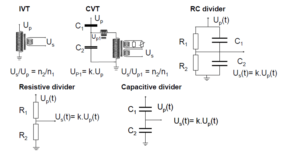
IVT (Inductive voltage transformers are designed for nominal frequency). Resonances between the layer inductance and stray capacitance can result in large amplitude and phase errors. The higher the voltage level the lower the first resonance.
Accuracy curves below show the situation in more detail. Note: accuracy is normal up the 25th harmonic (1250 hz). By the 50th harmonic (2500 Hz) the accuracy varies from -75% to +450 %!!
This means any transient measurement about 1250 Hz (800 microseconds) will have unknown accuracy. And any transient measured at or above 2500 Hz (400 microseconds) will have errors ranging from -75% to + 450 %.
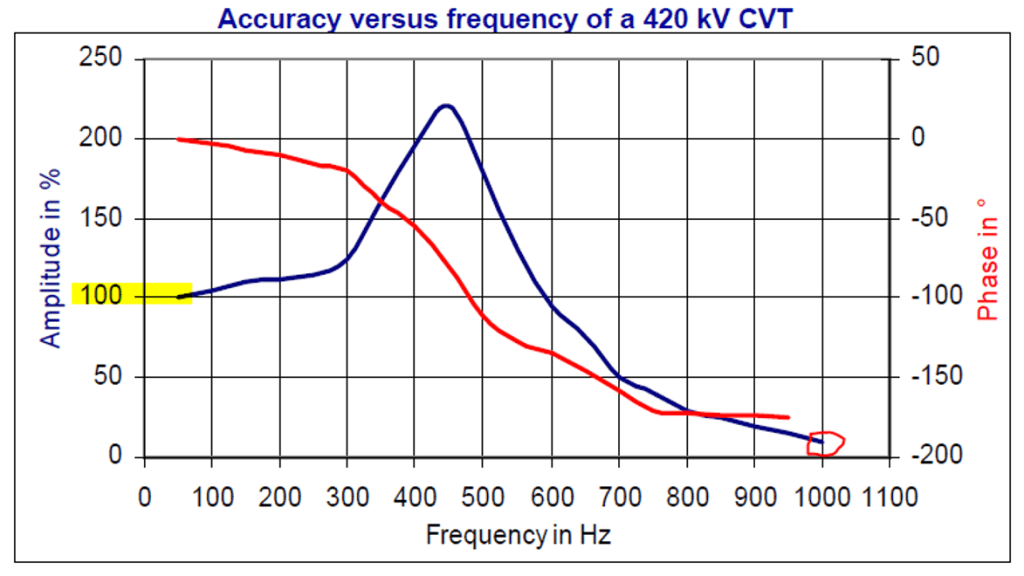
Capacitive coupled PTs are much worse. This data is from a 420KV CVT but the accuracy specifications are about the same for the entire high voltage range due to the tuned circuit. Accuracy error is >200% 450 Hz and -75% (and getting worse) at 1000 Hz (1MS)
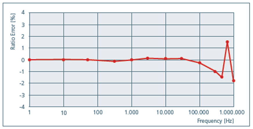
So simply stated, purchasing an option in a PQ instrument that measures high speed transients is not advised and worse any transient recorded will not be valid data and user has no easy to determine what is valid data. The exception would be for special tests where a RC divider type PT is supplied. Note in the diagram below the flat frequency response from 1 Hz to nearly 100,000 KHZ. (10 microseconds)
Below is an example of a PQ instrument recording (at 256 samples per cycle) a lightning strike (and resultant voltage sag) on a 115kV line in Vietnam. Note: The frequency of the ringing transient.
The very important capability of the instrument is to capture all 3 phases of voltage and current simultaneously at the sample frequency so the user can see the details of the transient without having to analyze the capability of the instrument which captured the transient.


Such an important technology writeup.
Harmonics measurement getting affected by CTs and PTs frequency response characteristics.
Highly useful in Designing of:
1. Active Harmonic filter : for arriving at right level of mitigation. Stability of the close loop individual harmonic is dependent on such feature being added to AHF harmonic measurement.
2. Energy meter where KVAH billing (like in India) is getting affected by harmonics.
3. PQ analyzer and its CT / PT sensing devices.
LikeLike