Published by Mikhail ANDREEV, Aleksey SUVOROV, Alisher ASKAROV, Anton KIEVETS, Vladimir RUDNIK, Tomsk Polytechnic University, Russia
Abstract. The current trend in the development of electric power systems is the integration of renewable energy sources in the form of distributed generation. It was revealed that one of the main reasons inhibiting this process is a change in the EPS operating modes, which in turn has a significant impact on the operation of relay protection and automation and, as a consequence, on their setting. A decrease in sensitivity and a violation of relay protection selectivity in distribution network in the case of integration of wind power generation into EPS have been experimentally proved. An important factor is the capacity and location of the wind power generation facilities connection. In addition, the article analyzes the existing approaches to implement the relay protection of such power systems. As a result, it is theoretically proved the need to develop new methods and means for comprehensive setting up of relay protection and automation, since existing approaches either limit the integration of new installations, or they are difficult to implement, or not flexible enough.
Streszczenie. W rozproszonych sieciach w skład których wchodzą odnawialne źródła energii pojawia się problem zmiany warunków pracy przekaźnikowych systemów zabeW artykuler analizowano wpływ odnawialnych źródeł energii na systemy zabezpieczeń. zpieczeń. Wykazano że istnieje potrzeba opracowania nowych metod zabezpieczeń ponieważ istniejące mają ograniczone możliwości zastosowań. (Wpływ odnawialnych źródeł energii na systemy zabezpieczeń)
Keyword: power system simulation, relay protection, mathematical modeling, distributed generation, renewable energy sources, HRTSim.
Słowa kluczowe: przekażnik, systemy zabezpieczeń, odnawialne źródła energii
1. Introduction
According to the statistics [1] over the past 15 years, the increase in electricity consumption amounted to approximately 35-40%. This trend leads to the need for new energy supply capacity, which are mainly based on the use of fossil resources. Moreover, in the developed countries, one of the priority directions for the development of electric power systems (EPS) is the transition to renewable energy sources (RES). The total power generated by RES using wind and solar energy has increased by more than 30% over the past 15 years. According to the European Union plans, the share of RES by 2020 should be 20%, and by 2050 – 80-95% [2]. However, the actual figures are much more modest and hardly half of the planned volume.
One of the main reasons inhibiting the integration of RES is the change in the EPS operation modes, which in turn has a significant impact on the operation of relay protection (RP) and automation.
The challenge of adequate EPS control and protection remains relevant, due to the complexity of its solution. The latter, in turn, is due to the fact that any EPS is a complex, nonlinear, multi-parameter and dynamic system. The authors are implementing a project aimed at studying the processes in EPS, as well as the development of methods and means for determining the settings of RP, which ensure their reliable and efficient operation in specific operating conditions. At the same time, it is impossible not to take into account the previously noted trend in the development of EPS. In this regard, the aim of the first stage of the project, devoted to the study of modern EPS, containing in particular RES, was a theoretical and experimental study of the processes in such power systems, as well as a preliminary assessment of their impact on the operation of RP devices. The results of this work are reflected further in the article.
2. Materials and methods
2.1. Theoretical part
Distribution networks with one source of supply, as a rule, are protected by overcurrent protection. In the case of a more complex network configuration, directional overcurrent protection is used. As it is known, such protections are not installed in loop networks with several power sources. Although, in the case of using RES as distributed generation, the radial network transforms into network with loop architecture, consequently, directional overcurrent protection with fixed time dial setting and plug multiplier setting cannot be used. The value of the short-circuit current and its direction depends on the type, capacity and location of RES in the network [3, 4]. The main issues of ensuring the correct RP operation during the RES integration are discussed below:
(1) Protection Insensitivity. The integration of RES, depending on the type, capacity and installation location, can significantly affect on the short-circuit current. For synchronous types of RES (small hydro power plants), the short-circuit current can exceed the calculated rated current by 5-6 times. Inverter-based RES (such as photovoltaic power station) generate a small short-circuit current in the range from 1.1 to 2 times the rated current. This may not be enough for overcurrent protection tripping for circuits, as shown in Figure 1a.
(2) Violation of Selectivity. The large-scale integration of RES into distribution networks leads to the fact that they create a bi-directional short-circuit current on most feeders. Non-directional overcurrent protection cannot provide selective protection for such networks. As shown in Figure 1b, in case of a short-circuit, relay R2 may trip earlier than relay R1. In large interconnected distribution networks, some relays may trip before the previous relay has tripped, resulting in the disconnection of most elements of the network.
(3) Autoreclosing Issues. As shown in Figure 2, when the fault is partially cleared on one side where autoreclosing devices are installed, it is still supplied by RES. The short-circuit current generated by RES can cause an electric arc through the autoreclosing circuit breaker.
2.2 Practical part
The formulated above features of EPS with RES are confirmed by the following studies for the IEEE 14-bus modified test system (Figure 3). The studies, described in the article, were carried out via the hardware-software power system simulator – Hybrid Real-Time Power System Simulator (HRTSim) [5, 6]. A specialized hybrid processor compatible with the HRTSim was developed for adequate and comprehensive simulation of a wind power plant (WPP). The following is a brief summary of the specialized hybrid processor structure, the combination of which forms a WPP of any rated capacity.
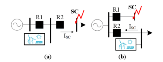
Fig. 1. (a) Impact of RES on the protection sensitivity; (b) Impact of RES on the protection selectivity
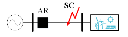
Fig. 2. Autoreclosing issues in case of RES connection to the network, where AR is an autorecloser
The wind turbine power generation system is an electromechanical complex for converting the mechanical energy of rotation of a rotor hub with low-speed shaft into electrical energy and its further transmission. The main element of a wind turbine is either an electrical machine, or a combination of electrical machine with power electronics devices and electronic control devices – a machine-converter system [7].

Fig. 3. The single-phase view of simulated EPS – IEEE 14-bus modified test system
The type of electrical machine used in wind turbine depends on the capacity of the installation and the nature of the consumers. Electrical machines must satisfy certain requirements, the most important of which are: high reliability in operation under various operating conditions, ease of maintenance, specified service life [7].
There are structurally distinguish wind turbines with horizontal and vertical axes of rotation. At present, wind turbines with a horizontal axis of rotation have become widespread for power generation on an industrial scale due to their advantages; its share in the modern market is about 91% [8, 9].
Wind turbine manufacturers have developed universal models for assessing the electrical and mechanical behavior of generators with a high level of accuracy [10, 11]. However, detailed models from manufacturers are not suitable for modeling and studying the dynamic stability of large-scale power systems due to the large amount of input data, and the high complexity of computational operations, as well as the use of such models for scientific purposes is limited by the confidentiality of such information [12, 13]. In order to solve these issues, the International Electrotechnical Commission (IEC) developed the IEC 61400-27 standard [14] regarding the definition of general (simplified or standard) dynamic models for wind turbines. According to the standard and the provisions of the Institute of Electrical and Electronics Engineers (IEEE) [15, 16], it is accepted to classify wind turbines by the electrical machines type (Figure 4).
Type-1 and Type-2 wind turbines are obsolete installations used since the beginning of the 80s. Due to the low efficiency compared to Type-3 and Type-4 wind turbines, Type-1 and Type-2 turbines are less common on the market and are being actively replaced at the existing WPP [17]. However, their share in the total number of wind turbines is still quite large, and therefore their features must be taken into account in the framework of the study. The main disadvantages of Type-1 and Type-2 wind turbines include:
– use of a gearbox (high mechanical stresses);
– narrow range of rotor rotation speeds;
– transduce of power fluctuations into the EPS;
– large losses on the creation of magnetic fluxes, high magnetization currents;
– power losses in the resistor (Type-2), increasing in proportion to the increase in slip.

Fig. 4. The general topologies of wind turbine models, where GB is a gearbox, IG is an induction generator, SG is a synchronous generator, DFIG is a doubly-fed induction generator, PMSG is a permanent magnet synchronous generator

Fig. 5. Structure of specialized hybrid processor: MPU – microprocessor unit; CPU – central processor unit; PP – peripheral processor; SwP – switching processor; PADC – analog-to-digital conversion processor; ADC – analog-to-digital converters; SSDCS – series and shunt digitally controlled three-phase switches; HCP (EM, T, R, DCC, HPF) – hybrid coprocessors of electrical machine, transformer, reactor, direct current circuit and high-pass filter; LAN – local area network; ED – external device
Over the past decade, the most common among the installed facilities were variable speed wind turbine (Type-3 and Type-4) [18, 19], which allow to achieve optimal output power in a wide range of wind speeds by operating the rotational speed as the input wind speed varies. Variable speed wind turbine control systems allow continuous operating the wind turbine rotational speed so that the wind turbine constantly operates at the highest level of aerodynamic efficiency. In general, such wind turbine are much more stable and have a less detrimental effect on the EPS operating mode compared to Type-1 and Type-2. Thus, the developed specialized hybrid processor implements such types of wind turbine – Type-3 and Type-4 wind turbine, which are currently used in EPS.
Structural scheme of specialized hybrid processor, which takes into account the additional equipment of all types of wind turbines topologies: drive train, gear box, excitation system, control systems and also all kinds of three-phase or single-phase series and shunt commutations of stator and rotor circuits, is presented in Figure 5. In this structural scheme:
1. Microprocessor unit provides all the informational and control functions of specialized hybrid processor: communication with HRTSim server, receiving and processing simulation data, implementation of wind turbine control systems, simulated equipment parameters control, including the state of digitally controlled analog switches of voltage source converter (VSC) and series-shunt digitally controlled three-phase switches (SSDCS). Thus, VSC and SSDCS of specialized hybrid processor are implemented in analog way.
2. Central processor unit is designed to provide interaction via local area network between the HRTSim Server and analog-to-digital conversion processor, peripheral processor and switching processor, and performs the functions of receiving EPS mode data from Server and its transferring to the relevant HCP, transferring of simulation data to Server, synchronization of all microprocessor units of specialized hybrid processor in HRTSim.
3. Analog-to-digital conversion processor provides analog-to-digital conversion, reading and processing of HCP simulation data, and functional control, including dynamic, of the simulated equipment parameters setting in the relevant HCP, in particular parameters of electrical machine, coupling transformer (T), etc., as well as the transfer of the necessary operational data and parameters to peripheral processor. In addition, the analog-to-digital conversion processor performs digitization and functional processing of simulation data for the algorithms implementation of the VSC automatic control system: coordinate transformation, the formation of control actions for pulse-width modulation, etc.
4. Using a peripheral processor, data is received from central processor unit and analog-to-digital conversion processor to simulate the mathematical models of drive train, excitation system and implementation of automatic control systems as well as for the formation and transferring of parameters into HCP electrical machine.
5. Switching processor implements pulse-width modulation and the formation of control actions for digitally controlled analog switches of VSC and SSDCS, as well as protection of VSC and wind turbine in general.
6. Each HCP is a specialized parallel digital-to-analog structure of methodically accurate continuous implicit real-time integration of systems of differential equations of simulated equipment mathematical models with digital control, including functional, of these models
parameters carried out by digital-to-analog conversion, and the conversion of continuous mathematical variables of input-output currents values, represented by instantaneous voltage, into the corresponding physical model currents.
The universality of the specialized hybrid processor structure is achieved due to the following aspects:
1. Using the SSDCS it is possible to configure various topologies of wind turbines:
• when SSDCS1 is on, and SSDCS2, SSDCS3, SSDCS4 is off, Type-1 and Type-2 wind turbines realization is possible;
• when SSDCS1, SSDCS3 and SSDCS4 is on, and SSDCS2 is off, Type-3 wind turbines realization is possible;
• when SSDCS2 and SSDCS4 is on, and SSDCS1 and SSDCS3 is off, Type-4 wind turbines realization is possible.
2. Each HCP can implement various types of simulated equipment (for example, various types of electrical machines, two or three-winding transformer, various high-pass filter structures).
3. The specifics of VSC physical model allows reproducing various topologies of VSC.
4. To ensure the adequacy of switching processes simulation in power semiconductor switches, in particular, to ensure the current-voltage characteristics of each simulated switch, the developed VSC physical model is supplemented by corresponding RC equivalent circuits.
As can be seen from Figure 6, the power characteristics of a wind turbine obtained experimentally via HRTSim coincide with the characteristics obtained using the PSCAD software, which indicates the adequate operation of the implemented aggregate wind turbine mathematical model. In addition, the obtained characteristics provide an opportunity to quantify the operation of a wind turbine model with specific parameters (radius of the blades, rated power of the wind turbine, etc.) at certain wind speeds and pitch angles.

Fig. 6. Wind turbine Power-Speed Characteristic with pitch angle of 0-25° in 5° increments
3. Results and discussion
The following are fragments of the studying results of the WPP impact on the RP operation.
Case 1: the location of WPP installation – Node 14 (110 kV)
Experiment №1 – Line-to-line short-circuit (AB) at Node 13 with a change in capacity of WPP (from 0 to 30 MW) at Node 14. The nature of the short-circuit current change flowing through the transmission line L-17 is of interest (Figure 7) – in this case, short-circuit current decreases with an increase in capacity of WPP. Thus, RP installed at the beginning of L-17 (considering Node 9 as the beginning of a transmission line, and Node 14 as the end), at a certain capacity of WPP will not effectively reserve the RP of the line L-20 (the short-circuit current value will be less than the protection threshold).
Experiment №2 – Three-phase-to-ground short circuit at Node 13 with a change in capacity of WPP (from 0 to 30 MW) at Node 14. In this case, it can be seen an increase in the value of short-circuit current flowing through the L-17 (Figure 8) with an increase in WPP capacity.
Experiment №3 – Location change of a WPP with a rated capacity of 10 MW from Node 9 to Node 13 (a ‘relocatable’ Node 14 with a WPP), the test disturbance is a line-to-line short-circuit (AB). In such experimental study, the short-circuit value is firstly reduced (at x < 0.5 pu, where x is a line impedance), and then is increased (at x > 0.5 pu) as shown in Figure 9. Thus, the RP installed at the beginning of L-17, at a certain WPP location (for example, from 0.28 pu to 0.62 pu) will not effectively reserve the protection of the line L-20 (the short-circuit current value will be less than the protection threshold).
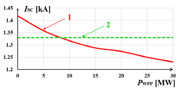
Fig. 7. The value of the short-circuit current flowing through the line L-17 in case of a line-to-line short-circuit (AB) at Node 13: 1 – short-circuit current value; 2 – RP threshold, installed at the beginning of the line L-17
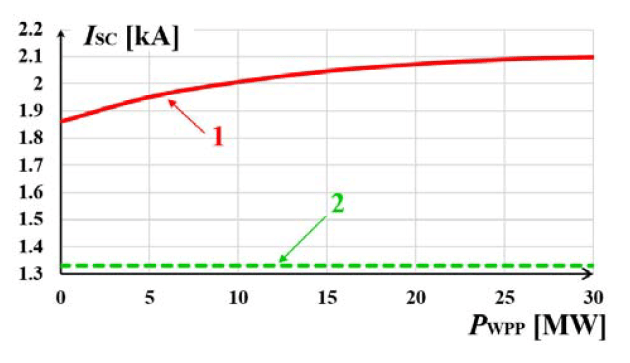
Fig. 8. The value of the short-circuit current flowing through the line L-17 in case of a three-phase-to-ground short-circuit at Node 13: 1 – short-circuit current value; 2 – RP threshold, installed at the beginning of the line L-17
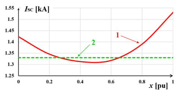
Fig. 9. The value of the short-circuit current flowing through the line L-17 in case of a line-to-line short-circuit at Node 13 and a ‘relocatable’ Node 14 with a WPP: 1 – short-circuit current value; 2 – RP threshold, installed at the beginning of the line L-17
Case 2: WPP with a rated capacity of 30 MW is installed in Node 14, the test disturbance is a three-phase-to-ground short-circuit at Node 10 (Figure 3). The study of two issues:
(i) issue 1 – the change of current flow direction both in the normal operating state and in the emergency state (in case of short circuit);
(ii) issue 2 – the increase in the value of short-circuit current flowing through the transmission line in case of external SCs, consequently, the non-selective tripping of RP is possible (disconnection of non-damaged transmission line, as a result cascade shutdown of other transmission line is possible).
Experiment №1 – without a WPP: as can be seen from Figure 10, in normal state, the current in L-17 flows from Node 9 to the Node 14, in case of short-circuit – the current value decreases, because all currents flow to the fault location.
Experiment №2 – WPP with a rated capacity of 30 MW is installed in Node 14. As can be seen from Figure 11, in normal state, the current in L-17 already flows from Node 14 to Node 9 (the direction of current flow is changed), and in case of short-circuit – there is an increase in the value of current through the line due to the appearance of additional supply of the fault location from the WPP.

Fig. 10. The RMS value of short-circuit current flowing through the line L-17 in normal state and in case of a three-phase-to-ground short-circuit at Node 10 without WPP installation

Fig. 11. The RMS value of short-circuit current flowing through the line L-17 in normal state and in case of a three-phase-to-ground short-circuit at Node 10 with WPP installed in Node 14
As mentioned above, the traditional principles of protection of energy facilities are not suitable for EPS with RES. The existing approaches to the protection of such power systems are discussed further.
1) The protection scheme based on voltage control at the point of connection of RES to the network [20]. The main idea of this protection scheme is to reduce the short-circuit current by RES. During an accident, the control of converter reference current (Iref) is carried out in accordance with (1).

where Imax is the maximum output current that happens at UPCC = 0.88, UPCC is the RMS voltage at the RES connection node, Pdes is the output desired power, k and n are experimentally determined constants.
It is a rather simple method and no additional costs are required for its implementation. However, it may not operate correctly when the voltage drops due to increased load, starting or self-starting of motors, etc. Moreover, the remoteness of the fault location from the point of voltage control reduces the sensitivity of such protection.
2) Distance protection usage [21]. Distance protections are the most common in EPS. Compared with overcurrent protection, distance protections are less affected by changes in network configuration. Distance protections allow to determine the fault location: on the protected object or behind the protection. However, when assessing the sensitivity, the transition resistance is ignored, but in distribution networks its consideration is important is case of RP setting up, because the transmission line are short and most accidents occur through a large transition resistance. With the widespread integration of RES in the form of distributed generation, it is extremely difficult to take into account the transition resistance, so the tripping zone of distance protection characteristics can be either excessive or insufficient, what can cause protection maloperation.
It should be noted other features of the distance protection operation in networks with RES. For example, a change in wind parameters has a significant effect on the tripping zone of distance protection. Fluctuations in wind speed lead to changes in the voltage levels in the network and, accordingly, to changes in the impedance controlled by the protection, and, as a consequence, the instability of the tripping zone of distance protection characteristic. Such uncertainty is unacceptable for the implementation of the protection of the EPS facilities.
Various types of generators are used at WPP, such as induction and synchronous. The dynamics of the transients during short-circuit in case of induction-type generators is different in comparison with traditional synchronous generators, which is an important factor, but is not currently taken into account when forming the distance protection characteristic.
3) As a solution to the problem of the correct RP setting up, ensuring its adequate operation in modern EPS, different algorithms are proposed, for example [22, 23], determining the volume and installation locations of RES in such a way that it does not affect on the settings of RP and accordingly their operation. Such approach eliminates the need for a significant update of existing methods for RP settings calculation, however, it inhibits the integration of RES.
4) In [24], it is proposed to use the directional overcurrent protection with two tripping characteristics: for forward and reverse directions. This approach, however, is aimed only at solving the issue of RP coordination among themselves due to time delays and does not change the concept of overcurrent protection operation. In addition, this method does not solve the issue of the impact of RES on the short-circuit current level.
4. Conclusion
Summarizing the above, it can be confidently state the need to develop new methods and means for appropriate RP setting up, since existing approaches either limit the integration of new installations, or they are difficult to implement, or not flexible enough.
The main condition for solving this issue is the possibility of a detailed analysis of the operation of RP protection device key circuit elements with various designs or architectures in specific operating modes, which will make it possible to evaluate the processes of changing currents and voltages in protected objects, conversion errors in measuring transformers and applied RP. This in turn will allow the formation of correct RP parameters ensuring its adequate operation in the actual operating conditions. Detailed mathematical models of RP make it possible to provide this capability in combination with an adequate EPS simulator. The development and research of such models, as well as their use for RP setting up, is carried out by the authors [25–27]. Positive results were obtained for conventional EPS, which, however, are still at the publication stage. The studies shown in the article confirmed the need to study the issue of RP setting up for EPS with RES. The work in this direction is already being pursued.
Acknowledgment: This work was supported by the Ministry of Education and Science of the Russian Federation under the governmental grant “Science” № 13.5852.2017/8.9 (Development of the concept for comprehensive validation of calculating modes and processes in electric power system and tools of its realization).
REFERENCES
[1] Global Energy Statistical Yearbook 2019. http://yearbook.enerdata.net (04.05.2019)
[2] Jennett K., Coffele F., Booth C., Comprehensive and quantitative analysis of protection problems associated with increasing penetration of inverter-interfaced DG, in 11th IET International Conference on Developments in Power Systems Protection, (2012), 1–6
[3] Telukunta V., Pradhan J., Agrawal A., Singh M., Srivani S. G., Protection challenges under bulk penetration of renewable energy resources in power systems: A review, CSEE Journal of Power and Energy Systems, 3 (2017), No. 4, 365–379
[4] Zayandehroodi H., Mohamed A., Shareef H., Mohammadjafari M., A Comprehensive review of protection coordination methods in power distribution systems in the presence of DG, Przegląd Elektrotechniczny, 87 (2011), No. 8, 142–148
[5] Andreev M. V., Gusev A. S., Ruban N. Y., Suvorov A. A., Ufa R. A., Askarov A. B., Bemš J., Králík T., Hybrid Real-Time Simulator of Large-Scale Power Systems, IEEE Transactions on Power Systems, 34 (2019), No. 2, 1404–1415
[6] Andreev M., Borovikov Y., Gusev A., Sulaymanov A., Ruban N., Suvorov A., Ufa R., Bemš J., Králík T., Application of hybrid real-time power system simulator for research and setting a momentary and sustained fast turbine valving control, IET Generation, Transmission & Distribution, 12 (2018), No. 1, 133–141
[7] Heier S., Grid integration of wind energy: onshore and offshore conversion systems, Hoboken: John Wiley & Sons Ltd, (2014)
[8] Carlin P. W., Laxson A. S., Muljadi E. B., The History and State of the Art of Variable-Speed Wind Turbine Technology, Wind Energy, 6 (2003), 129–159
[9] Wind Turbine Generators Reliable Technology for All Turbine Application. Power and Productivity for a Better World, ABB Reports, (2009)
[10] Jimenez F., Vigueras-Rodriguez A., Gomez-Lazaro E., Fuentes J. A., Molina-Garcia A., Validation of a mechanical model for fault ride-through: Application to a Gamesa G52 commercial wind turbine, IEEE Transactions on Energy Conversion, 28 (2013), No. 3, 707–715
[11] Jimenez F., Gomez-Lazaro E., Fuentes J. A., Molina-Garcia A., Vigueras-Rodriguez A., Validation of a double fed induction generator wind turbine model and wind farm verification following the Spanish grid code, Wind Energy, 15 (2012), No.4, 645–659
[12] Fuentes J. A., Molina A., Ruz F., Gomez E., Jimenez F., Wind turbine modeling: Comparison of advanced tools for transient analysis, in IEEE Power Engineering Society General Meeting, (2007), 1–6
[13] Subramanian C., Casadei D., Tani A., Sorensen P., Blaabjerg F., McKeever P., Implementation of electrical simulation model for IEC standard Type-3A generator, in European Modelling Symposium, (2013), 426–431
[14] IEC 61400-27-1:2015. Wind turbines. Part 27–1: Electrical simulation models. Wind turbines
[15] Asmine M., Brochu J., Fortmann J., Gagnon R., Kazachkov Y., Langlois C., Larose C., Muljadi E., MacDowell J., Pourbeik P., Seman S. A., Wiens K., Model validation for wind turbine generator models, IEEE Transactions on power systems, 26 (2001), No. 3, 1769–1782
[16] Ellis A., Kazachkov Y., Muljadi E., Pourbeik P., Sanchez-Gasca J. J., Description and technical specifications for generic WTG models – A status report, in IEEE/PES Power Systems Conference and Exposition, (2011), 1–8
[17] Saidi Y., Mezouar A., Miloud Y., Yahiaoui M., Benmahdjoub M. A., Modeling and Adaptive Power Control-Designed based on Tip Speed Ratio method for Wind Turbines, Przegląd Elektrotechniczny, 95 (2019), No. 6, 40–46
[18] Freire N., Estima J., Cardoso A., A Comparative Analysis of PMSG Drives Based on Vector Control and Direct Control Techniques for Wind Turbine Applications, Przegląd Elektrotechniczny, 88 (2012), No. 1A, 184–187
[19] Hernandez C. V., Telsnig T., Pradas A. V., JRC Wind Energy Status Report 2016 Edition, Luxembourg: Publications Office of the European Union, Tech. Rep., (2017)
[20] Yazdanpanahi H., Li Y. W., Xu W., A new control strategy to mitigate the impact of inverter-based DGs on protection system, IEEE Transactions on Smart Grid, 3 (2012), No. 3, 1427–1436
[21] Sinclair A., Finney D., Martin D., Sharma P., Distance protection in distribution systems: how it assists with integrating distributed resources, IEEE Transactions on Industry Applications, 50 (2014), No. 3, 2186–2196
[22] Padullaparti H. V., Chirapongsananurak P., Hernandez M. E., Santoso S., Analytical Approach to Estimate Feeder Accommodation Limits Based on Protection Criteria, IEEE Access, 4 (2016), 4066–4081
[23] Zhan H., Wang C., Wang Y., Yang X., Zhang X., Wu C., Chen Y., Relay Protection Coordination Integrated Optimal Placement and Sizing of Distributed Generation Sources in Distribution Networks, IEEE Transactions on Smart Grid, 7 (2016), No. 1, 55–65
[24] Meliopoulos A. P. S., Cokkinides G. J., Myrda P., Liu Y., Fan R., Sun L., Huang R., Tan Z., Dynamic State Estimation-Based Protection: Status and Promise, IEEE Transactions on Power Delivery, 32 (2017), No. 1, 320–330
[25] Andreev M., Suvorov A., Ruban N., Ufa R., Gusev A., Razzhivin I., Stavitskiy S., Bay Y., Kievets A., Askarov A., Lozinova N., Suslova O., Development and Research of Hybrid Model of Relay Protection, in 2018 IEEE PES Innovative Smart Grid Technologies Conference Europe, (2018), 1–6
[26] Andreev M., Askarov A., Suvorov A., Design of the magnetic hysteresis mathematical model based on Preisach theory, Electrical Engineering, 101 (2019), No. 3, 3–9
[27] Andreev M., Gusev A., Suvorov A., Ruban N., Ufa R., Study of mutual influence of measuring part elements of transformer differential protection and its impact on the primary signal processing, Przeglad Elektrotechniczny, 94 (2018), No. 9, 71– 74
Authors: associate professor of Division for Power and Electrical Engineering, Mikhail Andreev, Tomsk Polytechnic University, 30, Lenin Avenue, Tomsk, Russia, E-mail: andreevmv@tpu.ru; assistant of Division for Power and Electrical Engineering, Aleksey Suvorov, Tomsk Polytechnic University, 30, Lenin Avenue, Tomsk, Russia, E-mail: suvorovaa@tpu.ru; research engineer of R&D Laboratory for Electrical Power System Simulation, Alisher Askarov, Tomsk Polytechnic University, 30, Lenin Avenue, Tomsk, Russia, E-mail: aba7@tpu.ru; research engineer of R&D Laboratory for Electrical Power System Simulation, Anton Kievets, Tomsk Polytechnic University, 30, Lenin Avenue, Tomsk, Russia, E-mail: kievec.v.l@gmail.com; research engineer of R&D Laboratory for Electrical Power System Simulation, Vladimir Rudnik, Tomsk Polytechnic University, 30, Lenin Avenue, Tomsk, Russia, E-mail: fordlp006@mail.ru
Source & Publisher Item Identifier: PRZEGLĄD ELEKTROTECHNICZNY, ISSN 0033-2097, R. 95 NR 12/2019. doi:10.15199/48.2019.12.08
