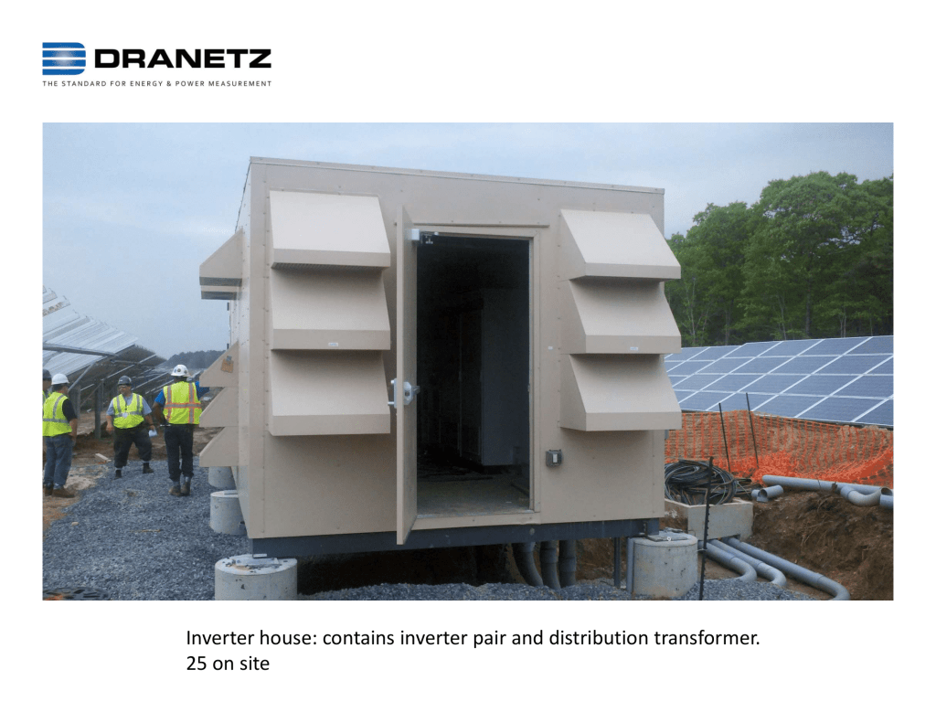
Published by Carelabs (Carelabz), Website: carelabz.com
A transfer switch’s main job is to redistribute power from a grid to a backup source of power. The control panel system of a transfer switch is what makes the unit automatic in nature. Power failures can be detected immediately with the help of automatic transfer switch (ATS) and the shift to generator power from utility power is smooth.
The control panel’s job is to detect a power failure and initiate procedures to start the new or used generator’s engine. Once the used or new generator reaches the right frequency or voltage, the control system will signal to change to generator from the normal source of power.
The Automatic Transfer Switch (ATS) is a critical piece of equipment that alternates the origin or the source of power, typically between your utility power and backup power, ensuring your system’s ability to stay online. It is inherently important in making sure that this part of your emergency system is working properly. Also, because this part of your system is usually relatively complicated in nature, they are rarely examined or tested after the ATS has left its manufacturing facility.
Why Testing of Automatic Transfer Switch Important?
It is important to determine if your ATS is within manufacturers terms in the course of a planned examination, to eliminate the risk of determining this when an unpredicted outage occurs, and you are incapable to switch your system to its secondary power.
Occasional testing of your ATS guarantees that your emergency system is dependable. Carelabs is manufacturing facilities, power plants, and industrial businesses first choice when it comes to the electrical testing of ATS’s. Our technicians and engineers are skilled on emergency systems, specifically transfer switches. With our staff’s abundant experience and training in the field contributes as a definite recipe for success.
What is Done During Automatic Transfer Switch Testing?
Few of the steps in ATS testing incudes:
- Contact to pole resistance test,
- Settings and operations verifications
- Control device Examinations
- Manufacturer’s standards and specifications checks
- Calibration services
- Tap connections resistance measurements
- Verifying engine start sequence
- Time delay and retransfer functions checks
- Mechanical parts inspections
- Anchorage and groundings review for impairment or damage
- Corresponding parts are properly lubricated and clean of debris or contaminants and many steps more.
Automatic Transfer Switch Tests Includes mainly three steps. The visual inspection, the electrical tests and the operational or functional tests:
Visual and Mechanical Inspection
- Verify mechanical and physical.
- Verify alignment, anchorage, required clearances and grounding.
- Verify the unit is clean.
- Verify appropriate lubrication on moving current-carrying parts and sliding surfaces.
- Verify that manual transfer warnings are attached and visible.
- Perform manual transfer operation.
- Check positive mechanical interlocking amid alternate and normal sources.
Electrical Tests
- With respect to ground execute insulation resistance tests on control wiring entirely.
- Perform a contact/pole-resistance test.
- Verify settings and operation of control devices.
- Calibrate and set all relays and timers.
- Check phasing, phase rotation and synchronized function as needed.
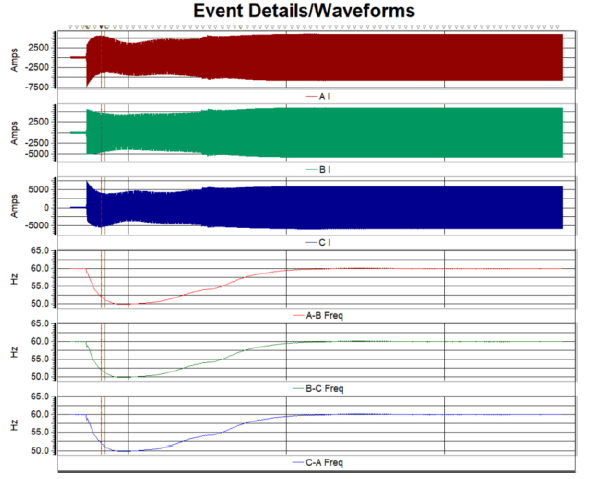
- Perform automatic transfer tests:
- Simulate loss of normal power.
- Return to normal power.
- Simulate loss of emergency power.
- Simulate all forms of single-phase conditions.
Verify correct operation and timing of the following functions
- Normal source voltage-sensing relays.
- Engine start sequence.
- Time delay upon transfer.
- Alternate source voltage-sensing relays.
- Automatic transfer operation.
- Interlocks and limit switch function.
- Time delay and retransfer upon normal power restoration.
- Engine cool down and shutdown feature.
NFPA 110 has the following rules stated in terms of Automatic Transfer Switch testing
- Operational Inspection and Testing.
- EPSSs, including all components, should be exercised under load at least monthly and inspected weekly.
- If the generator set is used for peak load shaving or for standby power, such use should be recorded and should be allowed to be replaced for scheduled functioning and testing of the generator set.
- Transfer switches shall be operated monthly.
- The periodic test of a transfer switch should constitute of electrically functioning the transfer switch till the alternate position from the standard position and returning.
How is Automatic Transfer Switch Testing Performed?
General Inspection
The inspection work should be conducted externally and internally on the transfer switch.
External Inspection
- The transfer switch should be kept in good condition by performing a weekly overall examination of the unit. This inspection must consist of inspecting for signs of excessive heat, vibration damage, any level of deterioration, any leakage or contamination.
- Any accumulations of dirt or dust must be removed. Dirt, dust and any other contaminants should always be removed from the outside and inside with a vacuum cleaner, dry cloth or brush. One should not use compressed air to blow away contaminants and dirt. This can result in debris being lodged in components resulting in damage to the switch.
- If the inspection exposes damaged or loose components contact a trained professional to perform the repair work.
- Any worn, broken or missing external sections must be substituted with manufacturer’s recommended components.
- Contact the local authorized distributor or dealer for the specific part number to order.
Internal Inspection
- All power sources must be turned OFF afore any internal inspection.
- Verify to see if any external glitches found have disturbed internal components, while opening the switch door.
- A trained service technician must be called to perform any service work. If any of the following conditions are detected:
- Dirt, dust, moisture and other contaminants accumulating on the surfaces of the unit and components
- Any signs of corrosion
- Loose, missing or broken components
- Deterioration of wiring or insulation due to cuts, abrasion or wear
- Indications of overheating due such as melted plastic, discolored metal or burning odor
- Any other evidence of damage, wear or malfunction of the transfer switch and its components
- Only a trained technician must carry out internal service work and inspection on a standby system that doesn’t permit power interruption in the course of required inspection.
Inspections beyond visual inspections
- When inspections are internal or more than just a visual inspection by the operator, they should be performed by an authorized distributor or dealer under a scheduled preventative maintenance agreement.
- Have an approved dealer or distributor replace or repair all damaged internal parts with the manufacturer’s suggested components.
Disabling the Generator Set
- Accidental starting can lead to severe injury and even death
- Safety measure must be acquired chosen to prevent the generator set starting in the course of maintenance by a remote start/stop switch, an ATS, or another remote start engine command.
- Afore operating on the generator set or any of its attached parts, like the transfer switch, detach the generator set as follows:
- Move the generator master switch to the OFF-position
- Disconnect the power to the battery charger
- Remove battery cables starting with the negative (-) lead first
Transfer Switch Automatic Control System Testing
The transfer switch automatic control system should be tested monthly. The test should verify the following:
- The necessary sequence of functioning happens when the load shifts to the emergency source which results in primary source failure
- Verify indicator LEDs on the transfer switch operates properly
- Watch and eavesdrop for any unnecessary vibration or noise in the course of operation
- Finish the test once the switch transfers the load to the standby source and check the foreseen sequence of operations happening as the transfer switch shifts the load to the primary power source and signals the generator set to turn OFF later or after a cool down period.
- Check if the time delay in the OFF position works while load is transferred to the standby source and transferred back to the favored source, in the case of systems with programmed time transitions.
Functional Test
The transfer switch functional tests comprise of electrical and manual tests. A manual operator handle is provided with the transfer switch for maintenance purposes only. Before it is operated electrically, manual operation of the switch must be checked.
A usual method of an automatic transfer switch functional test for a standby generator is explained below:
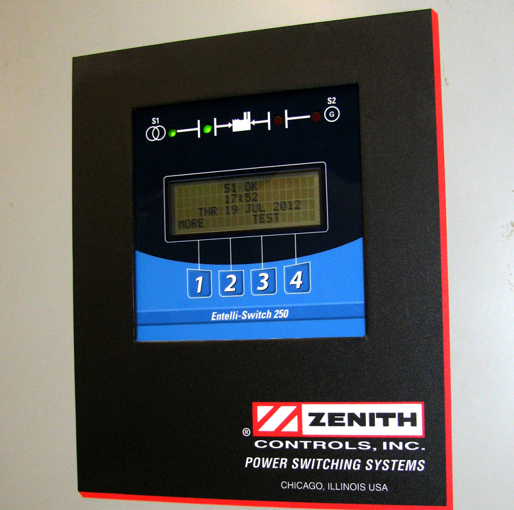
- To begin the test, close the normal source circuit breaker. The switch controller will light up the available LED when right voltage is sensed. If the source 1 stages the automatic transfer switch mechanism, the LED at source 1 will turn on. Verify the phase to phase voltages at the utility line terminals.
- Start the engine generator after closing the alternate source breaker. The S2 (Alternate) Available LED will illuminate when correct voltage and frequency levels are sensed. Turn OFF the engine generator after both sources have been validated and place the generator’s start control in the automatic position.
- Replicate a utility failure by opening the Source 1 i.e. the normal side breaker. The delay to engine start timer begins its timing cycle. After the timer has completed its timing cycle, the engine start contacts close to start the generator.
- When generator frequency and voltage touch the fixed reinstate points the Source 2 available LED lights up. Simultaneously, the delay to generator timer begins its timing cycle. When the time delay is completed the ATS will transfer to Generator, the S1 position LED goes off, and the S2 position LED illuminates. Systems shall transfer in no less than 10 seconds where failure of the equipment to perform could result in loss of human life or serious injuries.
- Reclose the Source 1 breaker to re transfer to the normal source. The delay to utility timer begins its timing cycle. When the timer has completed its timing cycle, the ATS will transfer. The S2 position LED goes off, and the S1 position LED illuminates.
- The delay engine stop timer will begin its timing cycle. The generator runs unloaded for the duration of this timing cycle. The generator will Turn OFF, once the timer finishes its timing cycle, The S2 Available LED goes off. A minimum time delay of 5 minutes should be provided for unloaded running of the EPS prior to shutdown to allow for engine cool down (NFPA 110). The minimum 5-minute delay is not required on small air-cooled prime movers 15 kW or less.
Precautions
- Inspection and Cleaning Before doing any work on the transfer switch, de-energize all sources of power.
- The switch must be checked for any moisture, dirt or dust and must be vacuumed or wiped with a soft brush or dry cloth.
- DO NOT use a blower since debris may become lodged in the electrical and mechanical components and cause damage.
- Any surface deposits must be removed with a clean cloth.
Benefits of Automatic Transfer Switch Testing
- Uninterrupted electrical supply
- Provides efficient switching to generator power
- Ensures safety
- Faster connection