Published by John Jeter, VYCON, EE Power – Industry Articles: Flywheel Energy Storage System Basics, September 23, 2021
Today, flywheel energy storage systems are used for ride-through energy for a variety of demanding applications surpassing chemical batteries.
Flywheels are among the oldest machines known to man, using momentum and rotation to store energy, deployed as far back as Neolithic times for tools such as spindles, potter’s wheels and sharpening stones. Today, flywheel energy storage systems are used for ride-through energy for a variety of demanding applications surpassing chemical batteries.
A flywheel system stores energy mechanically in the form of kinetic energy by spinning a mass at high speed. Electrical inputs spin the flywheel rotor and keep it spinning until called upon to release the stored energy. The amount of energy available and its duration is controlled by the mass and speed of the flywheel.
In a rotating flywheel, kinetic energy is a function of the flywheel’s rotational speed and the mass momentum of inertia. The inertial momentum relates to the mass and diameter of the flywheel. The kinetic energy of a high-speed flywheel takes advantage of the physics involved resulting in exponential amounts of stored energy for increases in the flywheel rotational speed.
Kinetic energy is the energy of motion as quantified by the amount of work an object can do as a result of its motion, expressed by the formula: Kinetic Energy = 1/2mv2
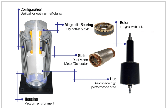
Anatomy of a High-Speed Flywheel
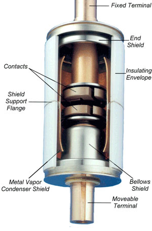
The main components of a flywheel are a high-speed permanent magnet motor/generator, fully active magnetic bearings, and rotor assembly construction (Figure 1).
1. A high-speed permanent magnet motor/generator incorporates specialized rare earth magnets to minimize rotor heating and maximize efficiency and reliability, allowing flywheel systems to cycle quickly without overheating. This facilitates use in demanding applications with high cycling and long-life requirements. The flywheel’s rotor assembly operates in a vacuum provided by an external vacuum pump. By removing air from the rotating area of the motor, all windage losses from the system are eliminated, thereby increasing electrical efficiency.
2. The flywheel incorporates a steel mass for storage. Because steel is a well-understood, well-supported material, it avoids the technology risks associated with other materials such as composites that may offer higher energy densities but with greater risks of temperature changes and creep that can cause unbalanced loads and degrade operation over time.
3. Based on a permanent magnet motor design, flywheels can continuously cycle rapidly with minimal heat. In contrast, other motor technologies generate significantly more heat during a discharge.
4. A magnetic bearing/levitation system allows the motor rotor assembly to rotate at very high speeds with no physical contact with stationary components, optimizing efficiency and product life. Magnetic bearings virtually eliminate the need for maintenance as there are no contact points within the flywheel – no bearings to replace or repack with lubricant.
5. A built-in power conversion module controller provides high efficiency and maximizes reliability over the flywheel’s operating life with self-diagnostic tools that can proactively prevent failures. For each application, flywheel rotational speed limits can be modified for appropriate cycling demands and other specific conditions.
6. Real-time display provides users with views of the flywheel status, including vital parameters such as rotor speed, charged capacity, discharge event history, and adjustable voltage settings. Additional monitoring and control capabilities are available through a serial interface, alarm status contacts, soft-start pre-charge from the DC bus and push-button shutdown.
Prime applications that benefit from flywheel energy storage systems include:
Data Centers
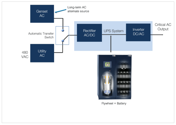
The power-hungry nature of data centers make them prime candidates for energy-efficient and green power solutions. Reliability, efficiency, cooling issues, space constraints and environmental issues are the prime drivers for implementing flywheel energy storage. Flywheels paired with a data center’s three-phase UPS units provide instantaneous and cost-efficient backup power.
During a power disruption, the flywheel will provide backup power instantly. When flywheels are used with UPS systems (instead of batteries), they provide reliable protection against damaging voltage sags and brief outages. During power disruptions and outages, the flywheel provides the energy required to maintain the load allowing enough time for the emergency generator to start and take on the load. At this time, the flywheel recharges back up to full speed ready for the next event. The leading cause of a UPS failing to support the load is battery failure. Battery life is impacted by the number of cycles, temperature and maintenance. To improve battery life and system availability, flywheels can be combined with batteries to extend battery run time and reduce the number of yearly battery discharges that reduce battery life (Figure 2).
Medical Diagnostics
Many types of medical imaging equipment, such as CT or MRI machines can also benefit from flywheel energy storage systems. Power brownouts, surges and outages can have devastating effects on MRI equipment. Often, electricity from the power substation to a hospital is not consistent for MRI and CT operations as voltage drops or surges in power can damage the unit’s refrigeration systems and prompt a hard shutdown of the MRI equipment.
Flywheels paired with the facility’s three-phase UPS systems deliver clean, reliable power to the imaging suite. If there is a power outage or the power coming in from the utility is “dirty,” the UPS will generate smooth, high-quality power from the flywheels. Besides needing the highest power reliability, space is often a concern. Due to the flywheel’s small footprint and no requirement for dedicated cooling, the UPS and flywheels can reside in the radiology suite. Conversely, a UPS with a bank of batteries would need to be located in a larger environmentally cooled area.
Renewable Microgrids
Microgrids deployed in remote installations such as islands face daunting fuel costs if diesel generators are the power source. Photovoltaic solar panels are typically employed to minimize the need for engine generators to save costs while providing cleaner, quieter power in areas such as remote resorts requiring 200 to 300kW power sources. While solar power has many advantages, solar-powered microgrids are subject to problems during demand surges as well as sags in power due to cloud cover. Adding flywheels to this type of installation can support the entire microgrid or just the solar system to prevent power quality problems resulting from sags and surges. The fluctuating nature of power problems on an unprotected solar installation can cause damage to the connected equipment, sensitive electronics such as computers and various appliances. Because the flywheel will serve as a power conditioner, absorbing these fluctuations, operators will find that connected equipment will be far less likely to fail prematurely.
A Greener Approach to Energy
As energy needs in a broad range of applications become more complex, those responsible for assuring reliable, clean, cost-effective energy supplies within their organizations are constantly looking for solutions that can increase efficiencies while enhancing energy reliability. In many cases, incorporating flywheel technology in a new or retrofit electrical system design can serve as an excellent foundation for achieving the sometimes-conflicting goals of maximizing dependability and reducing operating costs. With the added benefit of providing an environmentally friendly energy source, flywheels with a typical 20-year service life, are a clean, cost-effective solution for any application requiring “always on” power.
Author: John Jeter is the Director of Sales for VYCON, Inc. in Cerritos, Calif. John received his electronics training in the US Navy and holds a B.S. in Business from San Diego State University. He has been involved with power quality solutions for over 40 years with domestic and international experience.
Published by Sergio Panetta, International Association of Electrical Inspectors (IAEI) Magazine, Evolving Technologies – Grounding of Wind Power Systems and Wind Power Generators, May 16, 2010
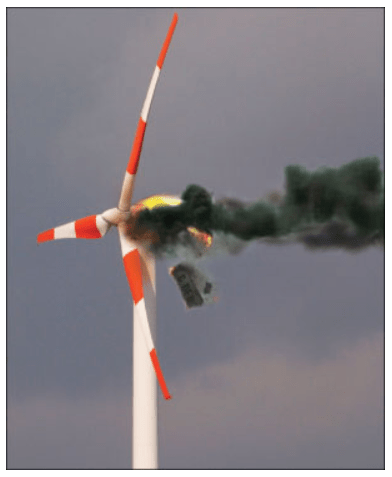
Power continuity is essential in wind power projects where a tripped overcurrent device due to ground fault can have serious economic or operational consequences. An arcing phase-to-ground fault can totally destroy the equipment. Consequential downtime adds to the economic loss. Four typical grounding methods for generators and power systems are examined for these factors and the article concludes that resistance grounding provides the best protection against arcing ground-fault damage in wind power projects with distribution systems and improves reliability and availability of the power systems.
Photo 1. Wind Turbine Fire
Grounding of Generators
The generators can be ungrounded, high-resistance grounded, low-resistance grounded or solidly grounded. In solidly grounded generators, very high fault currents can flow in the event of a phase-to-ground fault with a possibility of extensive fault damage[4]and consequential loss of revenue. In addition, there is a possibility of high harmonic current flows when the generator and step-up transformers are solidly grounded. Applying low-resistance grounding reduces the potential damage due to phase-to-ground faults, but the generator must be tripped and isolated with a consequential loss of revenue. With high-resistance grounding, a phase-to-ground fault can be annunciated[4]and the generator kept running. An ungrounded generator can be used if the cable length to the step-up transformer is relatively small. With long cable lengths in multiple generator systems, the generator to transformer section becomes susceptible to transient overvoltages in case of intermittent phase-to-ground faults. This could lead to subsequent 2ndphase-to-ground failure elsewhere in the network leading to catastrophic damage.
Power Collection System
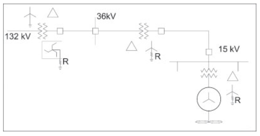
Figure 1. Single generator to transformer
The transformer secondary is usually connected in delta and can be 5, 15, or 36 kV for areas which follow ANSI specifications, and 3.3, 11, 20, or 33 kV for areas following IEC specifications.
This arrangement can be a single generator to transformer, as shown in figure 1 or multiple generators to a transformer, as shown in figure 2. Power is collected through many such transformers on a wind farm in the medium voltage (MV) distribution network, and exported to the utility network at the point of common coupling, as shown in figure 3.[2]
MV Circuits
Figure 2. Multiple generators to a transformer
Solidly grounded circuits lead to high-fault currents due to phase-to-ground faults and may cause extensive damage and high-step or touch voltages. Low-resistance grounding thus lowers the phase-to-ground fault current and allows time-current coordinated trips to isolate the faulty circuit. High-resistance grounding is not suggested, since the cable capacitance can be quite high due to the total length of the MV cable at the collection voltage. When the MV network is left ungrounded on the occurrence of a phase-to-ground fault, the voltage on the other two phases to ground rises to phase-to-phase value, but the operation of the wind farm remains uninterrupted.[3]
An ungrounded MV network is subjected to transient overvoltages on the two healthy phases in the case of intermittent or arcing type phase-to-ground faults, due to the capacitive charge build-up in the cables.
MV Electrical Distribution Networks
Wind farm collection networks are simple radial circuits with switching devices for isolation and switching.[1]Balanced 3-phase networks are suitable for connecting large wind generators. The secondary of the generator step-up transformer can be Y- or Delta-connected. In Y-connected transformers the neutral point is directly accessible and hence can be easily grounded. In Delta-connected transformers an accessible neutral point is created by using a grounding transformer as shown in figure 4. The usual practice is to ground the neutral point at one location only.
Figure 3. MV Collection Network
Electrical Protection
With high-resistance grounding of the generator step-up transformer, fast acting ground-fault relays can be applied in the generator circuit. Low-resistance grounding by neutral grounding resistors or artificial neutrals is suggested for the MV network. The fault currents in the MV collection networks can be small due to high source impedance and long lengths of cables. In some cases, fuses cannot be relied upon to quickly clear the fault; hence, ground-fault relays and circuit breakers are required. It is important to isolate the faulted section quickly. Correct discrimination is obtained by the application of ground-fault relays.
Figure 4. MV collection network with artificial neutral
Additional Electrical Protection
Photo 2. Wind Turbine Fire
Conclusion
Ungrounded delta systems have many operating disadvantages, including high transient overvoltages and difficulty in locating faults. Solidly grounded neutral systems limit the system potential to ground, and speed the detection and location of ground faults. However, the system must be shut down after the first ground fault and there is a potential for extensive arcing fault damage. Applying coordinated ground-fault protection is very difficult and almost impossible with multiple generators.
Low-resistance grounded neutral systems limit the magnitude of the ground-fault current so that serious damage does not occur. The system must still be shut down after the first ground fault. This level of resistance grounding is generally used on medium- and high-voltage systems, above 6.9 kV.
If the power system is changed to high-resistance grounding then the ground-fault current can be reduced to 10 A or less, which has significant impact on reducing the equipment damage. In addition, it ensures that the wind power system continues to operate and does not suffer trip-out of a faulted generator.
Published by Electrical Installation Wiki, Chapter J. Overvoltage protection – Surge protection Application examples
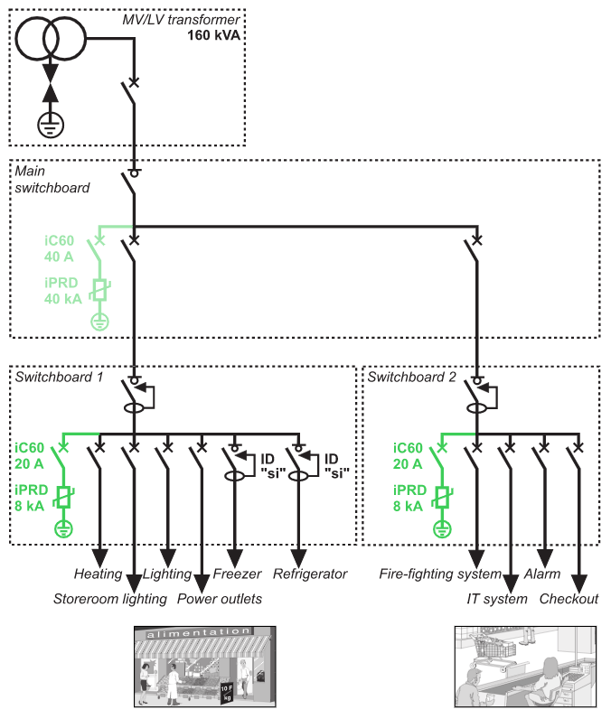
SPD application example in Supermarket
Fig. J45 – Application example: supermarket
Solutions and schematic diagram
• The surge arrester selection guide has made it possible to determine the precise value of the surge arrester at the incoming end of the installation and that of the associated disconnection circuit breaker.
• As the sensitive devices (Uimp < 1.5 kV) are located more than 10m from the incoming protection device, the fine protection surge arresters must be installed as close as possible to the loads.
•To ensure better continuity of service for cold room areas: ∙ “si” type residual current circuit breakers will be used to avoid nuisance tripping caused by the rise in earth potential as the lightning wave passes through.
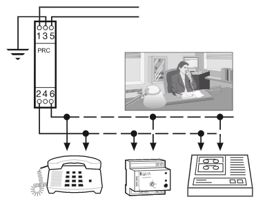
• For protection against atmospheric overvoltages: ∙ install a surge arrester in the main switchboard ∙ install a fine protection surge arrester in each switchboard (1 and 2) supplying the sensitive devices situated more than 10m from the incoming surge arrester ∙ install a surge arrester on the telecommunications network to protect the devices supplied, for example fire alarms, modems, telephones, faxes.
Cabling recommendations
• Ensure the equipotentiality of the earth terminations of the building. • Reduce the looped power supply cable areas.
Installation recommendations
• Install a surge arrester, Imax = 40 kA (8/20 µs) and a iC60 disconnection circuit breaker rated at 40 A.
• Install fine protection surge arresters, Imax = 8 kA (8/20 µs) and the associated iC60 disconnection circuit breakers rated at 10 A
Fig. J46 – Telecommunications network
SPD for photovoltaic applications
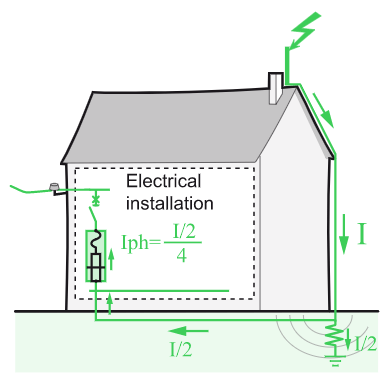
Overvoltage may occur in electrical installations for various reasons. It may be caused by:
• The distribution network as a result of lightning or any work carried out. • Lightning strikes (nearby or on buildings and PV installations, or on lightning conductors). • Variations in the electrical field due to lightning.
Like all outdoor structures, PV installations are exposed to the risk of lightning which varies from region to region. Preventive and arrest systems and devices should be in place.
Protection by equipotential bonding
The first safeguard to put in place is a medium (conductor) that ensures equipotential bonding between all the conductive parts of a PV installation.
The aim is to bond all grounded conductors and metal parts and so create equal potential at all points in the installed system.
Protection by surge protection devices (SPDs)
SPDs are particularly important to protect sensitive electrical equipments like AC/DC Inverter, monitoring devices and PV modules, but also other sensitive equipments powered by the 230 VAC electrical distribution network. The following method of risk assessment is based on the evaluation of the critical length Lcrit and its comparison with L the cumulative length of the d.c. lines.
SPD protection is required if L ≥ Lcrit .
Lcrit depends on the type of PV installation and is calculated as the following table (Fig. J47) sets out:
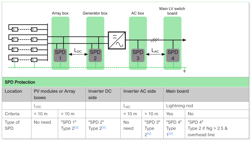
Fig. J47 – SPD DC choice
L is the sum of:
• the sum of distances between the inverter(s) and the junction box(es), taking into account that the lengths of cable located in the same conduit are counted only once, and • the sum of distances between the junction box and the connection points of the photovoltaic modules forming the string, taking into account that the lengths of cable located in the same conduit are counted only once.
Ng is arc lightning density (number of strikes/km2/year).
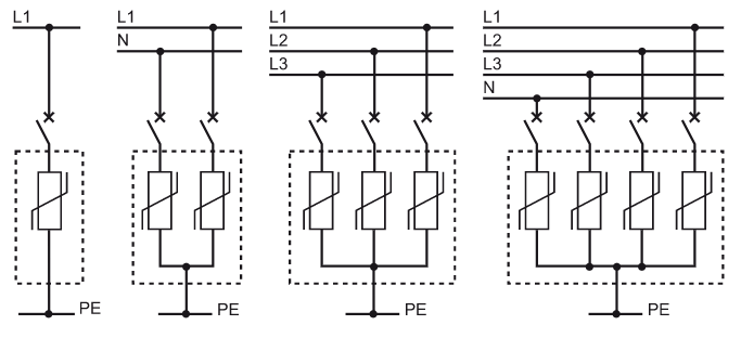
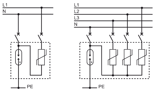
Fig. J48 – SPD selection
a. ^1 2 3 4 Type 1 separation distance according to EN 62305 is not observed.
Installing an SPD
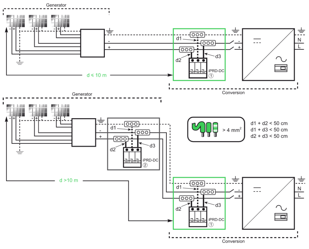
The number and location of SPDs on the DC side depend on the length of the cables between the solar panels and inverter. The SPD should be installed in the vicinity of the inverter if the length is less than 10 metres. If it is greater than 10 metres, a second SPD is necessary and should be located in the box close to the solar panel, the first one is located in the inverter area.
To be efficient, SPD connection cables to the L+ / L- network and between the SPD’s earth terminal block and ground busbar must be as short as possible – less than 2.5 metres (d1+d2<50 cm).
Safe and reliable photovoltaic energy generation
Depending on the distance between the “generator” part and the “conversion” part, it may be necessary to install two surge arresters or more, to ensure protection of each of the two parts.
Published by Ark Tsisserev, International Association of Electrical Inspectors (IAEI) Magazine, Canadian Perspectives – Grounding and Bonding — New Questions and Answers, July 1, 2021
Although Section 10 of the Canadian Electrical Code, Part I (CE Code), which applies to grounding and bonding, has been re-written in the 2018 edition of the Code, I keep receiving questions from the readers regarding the fundamentals of grounding and bonding.
In this article, I’ll share with the readers eight questions (which is usually enough) on this subject and will provide the answers based on the requirements of Section 10 of the CE Code.
Question #1. What is an “electrical system.”
Answer to question # 1. An electrical system is a complete electrical installation in which the electric energy is provided by a single energy source to the utilization equipment via a distribution network. A typical example of such a source for an electrical system could be a secondary winding of a transformer, a generator, a battery, a photovoltaic module, a fuel cell, a hydrokinetic turbine generator, etc. For example, an electrical installation supplied from a transformer or bank of transformers can be considered an electrical system; installation supplied from a different transformer, or a generator would be considered a different electrical system.
When a 347/600 V electrical system supplies a 600 V:120/208 V transformer, then primary winding (usually “delta” connected) of this transformer represents a load, similarly to a heating or motor load, but the secondary (120/208 V “Wye” connected) winding represents a source of a new 120/208 V electrical system.
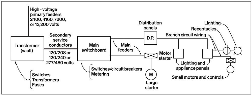
A typical single-line diagram of a building electrical distribution system is shown in figure 1.
Figure 1. Typical single line diagram of a building electrical distribution system
Question #2. When is an electrical system required to be solidly grounded?
Answer to question #2. Subrule 10-206(1) of the CE Code states the following:
“10-206(1) AC systems exceeding extra-low voltage shall be solidly grounded if
1. a) by doing so, their maximum voltage-to-ground does not exceed 150 V; or 2. b) the system incorporates a neutral conductor.”
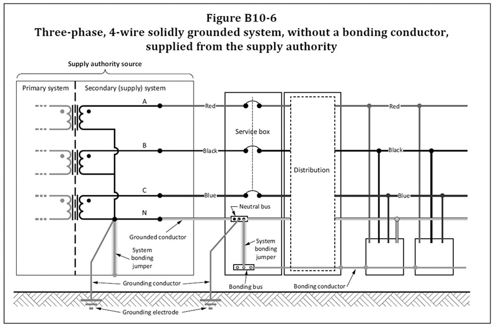
It means that if an electrical system has a voltage to ground not more than 150 V (i.e., a typical 120/240 V, single-phase, 3-wire system, or a typical 120/208 V 3 phase, 4-wire system), then the safety objective for solid grounding connection of such electrical system and objective for bonding of metal non-current carrying parts of electrical equipment supplied by such system, is to protect the users by establishing a low impedance path between the grounded conductor and the non-current carrying conductive parts of the system – to stabilize system voltage and to facilitate the operation of protective devices.
It also means that if an electrical system incorporates a neutral conductor, such a system also must be solidly grounded.
Figure B10-6 from the 2021 CE Code. Courtesy of CSA Group.
Question #3: What is the system bonding jumper?
Answer to question # 3: System bonding jumper — a conductor that interconnects the system grounded point with the non-current carrying metal enclosure of the source and interconnects the neutral conductor coming from the source to the service equipment with the non-current carrying metal enclosure of the service equipment.
Clause 6.9 of the CSA safety standard C22.2 No. 0.19 “Requirements for service entrance equipment” clarifies that the neutral conductor coming from the source of a solidly grounded system to the service equipment would have to be terminated in the neutral assembly, provided with a sufficient number of connectors, and that one of such connectors, must be used for connection of the system bonding jumper to the enclosure of service equipment [see item (d) in Clause 6.9]:
“6.9
Equipment intended to function as service equipment for solidly grounded systems involving a neutral or other grounded service conductor shall be provided with a neutral assembly located within the service-disconnecting compartment. The neutral assembly shall be provided with an adequate number of suitable pressure-terminal connectors, clamps, or other approved means for connecting the following:
(a) the incoming (grounded) neutral conductor; (b) the corresponding outgoing (neutral) conductor, if any required; (c) the grounding conductor; (d) the bonding conductor to the enclosure; (e) the bonding conductor to the metal service raceway.”
Question #4. Is a grounding conductor allowed to be connected to the metal non-current carrying enclosure of the service equipment?
Answer to question #4. In a solidly grounded system, a grounding conductor must be connected only to a grounded service conductor (to a neutral conductor brought to the service equipment from the solidly grounded power supply source). Item 6.9(c) in standard C22.2 No. 019 (see text immediately above) clearly articulates this fact.
Rule 10-210(a) of the CE Code, Part I also provides this requirement as follows:
“10-210 Grounding connections for solidly grounded ac systems supplied by the supply authority (see Appendix B)
The grounded conductor of a solidly grounded ac system supplied by the supply authority shallbe connected to a grounding conductor at one point only at the consumer’s service…. “
Only a system bonding jumper must be connected to the enclosure of service equipment when a solidly grounded system is provided by the supply authority. (see Figure B10-6 of the CE Code, Part I):
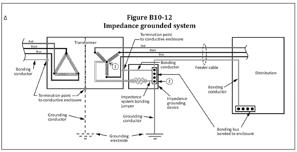
If, however, an impedance grounded system or ungrounded system is provided, then a grounding conductor is permitted to be connected to the metal, non-current carrying enclosure of the service equipment (see Figures B10-12 and B10-13 of the CE Code, Part I).
Figure B10-12 from the 2021 CE Code. Courtesy of CSA Group.
Figure B10-13 from the 2021 CE Code. Courtesy of CSA Group.
Question #5: What does a single point grounding mean?
Answer to question # 5: It means that the connection of a solidly grounded system to a grounding electrode via a grounding conductor must be made at a single point only so, that there is no objectionable passage of current over the grounding conductors. Ideally, such single-point grounding should be at the source of every newly derived solidly grounded system. However, when such solidly grounded system is provided by the power supply authority/electric utility (it should be noted that installations by utilities are outside the scope of the CE Code), such single-point grounding of the solidly grounded system must be established (in addition to the grounding of this system by the power supply authority/utility), at the service equipment/service box, see Figure B10-6 and Rule 10-210 of the CE Code:
“10-210 Grounding connections for solidly grounded ac systems supplied by the supply authority (see Appendix B) The grounded conductor of a solidly grounded ac system supplied by the supply authority shall a) be connected to a grounding conductor at one point only at the consumer’s service; b) have a minimum size as specified i) for a bonding conductor; and ii) for a neutral conductor when the grounded conductor also serves as a neutral; c) be connected to the equipment bonding terminal by a system bonding jumper; and d) have no other connection to the non-current-carrying conductive parts of electrical equipment on the supply side or the load side of the grounding connection.“
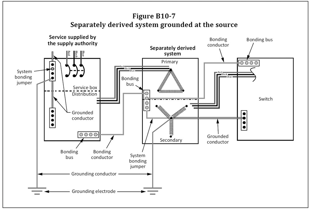
If in addition to the solidly grounded system supplying a building, another (separately derived) solidly grounded system is created in the building (i.e., if, for example, the 347/600 V solidly grounded system supplies the building, and a new separately derived 120/208 V solidly grounded system is created on the secondary “Y” connected winding of a stepdown transformer), this new, separately derived solidly grounded system must have a single point of grounding at the source of this system, or at the first switch controlling the system. (see Figures B10-7 and B10-8 of the CE Code):
Figure B10-7 from the 2021 CE Code. Courtesy of CSA Group.
Figure B10-8 from the 2021 CE Code. Courtesy of CSA Group.
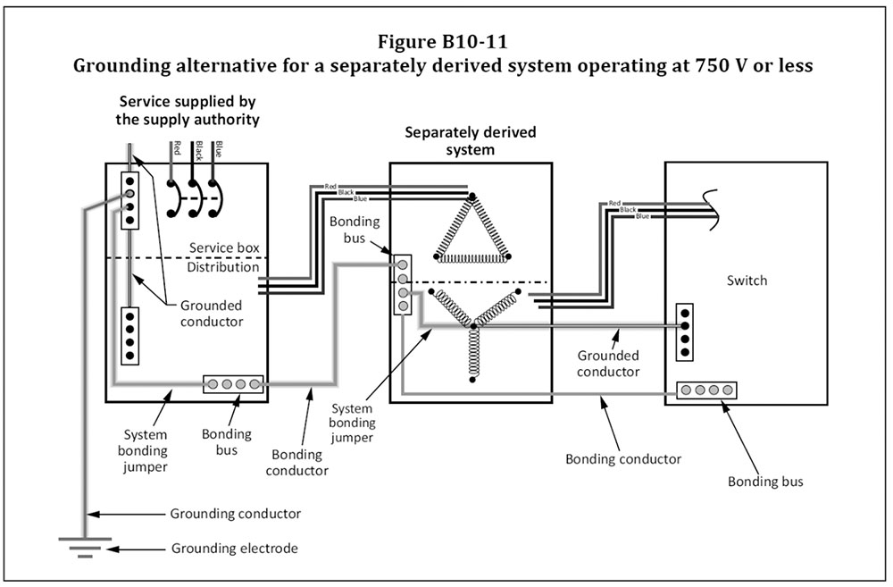
However, Subrule 10-212(2) allows an exception from this requirement. See Subrule 10-212(2) and Figure B10-11:
“10-212 Grounding connections for solidly grounded separately derived ac systems (see Appendix B)
1) Except as permitted by Subrule 2), the grounded conductor of a solidly grounded separately derived ac system shall
a) be connected to the equipment bonding terminal by a system bonding jumper i) at the source; ii) at the first switch controlling the system; or iii) at the tie point, where two or more systems terminate at a tie point; b) be connected to a grounding conductor at the same point on the separately derived system where the system bonding jumper is connected; and c) have no other connection to the non-current-carrying conductive parts of electrical equipment on the supply side or the load side of the grounding connection.
2) A separately derived ac system operating at 750 V or less shall be permitted to be grounded by the system bonding jumper that is connected to the bonding conductor included in the primary supply.“
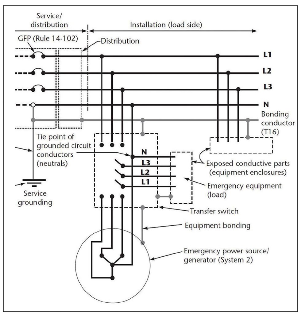
If a separately derived solidly grounded system is provided not in addition to the main solidly grounded system supplying the building, but as an alternative to this main system (i.e., provided by a generator), and a neutral is not interrupted by the automatic transfer switch, then the neutral of the solidly grounded system derived by the generator may be connected to the grounding electrode via a grounding conductor established at the service of the main solidly grounded system (see diagram in figure 8):
Figure B10-11 from the 2021 CE Code. Courtesy of CSA Group.
Question #6: How is a system bonding jumper sized?
Answer to question # 6: The size of the system bonding jumper (and the bonding conductor) installed at the service equipment must be based on the ampacity of ungrounded service conductors.
Subrule 10-616(2) clarifies this subject as follows:
“10-616(2) The size of a bonding conductor installed in accordance with Rule 10-604 at service equipment shall not be less than that determined in accordance with Table 16 based on the allowable ampacity of the largest ungrounded conductor.“
Question #7: How to size a grounding conductor?
Answer to question # 7: Sub rule 10-114(1) of the CE Code provides the following requirement on this subject:
“10-114 Grounding conductor size (see Appendix B) 1) Except as permitted by Subrule 2), the grounding conductor shall be sized not smaller than a) No. 6 AWG if of copper; or b) No. 4 AWG if of aluminum.”
Figure 8. From Appendix B Notes on 2015 edition. Courtesy of CSA Group.
Question #8: Why is the size of a grounding conductor smaller than the size of a system bonding jumper?
Answer to question # 8: The system bonding jumper is a part of the bonding system which consists of non-current carrying metal enclosures of electrical equipment, interconnected by bonding conductors which will carry fault current back to the source of the solidly grounded system via a system bonding jumper at the service equipment and the grounded service conductor.
The primary function of the grounding conductor is to establish a common reference to ground and to create an equipotential plane by connecting the grounded service conductor with earth.
The size of a grounding conductor for a solidly grounded system does not have to be larger than No. 6 AWG copper or No. 4 AWG aluminum, as the grounding conductor carries only a very small portion of the fault current back to the source via a parallel fault path, and this small portion of the fault current depends on the total impedance of the grounding circuit, including the earth resistance. As the ampacity of the grounded service conductor (neutral) is sufficient to carry the fault current for the entire duration of a fault, the size of the grounding conductor is almost irrelevant for the purpose of its role in mitigating faults.
Of course, in high voltage installations, where a station ground electrode is required in accordance with Section 36 of the CE Code, sizing of station ground electrode conductors and sizing of conductors connecting all non-current carrying metal equipment and structures to the station ground electrode would have to comply with Rules 36-302 and 36-308 of the CE Code, Part I, as Section 36 supplements or amends general provisions of Section 10.
Hopefully, answers to the posted eight questions clarify this interesting and important subject. However, as usual, the authority having jurisdiction for the administration of the CE Code should be consulted in respect to each installation.
Author: Ark Tsisserev is president of EFS Engineering Solutions, Ltd., an electrical and fire safety consulting company, and is a registered professional engineer with a master’s degree in Electrical Engineering. Prior to becoming a consultant, Ark was an electrical safety regulator for the city of Vancouver. He is currently the chair of the Technical Committee for the Canadian Electrical Code and represents the CE Code Committee on the CMP-1 of the National Electrical Code. Ark can be reached by e-mail at: ark.tsisserev@efsengineering.ca His company web site is: http://www.efsengineering.ca
Published by Anna KOZIOROWSKA1,2, Dariusz SOBCZYŃSKI3, Wiesława MALSKA3 Uniwersytet Rzeszowski, Wydział Matematyczno – Przyrodniczy, Instytut Techniki (1) Uniwersytet Rzeszowski, Centrum Biotechnologii Stosowanej i Nauk Podstawowych (2) Politechnika Rzeszowska, Wydział Elektrotechniki i Informatyki, Katedra Energoelektroniki i Elektroenergetyki (3)
Abstract: Specialized biomedical laboratory equipment, very often use power converters, which are a source of higher harmonics. These devices depending on their functions consist of several additional elements (e.g.: UV lamp, heater),and give the possibility of speed control. These devices are most often used in analytical laboratories and research biomedical and biotechnological laboratories.
Streszczenie. Specjalizowane biomedyczne urządzenia laboratoryjne, bardzo często wykorzystują przekształtniki energoelektroniczne, które są źródłem wyższych harmonicznych. Urządzenia te w zależności od swoich funkcji składają się z kilku dodatkowych elementów (np.: lampa UV, grzałka), a dają możliwość regulacji prędkości. Urządzenia tego typu stosowane są najczęściej w laboratoriach analitycznych oraz w biotechnologicznych laboratoriach naukowo-badawczych. (Badania biomedycznych urządzeń laboratoryjnych pod kątem generacji zakłóceń)
Słowa kluczowe: odkształcenia napięcia i prądu, wyższe harmoniczne, urządzenia laboratoryjne Keywords: Voltage and Current Distortion, Higher Harmonics, biomedical laboratory equipment
Introduction
Converters AC/DC are now widely used in many fields of technology, ranging from households and business services to industry, power generation, ending on telecommunications, the aerospace. The purpose of power converters using in consumer devices is mainly the reduction of energy consumption and lower operating costs. There is also important the construction and appropriate control of power electronic devices that from the point of view of the power supply network reduce the negative impact of this type of power converters on the power supply network [1,2,3,4]. This paper presents the results of measuring tests of influence on supply network of ultracentrifugation and electrophoresis system [5,6,7,8,10,11].
The study was conducted in the laboratory of the Institute of Applied Biotechnology and Basic Sciences University of Rzeszow in Werynia.
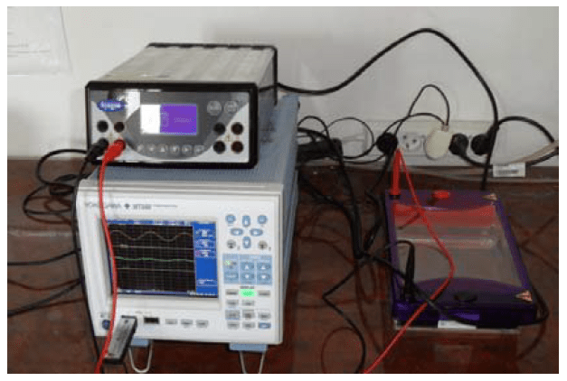
Photo 1. Electrophoresis system
Characteristics of laboratory equipment
The phenomenon of electrophoresis is the movement of charged particles relative to the solvent under the influence of the applied electric field. Areas of application of electrophoresis phenomenon are biochemistry of nucleic acids and proteins, molecular biology, and medical diagnostics [9]. An example of the application of this phenomenon is the DNA electrophoresis, which allows separation of particles due to their volume. DNA moves in the electric field and the applied gel resists proportional to particle size. Different particles move at different speeds – small rapidly, and large slowly. There are formed stripes, the groups of molecules of the same size. In the laboratory of Center of Applied Biotechnology and Basic Sciences there is installed the electrophoresis kit, which was tested for the impact of nonlinear devices on the quality of electric energy (photo 1).
Centrifugal extractors are popular devices used in analytical laboratories for the separation of mixtures into components of different densities. They are used in research of genetic engineering. They can be used in microbiology laboratories, biochemical, clinical and industrial applications. Due to the fast rotation of the fluid it is possible to separate the lighter components from the heavier. Heavier components will be located away from the axis of rotation. Due to the speed of rotation centrifugal extractors can be divided into three groups: low speed at up to 5 000 rpm, medium speed – up to 20 000 rpm and ultra speeds of more than 20 000 rpm.
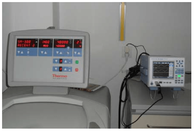
Photo 2. Ultracentrifuge
In the study there was used the centrifuge Thermo Scientific Sorvall Legend. It is dedicated to the cell culture, bioproduction and separation of blood cells. Cooling systems used in the centrifuge allows to control the temperature of the sample and the chamber between -10°C and +40°C. Maximum speed is 12 000 rpm, and the power of 1400 W. There is used brushless induction motor drive in the centrifuge. There were made the measurement tests of currents and voltages of Thermo Scientific Sorvall Evolution and its influence on quality of electric energy. This device is designed for high performance samples and is used very often in specialized laboratories.
Results of measurement tests
In order to analyze the work of selected biomedical laboratory equipment in terms of their impact on the supply network there were measured selected parameters at the Laboratory of Biotechnology in Institute of Applied Biotechnology and Basic Sciences. Laboratory equipment is used for scientific research in the field of biotechnology. As the evaluation measure of harmonic distortion factor there were adopted the factor of harmonic content THD (Total Harmonic Distortion) and individual distortion factor HD (Individual Harmonic Distortion) [8,10].
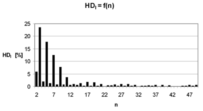
Individual Harmonic Distortion of centrifuge current (Fig. 2), shown in Figure 1 for standby operating status and temperature inside the centrifuge equal 4°C indicates a not very large deformation of the supply current, and the value of THD for the current is 9.97% (THD value of the voltage is 1.73%).
Fig.1. Individual Harmonic Distortion of current fed the centrifuge (standby operation state)
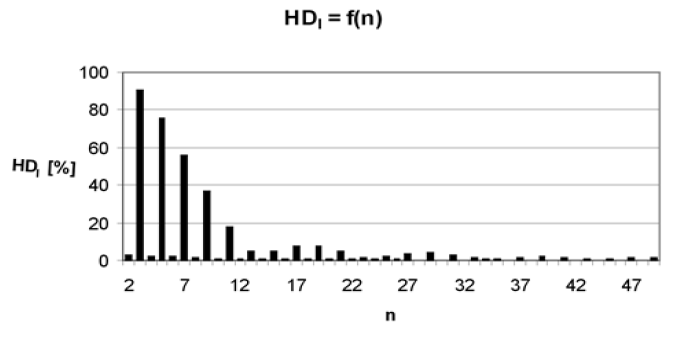
Fig.2. Individual Harmonic Distortion of current supplying centrifuge (operating state at 12 000 rpm and lowering the temperature inside the centrifuge)
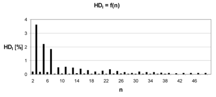
Fig.3. Individual Harmonic Distortion of current supplied centrifuge (fixed operations state, speed equal to 12 000 rpm and a fixed temperature inside the chamber of 4°C)
Figure 2 shows a ratio of HD for operating state with a fixed rotation speed equal to 12 000 rpm and operating of the refrigerator in order to reduce the temperature inside the centrifuge chamber to 4°C. For this case there was measured THD ratio of current equal to 33.8% (the value of the voltage THD was 2.25%). For a fixed centrifuge operation at a speed equal to 12 000 rpm and a fixed temperature of 4°C, there was a significant increase in the HD coefficient – fig. 3, which is also reflected in the current THD – equal in this case 137% (the value of the voltage THD was 2.17%).
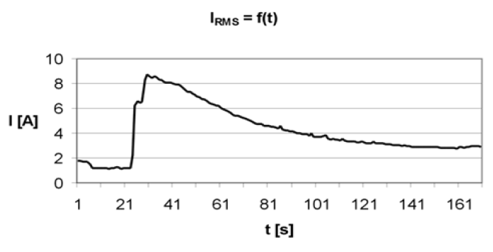
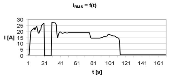
Figures 4-6 show the waveforms of RMS current drawn by the centrifuge at different operating conditions, start from preparation to operation, by operation and cooling the chamber to 4°C, and from the start to the normal, stable operation at a speed of 12 000 rpm. Figure 4 shows the course of the RMS current of centrifuge over 170 seconds (start-up from standby to start centrifugation at 12 000 rpm, stop and restart). Waveforms allow for the classification of this biomedical laboratory equipment to a group of “Anxious” receivers.
Fig.4. Course of RMS current of centrifuge within 170 seconds (start-up from standby to start centrifugation at 12 000 rpm, stop and re-start)
Figure 5 shows the course of RMS current centrifuge within 170 seconds – from start-up status to stable operation at a speed of 752 rpm, for operating conditions on the first stage of speed control.
Fig.5. Course of RMS current of centrifuge within 170 seconds (start and work on the first stage of speed control with a maximum speed of 752 rpm)
Figure 6 shows the course of RMS current of the centrifuge within 170 seconds. Lists the states of the centrifuge operation from starting and running the fifth stage of centrifugation speed control, ensures the spin speed 9 000 rpm, then turn off the device, restart, work and stop of the centrifuge.
Fig.6. Course of RMS current of the centrifuge within 170 seconds (start and work on the fifth stage of speed control with rotation of 9 000 rpm, power off, restart, work and stop the centrifuge)
For ultracentrifuge, which provides the spin speed to 60 000 rpm HD-value is very low. There is a low value of current THD too, it is equal 6,32%. For the case of Figure 7 the value of the voltage THD is 1.9%. And for the case of Figure 8 current THD equals 4.76% (the value of the voltage THD was 1.85%), reflecting the reduced negative impact of this type of devices on the power supply. Presented in Figures 7-8 individual harmonic distortion HD of the supply current of the ultracentrifuge confirms the high class of device and very low negative impact on the supply network. Harmonic amplitudes have also low values.
Fig.7. Individual Harmonic Distortion of current supplying the ultracentrifuge (starting of the device)
Fig.8. Individual Harmonic Distortion of current supplying the ultracentrifuge (fixed operating state at a rotation speed 40 000 rpm)
Fig.9. Course of RMS current of the ultracentrifuge within 170 seconds (startup of the device, than set of the speed settings)
Fig.10. Course of RMS current of ultracentrifuge within 170 seconds (gradual starting of the device on the top step of startup decrease of voltage value to 212 V at RMS current 19 A)
RMS current waveforms of the ultracentrifuge from the start operation state and set of the parameters of working up to the start-up and normal operation within 170 seconds are shown in Figure 9 This type of centrifuge is a device with a capacity of 3.5 kW, hence the large value of the current during the operation state.
In Figure 10 there is shown the gradual start-up of the device. On the top step of startup voltage decreased to a value of 212 V at RMS current 19 A. After startup there was a normal stable operation state with maintaining ultracentrifuge speed settings and keeping the recommended temperature inside the chamber.
There is interesting centrifuge stops in safe mode in 93 second of observation at a rotation speed 40 000 rpm restart, and normal operation state, shown in Figure 11.
Fig.11. Course of RMS current of ultracentrifuge within 170 seconds (start-up, normal operation, emergency stop of the centrifuge at a speed of 40 000 rpm, standby and restart)
Fig.12. Course of RMS current of ultracentrifuge within 170 seconds (normal operation at a speed of 40 000 rpm and stop in the normal mode)
Fig.13. Course of RMS current of the ultracentrifuge within 170 seconds (normal operation at a speed of 40 000 rpm and stopping at “Normal” operating mode and restart, work and stopping)
Fig.14. Course of RMS current of electrophoresis system within 170 seconds (normal operation state at voltage 70V and current 93 mA)
Fig.15. Course of RMS current of electrophoresis system within 170 seconds (normal operation state at voltage 200 V and current 300 mA)
Fig.16. Individual Harmonic Distortion of current supply electrophoresis system (normal operation at voltage 200 V and current 300 mA)
Shown in Figure 12 stopping of ultracentrifuge in “normal” mode in 75 second of observation at a rotation speed 40 000 rpm until the stop provides a very good design of control and regulation system. However, Figure 13 shows the course of RMS current of ultracentrifuge within 170 seconds from start-up and normal operation at a speed of 40 000 rpm and stop at “Normal” operating mode, restart, work and stop.
Among the analyzed biomedical laboratory equipment with the lowest power was kit for electrophoresis (photo 1). In Figures 14-15 there are presented the courses of RMS current of the electrophoresis system for two different load levels of the device.
Electrophoresis system dependency of individual supply current distortion in a normal operating state and voltage at 200 V and 300 mA is shown in Figure 16. For these conditions the value of current THD is 23.9% (the value of the voltage THD was 1.74%).
Summary
Based on laboratory tests, using a power meter Yokogawa WT 500 there can be evaluated the level of harmonics generated to the power system by a specialized biotechnological laboratory equipment. The results for ultracentrifuge suggest high class of the device and very low negative impact on the power network. Electrophoresis system has larger negative impact on the supply network, but it is a low-power electrical device which specific work is differs significantly from the dynamic specific work of the ultracentrifuge. Both tested devices affect on parameters of power supply network, but has little effect on other electric devices fed from the same power network. All tests shown in the paper will help to design the filter to reduce the higher harmonics generation
The study was performed within the project Centre of Applied Biotechnology and Basic Sciences supported by the Operational Programme Development of Eastern Poland 2007-2013, NoPOPW.01.03.00-18-018/09.
REFERENCES
[1] Barlik R., Nowak M.: Jakość energii elektrycznej – stan obecny i perspektywy. Przegląd Elektrotechniczny , nr 7-8 2005, [2] Hanzelka Z.: Rozważania o jakości energii elektrycznej. Elektroinstalator nr 9/2001- 2/2002 [3] Malska W., Łatka M.: Wpływ odbiorników nieliniowych na parametry jakości energii elektrycznej, Wiadomości Elektrotechniczne, nr 10, 2007r. [4] Nowak M., Barlik R.: Poradnik inżyniera energoelektronika, WNT, Warszawa 1998 [5] Paice Derek A.: Power electronic converter harmonics, IEEE Press, New York 1996 [6] Piróg S.: Energoelektronika: układy o komutacji sieciowej i o komutacji twardej), Uczelniane Wydawnictwa Naukowo-Dydaktyczne, AGH, 2006 [7] Strzelecki R., Supronowicz H.: Filtracja harmonicznych w sieciach zasilających prądu przemiennego, Postępy Napędu Elektrycznego, 1998 [8] Ustawa z dnia 10 kwietnia 1997 r. Prawo energetyczne. Dz.U. nr 54, poz. 348 z późniejszymi zmianami [9] Kalinowska K., Ogórek R., Baran E. – Diagnostyka mikologiczna: wczoraj i dziś. Od mikroskopu do termocyklera, Mikologia Lekarska 2011, 18 (3): 156-158 [10] Bartman J., Koziorowska A., Kuryło K., Malska W. – Analiza rzeczywistych parametrów sygnałów elektrycznych zasilających układy napędowe pomp wodociągowych – Przegląd Elektrotechniczny, 2011/8, str. 8-11 [11] Norma PN-EN/50160 Parametry napięcia zasilającego w publicznych sieciach rozdzielczych. PKN 1998 [12] Rozporządzenie ministra gospodarki i pracy z dnia 20 grudnia 2004 r. w sprawie szczegółowych warunków przyłączenia do sieci elektroenergetycznych, ruchu i eksploatacji tych sieci. Dz.U. z 06.01.2005 [13] PN-EN 50160:2002 Parametry napięcia zasilającego w publicznych sieciach rozdzielczych. [14] PN-T-03501:1998 Kompatybilność elektromagnetyczna (EMC). Dopuszczalne poziomy. Ograniczanie wahań napięcia i migotania światła powodowanych przez odbiorniki o prądzie znamionowym większym niż 16 A, w sieciach zasilających niskiego napięcia. [15] [10] PN-EN 61000-3-2:1997 Kompatybilność elektromagnetyczna (EMC). Dopuszczalne poziomy. Dopuszczalne poziomy emisji harmonicznych [16] prądu (fazowy prąd zasilający odbiornika mniejszy lub rowny 16 A). [17] PN-EN 61000-3-3:1997/A1:2002 (U) Kompatybilność elektromagnetyczna (EMC). Dopuszczalne poziomy. Ograniczanie wahań napięcia [18] [12] PN-EN 61000-4-7:1998 Kompatybilność elektromagnetyczna (EMC). Metody badań i pomiarow. Ogólny przewodnik dotyczący pomiarowharmonicznych i interharmonicznych oraz stosowanych do tego celu przyrządow dla sieci zasilających i przyłączonych do nich urządzeń. [19] PN-EN 61000-4-11:1997 Kompatybilność elektromagnetyczna (EMC). Metody badań i pomiarow. Badania odporności na zapady napięcia,krotkie przerwy i zmiany napięcia. [20] PN-EN 61000-4-14:2002 Kompatybilność elektromagnetyczna (EMC). Metody badań i pomiarow. Badanie odporności na wahania napięcia.
Autorzy: dr inż. Anna Koziorowska, Uniwersytet Rzeszowski, Instytut Techniki, Centrum Biotechnologii Stosowanej i Nauk Podstawowych al. Rejtana 16c, 35-959 Rzeszów, E-mail: akozioro@univ.rzeszow.pl; dr inż. Wiesława Malska, Politechnika Rzeszowska, Wydział Elektrotechniki i Informatyki, Katedra Energoelektroniki i Elektroenergetyki ul Pola 2, E-mail: wmalska@prz.edu.pl; dr inż. Dariusz Sobczyński, Politechnika Rzeszowska, Wydział Elektrotechniki i Informatyki, Katedra Energoelektroniki i Elektroenergetyki, ul. W. Pola 2, 35-959 Rzeszów, E-mail: dsobczyn@prz.edu.pl
Source & Publisher Item Identifier: PRZEGLĄD ELEKTROTECHNICZNY, ISSN 0033-2097, R. 89 NR 11/2013
Published by Electrical Installation Wiki, Chapter J. Overvoltage protection – Installation of Surge Protection Device
Connection of Surge Protection Device
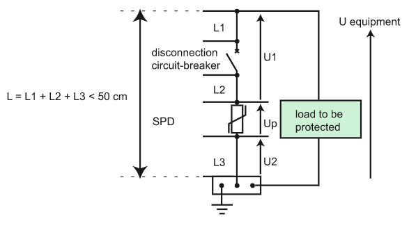
Connections of a SPD to the loads should be as short as possible in order to reduce the value of the voltage protection level (installed Up) on the terminals of the protected equipment.
The total length of SPD connections to the network and the earth terminal block should not exceed 50 cm.
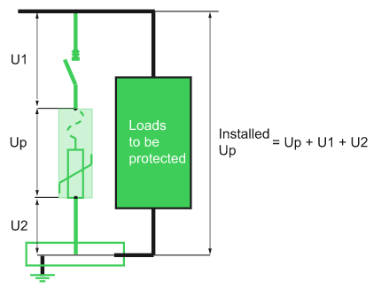
One of the essential characteristics for the protection of equipment is the maximum voltage protection level (installed Up) that the equipment can withstand at its terminals. Accordingly, a SPD should be chosen with a voltage protection level Up adapted to protection of the equipment (see Fig. J38). The total length of the connection conductors is
L = L1+L2+L3.
For high-frequency currents, the impedance per unit length of this connection is approximately 1 µH/m.
Hence, applying Lenz’s law to this connection: ΔU = L di/dt
The normalized 8/20 µs current wave, with a current amplitude of 8 kA, accordingly creates a voltage rise of 1000 V per metre of cable.
ΔU =1 x 10-6 x 8 x 103 /8 x 10-6 = 1000 V
Fig. J38 – Connections of a SPD L < 50 cm
As a result the voltage across the equipment terminals, U equipment, is:
U equipment = Up + U1 + U2
If L1+L2+L3 = 50 cm, and the wave is 8/20 µs with an amplitude of 8 kÂ, the voltage across the equipment terminals will be Up + 500 V.
Connection in plastic enclosure
Figure J39 below shows how to connect a SPD in plastic enclosure.
Fig. J39 – Example of connection in plastic enclosure
Connection in metallic enclosure
In the case of a switchgear assembly in a metallic enclosure, it may be wise to connect the SPD directly to the metallic enclosure, with the enclosure being used as a protective conductor (see Fig. J40).
This arrangement complies with standard IEC 61439-2 and the Assembly manufacturer must make sure that the characteristics of the enclosure make this use possible.
Fig. J40 – Example of connection in metallic enclosure
Conductor cross section
The recommended minimum conductor cross section takes into account:
• The normal service to be provided: Flow of the lightning current wave under a maximum voltage drop (50 cm rule).
Note: Unlike applications at 50 Hz, the phenomenon of lightning being high-frequency, the increase in the conductor cross section does not greatly reduce its high-frequency impedance.
• The conductors’ withstand to short-circuit currents: The conductor must resist a short-circuit current during the maximum protection system cutoff time.
IEC 60364 recommends at the installation incoming end a minimum cross section of:
• 4 mm2 (Cu) for connection of Type 2 SPD; • 16 mm2 (Cu) for connection of Type 1 SPD (presence of lightning protection system).
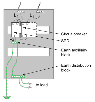
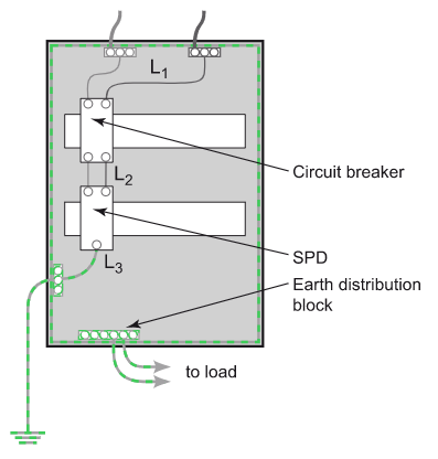
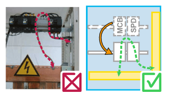
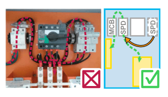
Examples of good and bad SPD installations
Example 1: Equipment installation design should be done in accordance to installation rules: cables length shall be less than 50 cm.
Example 2 : Positioning of devices should be linked to installation rules: reduce length of cables < 50 cm and keep the loop area rule of reducing impact of magnetic fields created by lightning current.
Fig. J41 – Examples of good and bad SPD installations
Cabling rules of Surge Protection Device
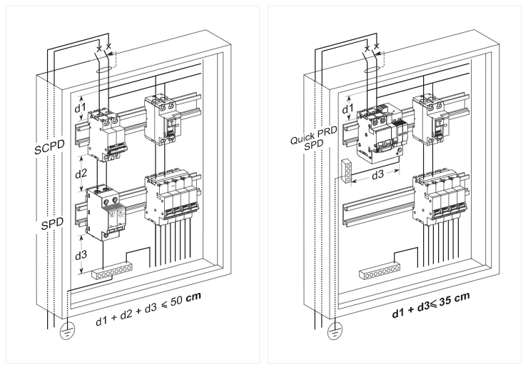
Rule 1
The first rule to comply with is that the length of the SPD connections between the network (via the external SCPD) and the earthing terminal block should not exceed 50 cm.
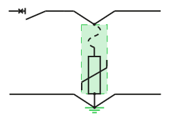
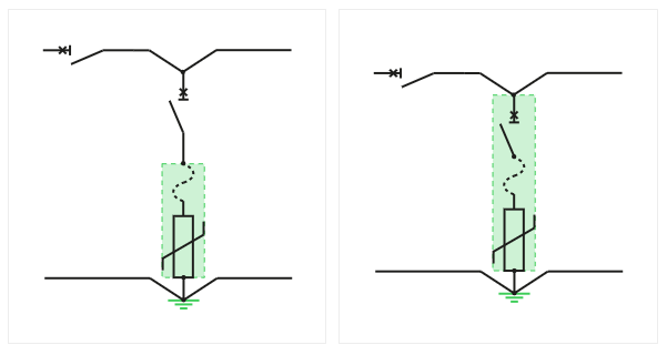
Figure J42 shows the two possibilities for connection of a SPD.
Fig. J42 – SPD with separate or integrated external SCPD
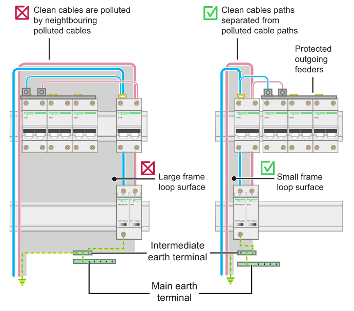
Rule 2
The conductors of protected outgoing feeders:
• should be connected to the terminals of the external SCPD or the SPD; • should be separated physically from the polluted incoming conductors.
They are located to the right of the terminals of the SPD and the SCPD (see Figure J43 ).
Fig. J43 – The connections of protected outgoing feeders are to the right of the SPD terminals
Rule 3
The incoming feeder phase, neutral and protection (PE) conductors should run one beside another in order to reduce the loop surface (see Fig. J44).
Rule 4
The incoming conductors of the SPD should be remote from the protected outgoing conductors to avoid polluting them by coupling (see Fig. J44).
Rule 5
The cables should be pinned against the metallic parts of the enclosure (if any) in order to minimize the surface of the frame loop and hence benefit from a shielding effect against EM disturbances.
In all cases, it must be checked that the frames of switchboards and enclosures are earthed via very short connections.
Finally, if shielded cables are used, big lengths should be avoided, because they reduce the efficiency of shielding (see Fig. J44).
Fig. J44 – Example of improvement of EMC by a reduction in the loop surfaces and common impedance in an electric enclosure
Published by Chuck Gougler, International Association of Electrical Inspectors (IAEI) Magazine, Electrical Fundamentals – Electrical Power Quality and Harmonic Concerns, December 29, 2015
The Problem of Harmonics
Harmonics are generated by nonlinear components in electrical systems, which distort the sine wave. Increasing usage of power electronics causes a corresponding increase in voltage distortion, or harmonics. Electrical components like variable frequency drives, uninterruptible power supplies, and inverters all introduce harmonics of differing orders into the electrical system. When harmonics are present, they can manifest themselves with short-term and long-term consequences. High harmonic distortion can cause failures or malfunctions of electrical devices. Harmonics also cause a temperature rise in the electrical network and the equipment, resulting in losses and shorter service life. Harmonic filters will help to achieve a reduction or elimination of problematic harmonics, before any damage to the electrical system or equipment can occur.
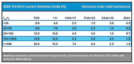
Figure 1. IEEE 519-2014 current distortion limits (%)
Electrical Power System, Harmonics Overview
In general, harmonic currents are the result of the non-linear behavior of electrical devices. The sources of harmonic currents and thus harmonic voltage in power systems are multiple and vary in size (a few KVA up to several MVA). Typically, devices with magnetic iron cores, like transformers or generators, have been a key area of harmonic concern. Today, with the demand for energy efficiency of power electronic equipment, mitigation or reduction of harmonics continues to be a priority for many commercial, industrial and industry-specific customers, such as water and wastewater treatment and oil & gas.
Numerous facilities need to meet stringent requirements in order to operate reliably and in an environmentally compliant manner. Users need to ensure the availability of the operations on a 24/7 schedule.
As the majority of electrical power supplied to the user comes from a utility source, that is, from the local utility company, most of the power problems experienced at the facility level are really derived from within the operation of the plant itself. Harmonics are commonly present within the facility power network and can present issues ranging from nuisance to catastrophic. Harmonic filtering, which can be accomplished with active or passive solutions, helps to eliminate the harmonic issues while enhancing equipment performance and the overall facility electrical power system.
IEEE-519-2014 is a widely recognized set of recommendations which includes the maximum permissible current and voltage distortion values at the point of common coupling (PCC). The distortion limit is given as a function of the system loading, i.e., the relationship between the maximum short-circuit current (ISC) and the maximum demand load current (IL) at the PCC.
When ECOsine® passive and active harmonic filters and reactors are installed in the electrical system, they will reduce the harmonics to meet the requirements of most International Standards. They unload lines and transformers upstream of the non-linear load (for example, a three-phase diode bridge rectifier) hence reducing the system overall losses and operating temperature. Additionally, the total power factor is significantly improved and will remain close to unity even at partial load.
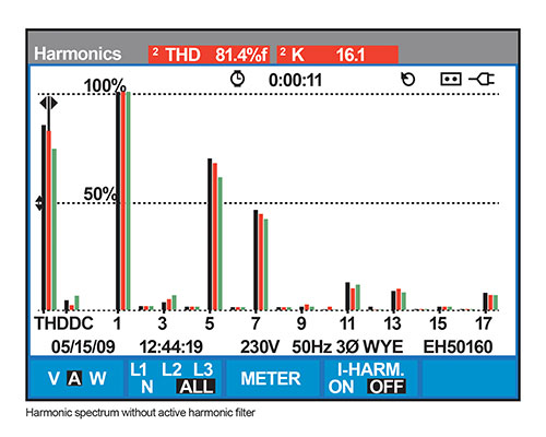
Figure 2. Harmonic spectrum without active filter
Figure 2a. Voltage and input current without active harmonic filter
Harmonics and Equipment
Frequency inverters are among the most widely used pieces of equipment for AC motor control. Such components are found in virtually every area of industry, in applications as diverse as pumps, fans, blowers, and even HVAC equipment. In the quest for ultra-compact, efficient power conversion, inverter manufacturers employ high speed semiconductor switching and pulse width modulation (PWM) techniques, which can create harmonic problems.
Arc furnaces and welders, including welding robotics, are usually very large power consuming applications. This high power, combined with a highly nonlinear voltage-current, produces substantial amounts of harmonic distortion. From a technical standpoint, arc furnaces operate in different phases (melting, air refining, refining) with different levels of harmonics. Additionally, the equipment has a combination of ignition delays and rapid voltage changes caused by random variations of the arc. This leads to an unusual harmonic spectrum with even and odd multiples of the fundamental frequency.
The electronic components within a CNC machine, for example, are particularly sensitive to “electrical imperfections” found in the power distribution system. Problems here can include malfunction of the equipment or program, along with damage to the parts and material. This can lead to missed deliveries and potential quality issues, unsatisfied customers and financial concerns for a company.
The use of variable speed drives for pumps and fans generates a harmonics content of the current in the supply that can lead to thermal overload of the electrical infrastructure and to malfunctions of sensitive equipment and components. In many water and wastewater treatment facilities, new biological stages working with bacteria are implemented. This leads to the installations of very powerful VFD-driven air compressors as bacteria need air to be able to do the job required. These VFDs are creating very high and unacceptable harmonic distortion.
Harmonics can wreak havoc on the electrical power network, causing circuit boards in PLCs to fail, tripped circuit breakers, blown fuses, overheating of motors and transformers, insulation breakdown, and reduced service life of equipment. Furthermore, production downtime/restart-time and shipment (revenue) loss, along with repair costs may result in reduced company profits.
A harmonic site survey (use of meters/analyzers) or a full engineering study may be necessary to completely determine existing harmonics (and other PQ issues), in order to provide a recommended solution to the user. In many, but not all cases, IEEE 519 (2014) guidelines are followed for the acceptable level of distortion. A complete review of the existing system, new/planned or retrofitted equipment along with any plant expansions should be considered.
Passive Harmonic Filters
One solution to mitigate harmonics would be to utilize passive harmonic filters. Such series-connected filters are typically installed “one-on-one,” in other words—one filter for each VFD. A larger passive filter can be designed to accommodate multiple drives, if required.
The most logical installation point at which to eliminate harmonics is right at the source-individual non-linear load. A passive filter provides a low impedance path for harmonic currents, required, as an example by a rectifier. This significantly reduces the amount of harmonics flowing throughout the electrical power system. The end result is the non-linear load drawing sinusoidal current from the power source/grid.
The installation of passive harmonic filters will be immediately beneficial to the electrical system, since they will help to limit the amplitudes of the current harmonics and thus reduce losses, and to operate equipment more efficiently and reliably. Additionally, they help to maximize utilization of the electric system capacity.
In a typical drive system, the total harmonic current distortion is reduced to acceptable limits and meeting IEEE 519 where applicable. Passive filters should be able to provide optimal performance at both full and lightly loaded conditions.
Passive filters can be found in two design types: 1) <5% THDi and 2) 7-10% THDi. Many times IEEE 519 is followed; however, there are applications where, say, 7 or 8% THDi improvement meet the needs of the end user. As a general “rule,” passive filters tend to be more economical than active filters, though they may not effectively mitigate a wide range of harmonic orders like active filters.
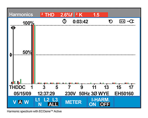
Figure 3. Harmonic spectrum with ECOsine TM Active
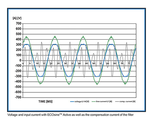
Figure 3a. Voltage and input current with ECOsine TM Active as well as the compensation current of the filter
Active Harmonic Filtering Solution
Another solution to mitigate harmonics is the use of active harmonic filters (AHF), power quality devices that permanently monitor the nonlinear load and dynamically provide precisely controlled current, helping to prevent distortion in a power network. This current has the same amplitude of the harmonic current but is injected in the opposite phase-shift, canceling out the harmonic currents in the electrical system. As a result, the current supplied by the power source will remain sinusoidal since the harmonics will negate each other, and the harmonic distortion is reduced to less than 5% THDi, meeting all standards. In addition, the AHF power electronics platform is designed to operate at levels that continuously adapt to rapid load variations. With load conditions creating harmonics up to the 50th order, active filters operate in a wide frequency range, adapting their operation to the resultant harmonic spectrum.
Active harmonic filters can also correct poor displacement power factor by compensating the system’s reactive current. The filter also balances the loads of the phases. These sophisticated devices are equipped with insulated gate bipolar transistors (IGBT) and digital signal processing (DSP) components. Generally, active harmonic filters can be installed at any point in a low-voltage AC network (parallel device), and they usually offer much more functionality than their passive filter counterparts.
Active harmonic filters combine these features with their small physical size and efficient operation, which makes them ideal choices for a wide variety of applications. Active filters can be provided for 3-wire or 4-wire connections (3-wire is the most common in North America). Current transformers deliver a signal to the filter, which can be applied to either the line or load side of the power network.
Active harmonics filters can be applied to a single or a group of nonlinear loads. Possible AHF installations include power factor correction in harmonic-rich environments in which filtering cannot be suitably achieved by the use of capacitors; where both power factor and harmonic correction are required; and where emergency power or distributed generation are present in the electrical network.
In general, active harmonic filters are available in several ratings. These ratings can include individual units for 50, 100, 200, 250 or 300 amperes. Different configurations such as open type, or various NEMA enclosure protection ratings and the ability to parallel multiple active filters, for higher current applications are typical. Installation voltages are mostly 480VAC and 600VAC. The 600VAC requirements can utilize a step-down (600/480VAC) transformer with the active harmonic filter, or use a “purpose built” active filter rated for 600/690VAC, where a transformer is not necessary. Active filters will include keypad controls and operator display communications such as RS485 and TCP/IP Ethernet, along with software for communications and monitoring through a Windows-based product.
Active filter is best utilized with 6-pulse VFDs. These VFD products are the most economical, highly common and readily available. One AHF can be used for multiple drives of any horsepower rating and any manufacturer. Drives of 18-pulse tend to have a much higher price point and, with its transformer, occupy more (valuable) space. Additionally, should an 18-pulse drive fail, it is “out of production,” whereas should an AHF fail or require service, the VFD continues to operate.
Where machinery and equipment are electronically controlled and need to meet exacting production standards, sensitive electronic components need to be protected from harmonics driven by the facility’s electrical power distribution system. The use of active harmonic filters can achieve the reliable functioning of the machinery and assure the process quality, while helping to support the financial bottom line.
Application Example with Active Filters
Power factor correction (PFC) equipment suffered from significant additional losses caused by harmonics. The installation of the AHF with a compensation current of 500 A brought the required electrical and thermal relief to the PFC, which considerably improved power quality and also made it possible for the installation of a backup generator in case of an outage. Adding the generator was previously impossible because of the prevalent harmonic content. The AHF’s unique capability to adapt to the situation of grid and load at any one time ideally helped to guarantee the continuous reliable operation of the wastewater treatment plant.
Where machinery and equipment are electronically controlled and need to meet exacting production standards, sensitive electronic components need to be protected from harmonics driven by the facility’s electrical power distribution system. The use of active harmonic filters can achieve the reliable functioning of the machinery and assure the process quality while helping to support the financial bottom line.
Final Comment
After harmonics have been identified and it’s determined a mitigation solution is required, the proper equipment selection will need to be reviewed and implemented. With the many problems associated with harmonics (equipment failure, replacement and maintenance costs, improper component or system operation, production downtime, etc.), it is suggested to keep records on these costs, to help with the ROI of any future mitigation equipment.
Published by Jose A. JARDINI1, Ricardo L. VASQUEZ-ARNEZ2, Marcos T. BASSINI1, Marco A.B. HORITA1, Gerson Y. SAIKI2 and Marcos R. CAVALHEIRO3 Polytechnic School of the University of Sao Paulo (1), Foundation for the Technological Development of the Engineering Sciences (2), CTEEP Sao Paulo State Power Transmission Company (3).
Abstract. The application of voltage source converters (VSCs) into medium- and high-power transmission is currently attracting increased attention. In view of this increased attention, this article provides the simulation results of the overvoltages produced by faults occurring in the DC line of a point-to-point VSC-based HVDC system as well as in a neighbouring AC line system. The VSC converters considered here use the MMC (modular multi-level converter) technique to generate the voltage waveform. For pole-to-ground faults occurring in the DC link of a symmetrical monopole system, significantly high overvoltages may arise on the sound pole. This condition is of concern, mainly during the planning stage of the VSC-HVDC project, as it may require the installation of surge arresters with a good performance and/or also additional insulation of the line. In addition, unless the faults occurring on the DC link are quickly removed, sustained overvoltages can threaten the normal operation of the surge arresters installed on the DC side of both sound and faulty poles. Faults and other events in the AC system (near the DC link) may lead to sustained overvoltages that should also be examined regarding the response of the surge arresters.
Streszczenie. Artykuł przedstawia rezultaty symulacji przepięć występujących w sieci DC bazującej na wykorzystaniu VSC (voltage source converters). Układ VSC wykorzystuje technikę MMC (modular multi-level converter). Rozpatrzono też wpływ sąsziadującej z siecią DC sieci AC. Analiza przepięć w sieci prądu stałego HVDC wykorzystującej technikę VSC.
Keywords: Faults, MMC technique, Overvoltages, Point-to-point system, Surge arresters, VSC-HVDC. Słowa kluczowe: przepięcia, sieci DC, zabezpieczenia przed przepięciami
Introduction
Traditionally, HVDC systems using line commutated converters (LCCs) are utilized for the transmission of bulk power over long distances. Recently, voltage sourced converters (VSCs) applied to HVDC systems also appeared as good candidates for the transmission of relatively large power (up to 1000 MW) at high voltages (up to ± 400 kV).
According to their topology, HVDC systems can be classified into various categories. However, for the purpose of this study, the configurations utilized are: a symmetrical monopole system, in which there is commonly no grounding system (Fig. 1a) and a bipolar system, with two converters in each end and where the returning path (with one pole out of service) can be accomplished through a metallic return or through the ground (Fig. 1b).
While the converters in LCC-HVDC applications use thyristors and can only control active power, the VSCHVDC configuration uses IGBTs (Insulated Gate Bipolar Transistors) as switching devices that can independently control both active and reactive power. This control is an important characteristic because in the LCC-HVDC alternative, the reactive power required by the converters, as well as the required filters, must be provided locally. Another important issue is that, due to the turn on/off characteristic of the IGBTs, the resulting voltage waveform is close to a sine wave, thereby requiring much smaller filters in the AC side.
The presence of overvoltages in DC systems using VSC-HVDC can be due to various causes, namely, faults in the system, loss of the inverter terminal, loss of load, etc. The reconnection of the rectifier, once it has been blocked, e.g., due to a fault, can also be responsible for the presence of overvoltages [1].
In underground cables, due to their physical separation and arrangement, the occurrence of pole-to-pole faults is rare. In contrast, DC overhead lines may be more prone to face such type of faults. Pole-to-pole faults are of special concern because it may cause failure of the semiconductor devices [2].
Within the VSC-HVDC technology, the Modular Multilevel Converter (MMC) has recently gained popularity due to its inherent advantages, namely: lower switching losses (i.e., lower switching frequency in each submodule), lower voltage across each switch (as only small capacitors are used in parallel with each switch), among others [3].
Recently, some MMC simulation models aimed at speeding up the computational time were proposed. For example, a detailed description of the MMC ‘average model’ and its dynamic performance under both balanced and unbalanced grid operation modes are presented in [4], [5] and [6]. A revision of the methods typically used for the protection of VSC-based HVDC systems is presented in [7]. The referred article, however, chiefly focuses on the overcurrent protection. The overvoltage protection and insulation coordination in MMC-based HVDC systems are explored in [8]. All DC lines in this reference are submarine cables, and the study conducted is focused on the insulation design of the DC line.
The effect of DC faults and their respective protection scheme in VSC-multi-terminal high voltage direct current (MTDC) transmission systems is presented in [9]. The scheme uses IGBT-based circuit breakers and its respective coordination with the converter switches (IGBTs) to block the converter during fault periods.
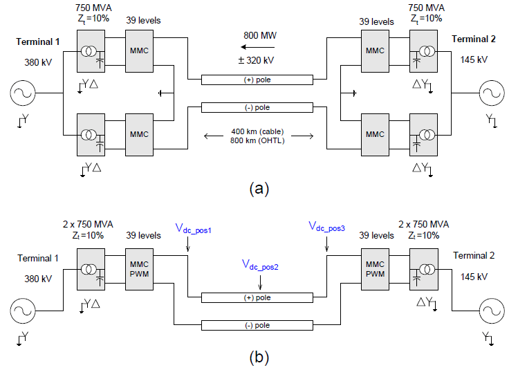
Fig.1. DC transmission configurations used: (a) symmetrical monopole and (b) bipolar system.
When a line-to-ground fault occurs in a bipolar system, the faulted pole rapidly discharges the capacitor(s) to ground. This discharge causes an imbalance of the DC link voltage between the positive and negative poles. As the voltage of the faulted line begins to fall, high currents flow from the capacitor(s) as well as from the AC grid. These high currents may damage the converters and the capacitors [10].
During faults in the DC link of a VSC-HVDC system, and also during contingencies in the AC system (involving line and/or transformers) nearby the converter stations, some overvoltages in the DC line can appear. Such overvoltages are of concern because they may have an influence on the design of the line and on the surge arresters located on the DC side of the converters.
In view of these design considerations, this article presents the magnitude of the overvoltages arising from faults occurring inside the DC link. In addition, the effect of line disconnections in another neighbouring AC grid configuration, due to inherent faults, is also presented.
Description of the DC System
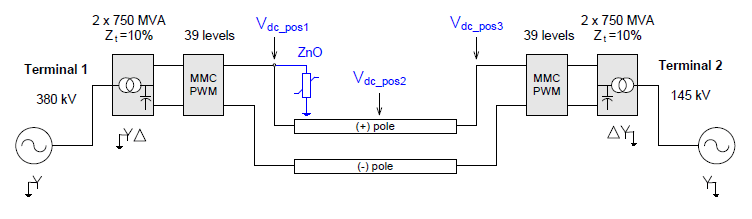
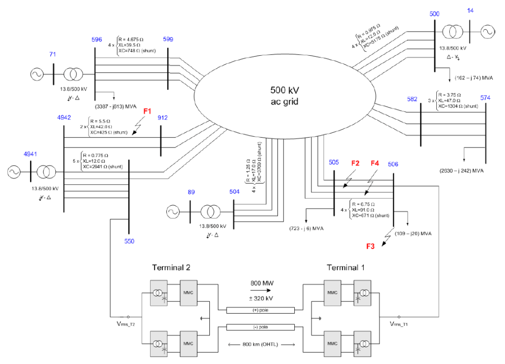
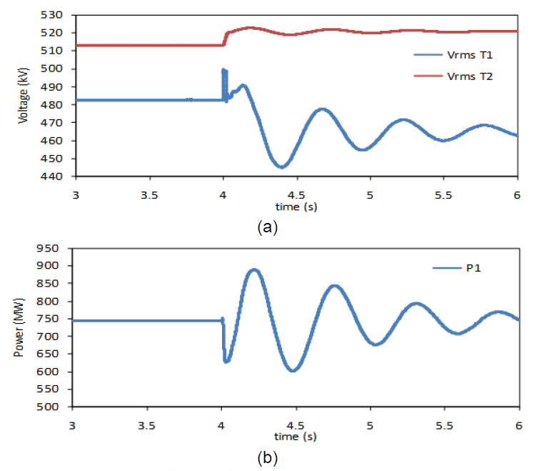
The VSC-HVDC system used here is based on the MMC technique. Additionally, the MMC converter referred to as Model 2 in [5] was used herein. A two-pole 400-km DC cable and an 800-km overhead line were independently used in the DC link of the point-to-point DC system. The nominal DC voltage and transmitted power are equal to ±320 kV and 800 MW, respectively. Both bipolar and symmetrical monopole systems, along with the AC voltages and transformer characteristics, are shown in Figs. 2(a) and 2(b), respectively. The direction of the power flow shown in these figures was set to occur from Terminal 2 to Terminal 1; however, it could also be set to flow in the opposite direction.
Fig.2. (a) Bipolar and (b) symmetrical monopolar VSC-HVDC configurations used.
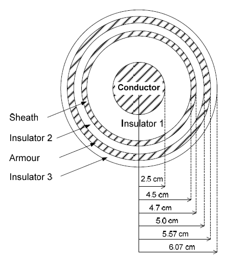
Regarding the DC link, both positive and negative cables have standard configurations, with a core (whose diameter is equal to 0.05 m), sheath and armour, as described in the Appendix section. The separation distance between both cables is 0.5 m, and the cables are buried at a depth of 1.5 m.
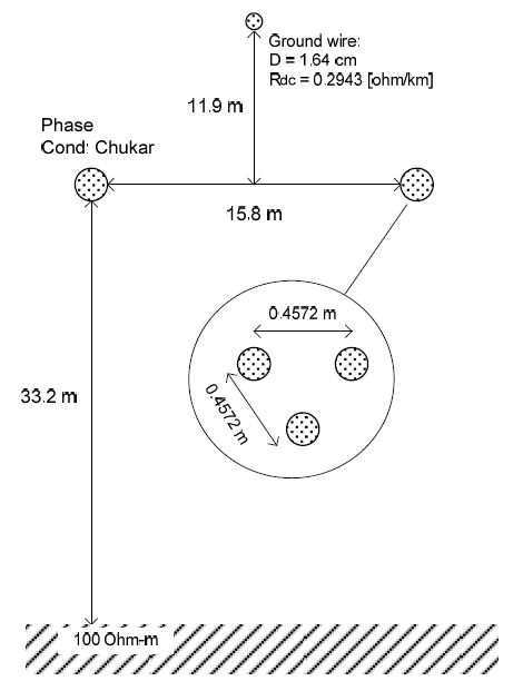
The overhead transmission line (OHTL) considered has a bundle of three ACSR conductors per pole (Chukar conductor) located at a height of 33.2 m at the tower and 14.1 m at midspan. The ground resistivity considered in both cases (i.e., cable and OHTL) was equal to 100 Ω–m. Likewise, a fault resistance equal to 0.01 Ω was considered in all the simulations.
Overvoltage Analysis
Both symmetrical monopole and bipolar VSC-HVDC systems were simulated using the PSCAD program [11] with the EMTDC as its numerical solver. For some other calculations the EMTP-RV program [12], was also used. The following faults were analysed for both the cable and the OHTL case:
a) Symmetrical Monopole System 1. Pole-to-pole fault 2. Pole-to-ground fault
b) Bipolar System 1. Pole-to-pole fault 2. Pole-to-ground fault
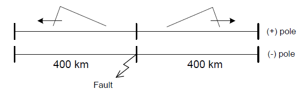
In all simulated cases, the fault (applied at t = 3.0 s and extinguished forcedly after 200 ms) was assumed to occur in the middle of the DC link (negative pole). This is because this point is one of the most critical in terms of overvoltage.
Overvoltages due to Faults in the DC Link During a fault in the DC link, two instants of overvoltage normally occur. The first one occurs at the beginning of the DC fault itself. The second one occurs at the instant when the fault is cleared. The major concern here is the overvoltages during the fault period. Note that independently of the power flow direction, both equivalent sources contribute to the fault current.
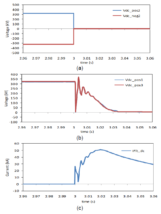
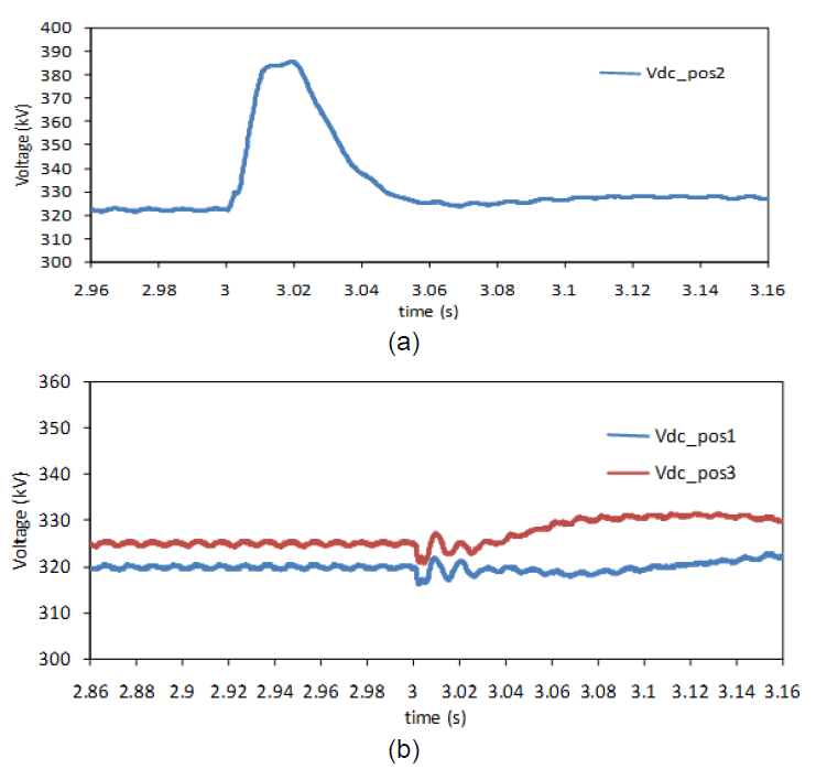
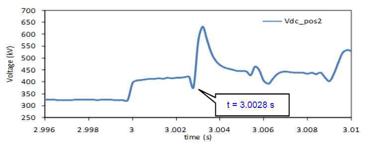
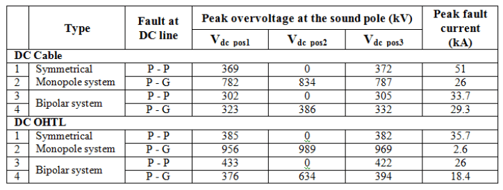
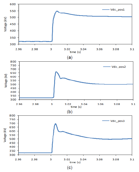
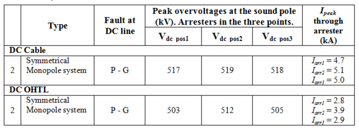
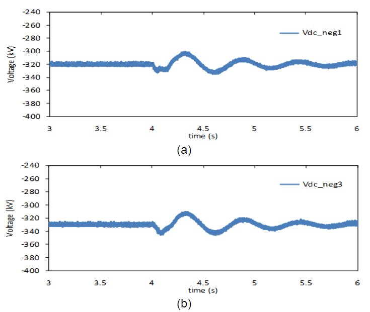
Next, the overvoltages and the behaviour of the DC link, due to the simulated faults, will be shown. The magnitude of the overvoltages at the beginning (Vdc_pos1), the middle (Vdc_pos2), and the end of the DC line (Vdc_pos3), as indicated in Fig. 2(b), will be presented. Measurements at these same points of the negative pole were also obtained. However, our main focus will be on the overvoltages created in the sound pole. A summary of all the values obtained in the study is presented in Table 1.
Fig.3. (a) DC voltage at the middle of line Vdc_pos2, Vdc_neg2, (b) voltage at Vdc_pos1, Vdc_pos3, (c) DC fault current during the pole-topole fault.
A. Use of a Cable in the DC Link
a) Symmetrical Monopole System
1. Pole-to-pole fault The voltage at the fault point in both sound and faulted pole (Vdc_pos2 & Vdc_neg2) falls to zero (Fig. 3a), whereas the peak overvoltages at Vdc_pos1 and Vdc_pos3(sound pole) are 369 kV and 372 kV, respectively (Fig. 3b). The peak of the DC current (20 ms after the fault was initiated) was approximately 51 kA (Fig. 3c).
2. Pole-to-ground fault While the voltage at the negative pole (faulted pole) drops to a very low value (close to zero), the sound pole exhibits a significantly large peak overvoltage at the middle of the line (Vdc_pos2=834 kV), as depicted in Fig. 4. The maximum overvoltages read at both the beginning and end of the sound pole (Vdc_pos1 & Vdc_pos3) were approximately 782 kV. These overvoltages are mainly due to the displacement of the (virtual) neutre in the DC link of the symmetric monopole system. Under the no fault conditions, this virtual reference is zero, with each pole operating at ±320 kV. The instant the negative pole drops nearly to zero (due to the fault) this reference is displaced; thus, resulting in higher DC voltages on the sound pole.
Fig.4. Voltage at the fault point (sound pole) for a pole-to-ground fault.
b) Bipolar System
1. Pole-to-pole fault Close results to those presented in Section A.a.1 were obtained (i.e., the voltages at the middle point Vdc_pos2and Vdc_neg2, fall to zero; whereas the values of Vdc_pos1 and Vdc_pos3 are equal to 302 kV and 305 kV, respectively). The peak fault current was equal to 33.7 kA.
2. Pole-to-ground fault The peak overvoltage at the sound pole (Vdc_pos2) was equal to 386 kV (Fig. 5a), whereas at each end of the line relatively lower voltages (Vdc_pos1 = 323 kV and Vdc_pos3 = 332 kV) were obtained (Fig. 5b). These overvoltages can present no threat to the analysed system.
Fig.5. Pole-to-ground fault in the bipolar system: (a) voltage at the middle of the line (Vdc_pos2) and (b) voltage at the receiving and sending-end of the DC cable (Vdc_pos1, Vdc_pos3).
B. OHTL as DC Link
a) Symmetrical Monopole System
1. Pole-to-pole fault The peak overvoltages read at Vdc_pos1 and Vdc_pos3were 385 kV and 382 kV, respectively. As expected, the voltage at the middle of both poles fell to zero. The value of the peak fault current was approximately 35.7 kA.
2. Pole-to-ground fault The greatest peak overvoltage at the sound pole is approximately 989 kV (Vdc_pos2 shown in Fig. 6b). In Figs.6(a) and 6(c), the values at each end of the DC line (Vdc_pos1 = 956 kV and Vdc_pos3 = 969 kV) are shown. The peak of the fault current was approximately 2.6 kA.
Fig.6. Pole-to-ground fault: (a) voltage at the receiving end of DC OHTL (Vdc_pos1), (b) in the middle of the DC line (Vdc_pos2), and (c) at the sending-end (Vdc_pos3).
b) Bipolar System
1. Pole-to-pole fault The peak overvoltages at the beginning and end of the DC line were 433 kV (Vdc_pos1) and 422 kV (Vdc_pos3), as shown in Fig. 7. The peak of the fault current was approximately 26 kA.
2. Pole-to-ground fault The peak overvoltage at the sound pole (Vdc_pos2 in Fig.8b) was approximately 634 kV. The values at both ends of the line were: Vdc_pos1 = 376 kV (Fig. 8a) and Vdc_pos3 = 394 kV (Fig. 8c). The maximum value of the fault current was equal to 18.4kA.
The overshoot inside the ellipse shown in Fig. 8(b) is also due to the contribution of the travelling waves along the DC line. This overshoot (further amplified in Fig. 9) coincides with the time taken by the travelling wave after bouncing off the converter stations at both ends (i.e., 2.8 ms after the occurrence of the fault). If in this particular conductor (OHTL) the wave propagation speed is close to the speed of light, it can be shown that the total distance travelled by this wave is equal to the length travelled on the DC line (i.e. 2×400 km in 2.8 ms). Each fast travelling wave (depicted in Fig. 10) bounces in each end of the line creating reflections which when added to the existing overvoltage it can reach values twice or more of those encountered during normal conditions.
From Table 1, it can be seen that pole-to-pole faults have the highest fault currents. Pole-to-ground faults in the case of the monopole system exhibit the highest overvoltages. Faults occurring in the DC link of the bipolar system do not create very significant overvoltages that could threaten the line’s BIL (Basic Impulse Insulation Level). The minimum BIL calculated for equipment within the substation was equal to 750 kV, whereas the BIL for the DC line resulted in 1900 kV. According to [13], the latter critical flashover voltage corresponds to a 300 kV line whose insulator chain has 18 standard disc insulators.
Fig.7. Pole-to-pole fault in the presence of the OHTL: Voltages at points Vdc_pos1 and Vdc_pos3.
Fig.8. Voltages at the fault point (pole-to-ground fault) of the sound pole.
Also, faults occurring in the dc cable resulted in relatively higher fault currents compared to the values obtained for the OHTL case (Table 1). An opposite behaviour was observed for the case of the overvoltages (i.e. the DC cable exhibited relatively lower overvoltages in relation to the OHTL).
Despite these overvoltages do not seriously threaten the line’s insulation level, it is also necessary to assess the surge arresters effectiveness for reducing such overvoltages. Such analysis is presented in the subsequent section.
Fig.9. Zoom-in of Fig. 8(b) indicating the effect of the travelling wave.
Fig.10. Travelling waves along the DC line.
Table 1. Overvoltage for the different type and fault configurations
Use of Surge Arresters Zinc Oxide (ZnO) arresters are commonly used for the protection against overvoltages in AC and DC systems. So, a ZnO arrester was placed at point Vdc_pos1 (sound pole), as depicted in Fig. 11. The rated voltage of the selected surge arrester is 240 kV (rms). Its V-I curve is presented in the Appendix. Additionally, the maximum energy that this particular arrester can absorb is 7 kJ/kV.
Fig.11. ZnO arresters placed in the sound (positive) pole.
The results obtained after the installation of a surge arrester for the symmetrical monopole configuration (pole-to-ground fault) when the DC link separately uses a cable and an OHTL, are presented in Figs. 12 and 13, respectively.
The reason for initially placing only one arrester is to better observe the effect of this overvoltage suppressor at a particular point along the line, in this case point Vdc_pos1. In practice, one arrester should be placed at each end and in each pole of the DC link. For both, cable and OHTL, the overvoltage at the protected point (Vdc_pos1) was effectively reduced to the arrester protection level (549 kV in Fig. 12a and 517 kV in Fig. 13a), but remained high in the other unprotected points.
Fig.12. (a) Overvoltage reduction due to the installation a ZnO arrester at Vdc_pos1, (b) voltage at Vdc_pos2, and (c) voltage at Vdc_pos3 (cable as DC link).
Fig.13. (a) Overvoltage reduction due to the ZnO arrester at Vdc_pos1, (b) voltage at Vdc_pos2, and (c) voltage at Vdc_pos3 (OHTL).
In Table 2, a summary of the voltages measured at Vdc_pos1, Vdc_pos2 and Vdc_pos3 is presented.
Subsequently, the surge arrester was taken to the middle of the line (positive pole). Although this option (surge arrester at middle of the line) might sound a bit uncommon, it can actually be the case of installing a “line” surge arrester on the tower itself, similar to the installation of line arresters in some ac systems.
In Table 3, the reduction of the overvoltage at point Vdc_pos2 (552 kV/320 kV=1.75 pu cable; and 532 kV/320 kV =1.66 pu OHTL) for the symmetrical monopole system, is presented. However, as expected, the voltages close to Terminals 1 and 2 (with no arresters) are still high, above 1.95 pu at both line ends. Therefore, it will be necessary to install surge arresters in more than one point.
So, surge arresters in the middle and at both ends of the DC line were placed. The three arresters effectively reduced the DC link overvoltages to the arresters protection level (Table 4). A brief analysis on the energy absorbed by the arresters is presented in Section 6.
Table 2. Overvoltage reduction at Vdc_pos1 after the installation of the ZnO surge arresters.
.
Table 3. Overvoltages at the sound pole with surge arrester installed only at middle of the (+) pole.
Energy absorbed by the arrester during the entire fault period: DC cable case: Earr2= 407.7 MJ OHTL case: Earr2= 376.4 MJ
Table 4. Voltages at the sound pole with surge arresters installed at the three points.
Energy absorbed during the entire fault period (200 ms): DC cable case: Earr1 = 156.8 MJ, Earr2= 162.8 MJ, Earr3 = 144.8 MJ. OHTL case: Earr1 = 151.5 MJ, Earr2 = 153.6 MJ, Earr3 = 138.1 MJ
Energy Absorbed by the Specific Surge Arrester(s)
During prolonged (sustained) overvoltage conditions a considerably large amount of energy might need to be absorbed by the arrester. This high energy absorbed might threaten the operation of the installed surge arrester. The energy absorbed by a single arrester located at point Vdc_pos1 (Energ_p1) is shown in Fig. 14. It can be observed that the energy absorbed keeps rising beyond the arrester’s limit (1700 kJ) which imposes a high risk of damage to the arrester.
Fig.14. Energy absorbed by only one surge arrester (Energ_p1) at Vdc_pos1 during the pole-to-ground fault (OHTL).
Now, if it is to prevent the arrester from being damaged, the DC line should be disconnected in less than 5 ms after the fault has started (at t = 3.0 s), as indicated by the segmented line of Fig. 14. The installation of three arresters (at both ends and the middle of the positive pole) also reduced significantly the energy absorbed by each arrester (see Table 4). The negative pole (line) will also require similar arresters at the same locations as those indicated for the positive pole. Closer values of the absorbed energy were obtained after the installation of surge arresters in the point-to-point system using a cable as the DC link. An alternative proposal is the installation of a resistor and chopper with sufficient energy capability at both stations.
Response of the Bipolar HVDC System Towards Faults Occurring in a Nearby AC System The point-to-point bipolar system depicted in Fig. 2(a) was embedded into a digital model of an existing AC grid, whose operating voltage is equal to 500 kV (see Fig. 15). Four AC equivalent generators feed the entire AC grid (60 Hz). All of the transmission line parameters were represented through coupled pi sections to consider their values of series impedance and shunt admittance. To conduct this analysis, the set points of the transmitted power and the voltage of the point-to-point bipolar system were kept at 400 MW/pole and +/-320 kV/pole, respectively.
Whenever an event during t(-)to t(+)in the AC system occurs (near either DC link terminal), there will be a change in the voltage angles at buses 550 and 506. The t(-)time refers to the instant just before the event, whereas t(+) refers to the instant just after the event. The angle of the AC voltage generated by the VSC remains the same from the time prior to the event occurrence. From t(-) to t(+) there will occur a change in the active power of the converters at terminals 1 and 2. The resulting (instantaneous) imbalance in these powers change the voltage in the DC line; thus, the DC voltage may increase or otherwise decrease (e.g. if the input power + losses + output power within the VSC-HVDC scheme increase; then, the DC voltage will rise, boosted by the DC link capacitor, conversely, the DC voltage will decrease). After a certain time, the controls of the converters bring both powers (P1 and P2) to the pre-event condition. The presence of this type of event in the AC system shall be simulated to check the extent these DC overvoltages are and the amount of stress that they can cause upon the DC arresters.
Fig.15. Point-to-point bipolar system within a 500 kV AC grid.
Fig.16. (a) Rms voltage at terminal T2 (sending-end) and T1 (receiving-end) and (b) AC side power (receiving-end) close to Terminal 1 for fault F4.
Fig.17. Voltages at the beginning and end of the DC link (negative pole) for fault F4.
Four types of events were applied: F1: three-phase-to-ground fault (at t = 4.0s) after which the affected line (912 – 4942) trips off at t = 4.1 s (duration of fault: 200 ms); F2: sudden permanent disconnection of two parallel lines located between buses 505-506; F3: three-phase–to-ground fault (at bus 506) through a 25 Ω reactor (fault is removed after 100 ms) and, F4: three-phase fault that causes the simultaneous permanent disconnection of three parallel lines located between buses 505-506. In all cases, low oscillations of the overvoltages were observed; however, they did not affect the DC line arresters located at the same three points of each pole. As an example, the results of the disconnection of three parallel lines between buses 505-506 (Fault F4) are presented (Figs. 16 and 17).
(Vrms_T1 = 482 kV & Vrms_T2 = 513 kV) are shown in Fig. 16(a). Notice that with the disconnection of the three lines between buses 505 and 506, the rms voltage at Terminal 1 (closer to the fault point) reaches a new operative point (around 460 kV) in relation to the pre-fault value (482 kV). This is partly due to the higher losses now present in the remaining line. In order to ensure a proper operation of the converters, this voltage drop will have to be compensated by the transformer tap changer.
The rms voltages (AC side) of Terminals 1 and 2 (Vrms_T1= 482 kV & Vrms_T2= 513 kV) are shown in Fig. 16(a). Notice that with the disconnection of the three lines between buses 505 and 506, the rms voltage at Terminal 1 (closer to the fault point) reaches a new operative point (around 460 kV) in relation to the pre-fault value (482 kV). This is partly due to the higher losses now present in the remaining line. In order to ensure a proper operation of the converters, this voltage drop will have to be compensated by the transformer tap changer.
The oscillation and subsequent damping of the AC power (in around 3.0s) at Terminal 1 (P1) is shown in Fig. 16(b). Low oscillatory patterns of the voltages in the negative pole (peak values equal to Vdc_neg1 = 340 kV and Vdc_neg3= 348 kV) were also observed for this fault (Fig. 17a and 17b, respectively). In conclusion, no significant threats over the DC link from faults occurring in a nearby ac system were found.
Conclusions
From the study conducted on the overvoltage condition due to faults regarding the operation of a point-to-point bipolar system, the following conclusions can be drawn:
– Pole-to-ground faults on the DC link of a symmetrical monopole system may give rise to high overvoltages on the DC side. This condition should be considered while developing a VSC-HVDC project.
– Sustained overvoltages due to prolonged faults on the DC link can threaten, and can even destroy, the normal operation of the surge arresters installed on the DC side. Therefore, it is recommended that the DC line be opened soon after (in this case in less than 5 ms) the occurrence of the fault.
– Overvoltages due to the faults occurring inside neighbouring AC grids may have an impact on the VSCHVDC system. Therefore, to evaluate the performance of the DC link, it is also important to determine the magnitude of such overvoltages. Regarding the analysed network, those overvoltages exhibited low non-jeopardizing values.
Appendix
All AC sources were represented as sources behind the source impedance. AC source at Terminal 1 (Fig.2): Vrms : 380 kV Rseries : 0.15335 Ω Rparallel : 100 MΩ Lparallel : 15.31 mH
All data used in this article can be willingly sent upon request.
Cable dimensions:
Fig. A1. Composition and dimensions of the cable used at the positive and negative pole.
OHTL dimensions:
Fig. A2. Dimensions of the DC overhead line.
REFERENCES
[1] Lu W. and Ooi B., DC Overvoltage Control during Loss of Converter in Multiterminal Voltage Sourced Converter Based HVDC (M-VSC-HVDC), IEEE Transactions on Power Delivery, Vol. 18, No. 3, pp. 915–920, July 2003. [2] García Alonso J. C., Mosallat F., Wachal R., Abdel-Hadi K., Half and Full Bridge MMC Fault Performance in VSC-HVDC Systems. In: CIGRE CE B4 Colloquium: HVDC and Power Electronics to Boost Network Performance, Brasilia, Oct. 2-3,pp. 1-7. [3] Lesnicar A., Marquardt R., An Innovative Modular Multi-Level Converter Topology for a Wide Power Range. IEEE Power Tech Conference, Bologna, Italy, June 2003. [4] Peralta J., Saad H., Dennetiére S., Mahseredjian J., Nguefeu S., Detailed and Averaged Models for a 401-Level MMC–HVDC System. IEEE Transactions on Power Delivery, Vol. 27, No. 3, JUL. 2012. pp. 1501-1508. DOI: 10.1109/TPWRD.2012.2188911 [5] Saad H., Dennetiere S., Mahseredjian J., Delarue P., Guillaud X., Peralta J., Nguefeu S., Modular Multilevel Converter Models for Electromagnetic Transients. IEEE Transactions on Power Delivery, Vol. PP, No. 99, 2013. DOI. 10.1109/TPWRD.2013.2285633 [6] Saeedifard M., Iravani R., Dynamic Performance of a Modular Multilevel Back-to-Back HVDC System. IEEE Transactions on Power Delivery, Vol. 25, No. 4, 2010. pp. 2903-2912. [7] Candelaria J., Park J-D., VSC-HVDC System Protection: A Review of Current Methods. In: Proc. of the IEEE/PES Power Systems Conf. and Exp. (PSCE), Phoenix (AZ), 20-23 Mar.pp.1-7. DOI: 10.1109/PSCE.2011.5772604 [8] Gu Y., Huang X., Qiu P., Hua W., Study of Overvoltage Protection and Insulation Coordination for MMC based HVDC. In: Proc. of the 2nd Int. Conf. on Computer Science and Electronics Engineering (ICCSEE 2013), Atlantis Press, Paris, pp. 2369-2372. [9] Tang L., Ooi B-T., Protection of VSC-Multi-Terminal HVDC against DC Faults. In: Proc. of the IEEE 33rd Annual Power Electronics Specialists Conf (PESC 02), Vol. 2, Cairns, Australia, Jun. 23-27, 2002. pp. 719-724. DOI: 10.1109/PSEC.2002.1022539. [10] Yang J., Zheng J., Tang G., He Z., Characteristics and Recovery Performance of VSC-HVDC DC Transmission Line Fault. In: Asia Pacific Power and Energy Engineering Conference (APPEEC), Chengdu, pp. 1–4, April 2010. [11] PSCAD/EMTDC® Program. Manitoba HVDC Research Centre, v.4.3.1.0 (x4), 2010. [12] EMTP-RV, Electromagnetic Transients Program, v. 2.6, 2013. [13] CIGRE B2/B4/C1.17, Impacts of HVDC Lines on the Economics of HVDC Projects. No. 388, Aug. 2009.
Authors: prof. dr. Jose Antonio Jardini, Polytechnic School of the University of Sao Paulo, E-mail: jose.jardini@gmail.com; dr. Ricardo Leon Vasquez-Arnez, Foundation for the Technological Development of the Engineering Sciences (FDTE), E-mail: ricardoleon00@yahoo.co.uk; msc. Marcos T. Bassini, Polytechnic School of the University of Sao Paulo, E-mail: mtbassini@gmail.com; msc. Marco Antonio Barbosa Horita, Polytechnic School of the University of Sao Paulo, E-mail: marcoabh@gmail.com; msc. Gerson Yukio Saiki, Foundation for the Technological Development of the Engineering Sciences (FDTE), E-mail: gsaiki@fdte.org.br; Marcos Rodolfo Cavalheiro, CTEEP Sao Paulo State Power Transmission Company, E-mail: mcavalheiro@cteep.com.br. The correspondence address is: e-mail: ricardoleon00@yahoo.co.uk
Source & Publisher Item Identifier: PRZEGLĄD ELEKTROTECHNICZNY, ISSN 0033-2097, R. 91 NR 8/2015. doi:10.15199/48.2015.08.26
Published by Clive Kimblin, International Association of Electrical Inspectors (IAEI) Magazine, Electrical Safety – Circuit Overcurrent Protection, March 16, 2002
Overcurrent devices protect the circuit conductors and conductor insulation from overheating. They also limit the damage associated with overheating and faults in downstream equipment. Fuses performed this function during the first days of electrical distribution, but circuit breakers of ever increasing sophistication have been available since the early 1900s. This paper focuses on circuit breakers and describes the wide variety of available devices. The emphasis is on low-voltage residential, industrial and commercial applications where the circuit voltages range from 120 volts through 600 volts. This is the area that is commonly encountered by electrical inspectors. The residential area is principally served by single and two-pole molded-case circuit breakers while the industrial and commercial world is principally served by higher current single and two-pole breakers and by three-pole molded-case circuit breakers. The paper also discusses low-voltage power circuit breakers and medium-voltage vacuum circuit breakers. The paper concludes with a brief description of the protective functions available with electronic trip devices. These include trip units with adjustable settings and with integrated ground-fault detection, and circuit breakers with communication capabilities to remote monitors including via the Internet. Electronics also bring additional safety features to the industrial and commercial area such as zone-interlocking between molded-case circuit breakers and power breakers, and additional safety features to the residential area such as ground-fault circuit interrupters and arc-fault circuit interrupters combined with residential circuit breakers.
Introduction
Figure 1. An interior view of a typical single-pole miniature circuit breaker
Since the subject of this paper is overcurrent protection, the paper first addresses the meanings of the words “overload” and “overcurrent.” There is also a brief description of the method used for circuit interruption; namely, arc extinction within the circuit breaker. The paper then focuses on residential circuit breakers, sometimes referred to as miniature circuit breakers, followed by a description of industrial/commercial molded-case circuit breakers. This includes a discussion of molded-case circuit breaker maintenance. There is a subsequent description of low-voltage power circuit breakers, and of medium-voltage vacuum circuit breakers. The paper concludes with a discussion of the role of electronics in circuit protection, including reference to the latest developments in communications capability via the Internet, and mention of new safety devices such as arc-fault circuit interrupters.
Overcurrent Protection and Arc Interruption
Figure 2. The typical continuous current range is 15 A – 225 A and the typical short-circuit-current ratings are 10 k -42 k A. Representative residential circuit breakers appear
All circuit breakers have the primary function of protecting the circuit conductors by detecting and interrupting overcurrents. Such faults can involve relatively modest currents such as overloads, or the large short-circuit overcurrents associated with faults between conductors. The definitions of terms from the National Electrical Code1 are as follows:
Overcurrent. Any current in excess of the rated current of equipment or the ampacity of a conductor. It may result from overload, short circuit, or ground fault.
Overload. Operation of equipment in excess of normal, full-load rating, or of a conductor in excess of rated ampacity that, when it persists for a sufficient length of time, would cause damage or dangerous overheating. A fault, such as a short circuit or ground fault, is not an overload.
The IEC definition of overload2 provides additional clarity:
Overload. Operating conditions in an electrically undamaged circuit, which cause an overcurrent.
Figure 3. An outline of a three-phase molded-case circuit breaker
All circuit breakers interrupt current by separating current-carrying contacts. An electrical arc is established at the last point of contact and, in an alternating-current circuit, this arc conducts the circuit current until the current wave passes through zero. The arc plasma is comprised of ionized ambient material, for example, air and metal vapor, and has temperatures exceeding 5000 degrees C. The arc continuously receives power from the circuit as measured by the arc voltage multiplied by the arc current, and continually loses power due to thermal-conduction, radiation, and convection. At current zero, the power input is removed, the contact-polarity is reversed, and there is a race between the factors that tend to cool the arc plasma and the factors such as the circuit voltage that tend to cause arc reignition. It must be noted that controlled arcs, within overcurrent devices, perform an extremely useful function. If arc creation did not occur during contact separation, the circuit current would collapse to zero instantaneously causing high overvoltages in inductive elements such as motors and transformers. Circuit breakers are designed to interrupt short-circuit fault currents ranging from 10 kA in residential branch circuits through 200 kA in industrial and commercial circuits, and much of this design involves control of the associated high current arc within the circuit breaker, with arc extinction and circuit interruption at current zero.
Residential Molded-Case Circuit Breakers
Residential overcurrent protective devices such as miniature circuit breakers are designed to protect circuit conductors by opening automatically before conductor damage is caused by excessive I-squared-t ohmic heating. Protection is achieved by having the response curve of the breaker, the time-current curve, lower than the corresponding thermal damage characteristics for the conductor. In common with most circuit breakers, a charged spring causes the contacts to separate when the mechanism is tripped.
Figure 4. A range of industrial/commercial molded-case circuit breakers
Residential circuit breakers are thermal-magnetic devices. For low-current overloads, the breaker trips due to the heating of an internal bimetal. For short-circuit-fault currents, the circuit breaker must respond more rapidly, and the breaker trips “instantaneously” due to internal magnetic forces. An interior view of a typical single-pole miniature circuit breaker appears in figure 1.
Thermal trip action is achieved through the use of a bimetal heated by the load current. A bimetal consists of two strips of metal bonded together. Each strip has a different thermal rate of heat expansion. Heating of the bimetal due to overload current will cause the bimetal to bend or deflect. The metal having the greater rate of expansion will be on the outside of the bend curve. On a sustained overload, the deflecting bimetal will physically push the trip bar, causing the operating mechanism to unlatch. The time needed for the bimetal to bend, to unlatch the mechanism and to trip the circuit breaker, varies inversely with the current.
Magnetic trip action is achieved through the magnetic forces associated with high short-circuit-fault currents. An armature moves in response to these forces, unlatches the mechanism and causes the breaker to trip.
Residential circuit breakers are qualified to UL 4893 and are a general category4 that includes single and two-pole circuit breakers with continuous currents of 225 A or less, and with voltage ratings of 120 V, 127 V, 120/240 V. These breakers may also be used in industrial/commercial applications. The typical continuous current range is 15 A–225 A and the typical short-circuit-current ratings are 10 kA–42 k A. Representative residential circuit breakers appear in figure 2.
An outline of a three-phase molded-case circuit breaker is shown in figure 3. The function of the molded-case (frame) is to provide an insulated housing to mount all of the components. The operating mechanism opens and closes the three sets of contacts simultaneously (common-trip), and is driven by a spring-loaded mechanism. The springs are charged by moving the handle first to the “off” position and then to the “on” position. The motion of a trip-bar trips the mechanism and, in a thermal-magnetic breaker, this motion is again initiated either by a bimetal or by a magnetic trip. In figure 3, each pole contains an electromagnet whose winding is in series with the load current. When a short-circuit fault occurs, the current passing through the circuit conductor causes the magnetic-field-strength of the electromagnet in the breaker to rapidly increase and attract the armature. As the armature is attracted to the electromagnet, the armature rotates the trip bar causing the mechanism to unlatch and the circuit breaker to trip.
In each pole there is typically one stationary and one moveable contact. On tripping, an arc is drawn between the separating contacts, and this arc is then controlled by the arc extinguishers (arc chutes) with interruption at current zero. Industrial/commercial molded-case circuit breakers can be equipped with many features. The larger frame sizes are frequently equipped with electronic trip units to permit greater control of the time-current tripping characteristics. This permits, for example, precise coordination between overcurrent devices connected in series. Electronic trip units can also be designed to detect ground faults and earth leakage currents, and units equipped with communication capabilities can send circuit breaker status information, and additional information such as circuit energy consumption, to distant monitors or remote data acquisition systems.
All three-pole circuit breakers, and one and two-pole breakers with ampere ratings over 225 A and voltage ratings above 240 V, are usually categorized4 as industrial/commercial circuit breakers. These circuit breakers are also qualified to UL 4893. An important sub-category is the current limiting circuit breaker that is designed to cause an extremely rapid build-up of arc voltage. These breakers4, when operating within their current-limiting range, limit the let-through I-squared-t to a value less than the I-squared-t of a half-cycle wave of the symmetrical prospective short-circuit-fault current.
Typical industrial/commercial circuit breakers frame sizes range from 125 A– 3000 A, typical voltages range from 120 V – 600 V and typical short-circuit-current ratings range from 10 kA – 200 kA. Figure 4 shows a range of industrial/commercial molded-case circuit breakers.
Three major features of circuit breakers are 1) they are common trip and consequently isolate all phases of the circuit, 2) they can be provided with electronic enhancements, and 3) they can be reset multiple times without replacement. Since molded-case circuit breakers are not intended to be opened for examination and maintenance, the life and maintenance of these re-settable circuit breakers will be addressed.
All overcurrent protective devices need to be maintained. They need to be housed in an appropriate environment, and their condition needs to be checked periodically. In particular, when an overcurrent protective device operates automatically, good practice dictates that the source of the overcurrent should be located, and that the condition of the overcurrent protective device should be checked prior to circuit re-energization. The specific requirements for molded-case circuit breaker maintenance and the associated considerations for circuit breaker life are as follows.
Figure 5. Representative low-voltage power circuit breaker frames
When appropriately maintained, molded-case circuit breakers provide reliable protection for many years. The exact lifetime of the breaker, however, is determined by the circuit breaker’s operational duty and by its environment. With respect to operational duty, for most circuits there will be occasional overload conditions or low-current fault conditions. Here the operating life will be tens of years. In other circuits, there will be occasional high short-circuit-current faults. This will reduce the circuit breaker’s operating life and may necessitate circuit breaker replacement. Here it is noted that molded-case circuit breakers, when evaluated according to the standard UL 489 “Molded-case Circuit Breakers, Molded-case Switches, and Circuit Breaker Enclosures”3, are subjected to bolted fault conditions at maximum short-circuit-current rating in two separate tests. Thus circuit breakers have a finite interrupting capability, and breakers that experience multiple high short-circuit-current faults should receive a thorough inspection with replacement if necessary.
With respect to environmental effects, circuit breakers are sometimes exposed to high ambient temperatures, to high humidity and to other ambient conditions that are hostile to long performance. For example, industries may have corrosive environments or could be associated with dusty environments that could affect operating parts.
It is not intended that molded-case circuit breakers be disassembled for inspection. However, the condition of molded-case circuit breakers can be evaluated by using NEMA AB4 “Guidelines for Inspection and Preventive Maintenance of Molded-case Circuit Breakers used in Industrial and Commercial Applications.”5
This document should be referenced during periodic maintenance or during specific inspection following a high short-circuit-current fault. The document is intended to ensure that molded-case circuit breakers are well maintained, and provides guidelines for circuit breaker replacement.
NEMA AB4 is divided into separate sections dealing with:
• Inspection Procedures • Preventive Maintenance • Test Procedures • Accessory Device Test Procedures
The section dealing with Inspection Procedures describes thermal and visual checks of the circuit breaker’s condition. Overheating of the circuit breaker would necessitate further investigation, and cracks in the molded case would certainly necessitate circuit breaker replacement.
The section dealing with Preventive Maintenance insures that the circuit breaker’s life is not compromised by external conditions. The objectives are that the circuit breaker operates in a clean environment, that the connections at the terminals are torqued properly and are in good condition, and that the circuit breaker is correctly wired.
Figure 6. As indicated in the cut-away view of figure 6, two contacts oppose each other within a vacuum envelope
The section dealing with Test Procedures deals with non-destructive tests that can be used to verify specific operating characteristics of molded-case circuit breakers: Mechanical Operation Test, Insulation Resistance Test, Individual Pole Resistance Test (millivolt drop test), Inverse Time Overcurrent Test, Instantaneous Overcurrent Trip Test, and Rated Hold-In Test. Non- compliance of one or more of these tests could lead to circuit breaker replacement.
In summary, following an automatic overcurrent interruption, the condition of any protective device should be checked prior to circuit re-energization. For molded-case circuit breakers, the condition of the circuit breaker is assessed without opening or disassembling the breaker. For tripping events caused by overloads and low-current faults, evaluation usually takes the form of visual inspection and mechanical operation. However, circuit breakers that have experienced multiple high short-circuit-current faults, as evidenced by conditions at the source of the faults, should receive a thorough inspection per the guidelines of NEMA AB4. This document should also be used for recommended, periodic, preventive maintenance.
Power Circuit Breakers
As a broad generalization, molded-case circuit breakers are applied downstream from low-voltage power circuit breakers, and are designed to be connected to circuits comprised of insulated wires and insulated cables rather than bare bus bars. As previously mentioned, a primary function of these molded-case circuit breakers is to protect the conductor and the conductor insulation, and the tests in the UL 489 standard consequently incorporate wire in the testing procedures. By contrast, low-voltage power circuit breakers are typically connected by buswork within switchgear. The ANSI standards6 therefore incorporate bus bar conductors into the testing procedures. Another general distinction is that the upstream low-voltage power circuit breakers typically have a “short-time-rating” current capability that permits these circuit breakers to remain closed during fault-clearance by a downstream circuit breaker. This optimizes the availability of power to the parallel downstream circuits protected by the single upstream breaker.
For power circuit breakers, typical continuous current ranges are 800 A–5000 A, typical voltage ranges are 240 V–600 V and typical short-circuit-current ranges are 40 kA–100 kA. Figure 5 shows representative low-voltage power circuit breaker frames.
The main differences between low-voltage power circuit breakers and molded-case circuit breakers are as follows7:
Low-voltage power circuit breakers are evaluated for “short-time duty cycle” tests. This test demonstrates that the low-voltage power circuit breaker can remain closed (or “hold-in”) for at least 0.5 seconds while the downstream (feeder) breaker has the opportunity to clear the fault. Further, the main circuit breaker must continue to “hold in” in the event that the downstream breaker subsequently re-closes, the fault is still present, and the downstream breaker has to re-open in order to isolate the fault.
Low-voltage power circuit breakers are also evaluated for a “short-circuit current duty cycle” test. The test demonstrates that a main low-voltage power circuit breaker can remain closed for at least 0.5 seconds while a downstream (feeder) circuit breaker has the opportunity to clear the fault, but if the fault current persists, the main circuit breaker must open and interrupt. Again, the continued closure of the main circuit breaker maintains power continuity to the unaffected downstream circuits and optimizes coordination.
Figure 7. Typical medium-voltage circuit breakers using vacuum interrupter technology
Low-voltage power circuit breakers are equipped with stored energy mechanisms. This permits sequences of contact opening, contact re-closure, and contact re-opening, which can be activated either remotely or locally.
Low-voltage power circuit breakers can be serviced and maintained. This is important for applications where circuit breaker replacement is inconvenient and extended life is important. Further, these breakers are used primarily in draw-out switchgear. Thus, low voltage power circuit breakers typically are designed with rear-mounted primary disconnect contacts to permit the circuit breaker to be connected to and disconnected from the primary circuit stabs in the switchgear.
Low-voltage power circuit breakers receive single pole tests at 87 percent of rated interruption current at line-to-line voltage. This reflects the possibility of high single-pole fault currents in the upstream circuit location. In particular, such circuit breakers are suitable for corner-grounded delta-connected transformer applications.
ULs 1066 and UL 489 both cover similar continuous current ranges. However, since low-voltage power circuit breakers are applied upstream from molded-case circuit breakers, and since they typically supply several parallel downstream circuits, low-voltage power circuit breakers are usually high-continuous-current devices.
Low-voltage power circuit breakers are all rated to carry 100 percent of their rated continuous current within the switchgear. For molded-case circuit breakers in enclosures, the maximum circuit current is 80 percent of rated current, although 100 percent rated circuit breakers are available.
Medium-Voltage Vacuum Circuit Breakers
In low-voltage circuits, the magnitude of the circuit fault current is limited by the voltage developed across the arc drawn between the separating contacts. This arc voltage of tens or possibly hundreds of volts can approach the circuit voltage with resulting current limitation. However, in medium voltage circuits of 2.3 kV through 38 kV, the arc voltage is small compared to the circuit voltage, and the circuit breaker experiences the full available fault current.
The technology of choice for medium-voltage overcurrent protection is vacuum. Here each pole of the 3-phase circuit breaker contains a vacuum interrupter of deceptively simple construction. As indicated in the cut-away view of figure 6, two contacts oppose each other within a vacuum envelope.
During overcurrent conditions, the current-carrying contacts are separated and an arc is established in the metal-vapor evaporated from local hot spots that develop on the contacts. The circuit current is conducted through the arc plasma formed from the ionized metal vapor. During current flow there is continual evaporation from the local hot spots on the contacts with continual condensation of the ionized metal vapor on the broader contact surfaces and on the vapor condensation shield. At current zero the power input to the arc is removed and the evaporation ceases. However, the loss of inter-contact ionized vapor continues and a vacuum condition is re-established. Further, the contact polarity reverses. This results in a rapid change of the inter-contact region from an electrical conductor to an insulator within microseconds of current zero.
The keys to vacuum interrupter design are the selection and creation of the contact material, the design of the contacts for arc control, and the creation of a vacuum envelope that maintains a high vacuum condition for tens of years. Figure 7 shows typical medium-voltage circuit breakers using vacuum interrupter technology.
Electronics in Circuit Protection
Thermal-magnetic trip units are economic and compact. They have been used effectively and efficiently for many years. Their function can also be performed by electronic trip units. The first use of electronics, in the 1960s, was associated with protective relays for medium voltage circuit breakers. Since the early 1970s electronic trip units have been increasingly applied to power circuit breakers and the larger frame sizes of industrial/commercial molded-case circuit breakers. The present thrust is to make electronic trip units available down to frame sizes of 250 A and below. The advantage of electronic trip units is that time-current curves can be readily adjusted; both for phase current settings and for the settings of integrated ground fault units4. This flexibility permits coordination between series connected overcurrent protective devices such that, under fault conditions, only the device immediately upstream from the fault will clear the circuit. A further advantage is that the trip characteristic is independent of ambient temperature.
The electronic circuits on circuit breakers may also incorporate communications capability. At first this was limited to applications such as zone-selective-interlocking. Here an upstream power circuit breaker is set to trip with no intentional delay, but a trip-restraint-signal from a downstream circuit breaker can cause the power breaker to remain closed for settings up to 0.5 seconds, the maximum short-time duration. When a fault occurs on the load side of a selectively coordinated downstream circuit breaker, this downstream breaker communicates that a fault has been detected and the upstream power breaker then permits the downstream breaker to interrupt the fault. However, if the fault occurs between the power circuit breaker and the downstream circuit breaker, no restraint signal is received from the downstream circuit breaker, and the power circuit breaker will clear the fault without any intentional delay.
Communications capability is now used8 to transmit data to remote monitors or data acquisition systems. The initial information was limited to open/close status. This was followed by information on “cause-of-trip” and most recently by electrical metering data and by complete power quality data. In fact, it is now possible, from a remote location, to monitor and diagnose the electrical situation in a total industrial plant based on information communicated via the Internet.
Electronic advances have also increased the safety protection of residential circuit breakers. Ground-fault circuit interrupters have been available for many years9 and these circuit breakers, in addition to protecting the branch circuit wiring against overcurrents, provide personnel protection against electrical shock in cords and equipment connected to the outlets. Arc-fault circuit interrupters10 have been introduced during the past five years. These devices recognize the specific characteristics of arcing faults, and then interrupt the circuit. When combined with residential circuit breakers and located at the origin of the branch circuit, these AFCIs mitigate the effects of electrical arcs in the branch circuit wiring and in the cords connected to the outlets. Residential circuit breakers with combined GFCI/AFCI protection are also available.
Summary
Circuit breakers protect the circuit conductors against overcurrent. This is accomplished by first detecting the overcurrent and then interrupting the overcurrent with subsequent isolation. Thermal-magnetic trip units or electronic trip units detect the overcurrent. Interruption and isolation is accomplished by drawing an arc between separating contacts, with subsequent arc extinction. Circuit breakers can be broadly classified as low-voltage residential molded-case circuit breakers, low- voltage industrial/commercial molded-case circuit breakers, low-voltage power circuit breakers and medium-voltage circuit breakers. An overall electrical distribution system can be expected to incorporate all classes of circuit breaker. Electronics has increased the sophistication of trip units, including communications capability, and has permitted additional safety features such as shock-protection through GFCIs and enhanced fire protection through AFCIs.
References
1.NFPA 70,National Electrical Code2002, Article 100, (National Fire Protection Association, Quincy, MA, 2002), p. 70-37. 2 “International Standard for Low Voltage Switchgear and Controlgear, Part 1: General Rules,” International ElectroTechnical Commission Standard IEC 60947-1, Third Edition, 1999-02. 3 “UL Standard for Safety for Molded-case Circuit Breakers, Molded-case Switches, and Circuit Breaker Enclosures,” UL-489, (Underwriters Laboratories, Ninth Edition), October 31, 1996. 4 “Molded-case Circuit Breakers and their Application,” NEMA AB3-2001, (National Electrical Manufacturers Association). 5 “Guidelines for Inspection and Preventive Maintenance of Molded-case Circuit Breakers used in Industrial and Commercial Applications,” NEMA AB4-2000, (National Electrical Manufacturers Association). Recognized as an American National Standard (ANSI). 6 “UL Standard for Safety for Low-Voltage AC and DC Power Breakers Used in Enclosures,” UL 1066, (Underwriters Laboratories, Third Edition), May 30, 1997. Recognized as an American National Standard (ANSI). 7 Kimblin, C.W. and Long, R.W., “Comparing Test Requirements for Low Voltage Circuit Breakers,” IEEE Industry Applications Magazine, January/February 2000, p. 45-52. 8 Engel, J.C., Murphy, W.D., and Oravetz, D.M., “Remote Monitoring of Circuit Breakers,” Conference Record of the 1999 IEEE Industry Applications Conference, Phoenix, Arizona, October 1999, p.2344-2347 9 “Overcurrents and Undercurrents – All about GFCIs and AFCIs,” Earl W. Roberts, (Reptec, Mystic, CT), 2000. 10 Kimblin, C.W., Engel, J.C., and Clarey, R.J., “Arc-Fault Circuit Interrupters, The New Residential Electrical-Safety Technology,” IAEI News, Volume 72, Number 4, July/August 2000, p. 26-31.
Author: Clive W. Kimblin is the manager, Applications & Standards for the Electrical Distribution Products Operations of Cutler-Hammer, He obtained a B.Sc (Physerations of Cutler-Hammer. He obtained a B.Sc (Physics) and Ph.D. (Electrical Engineering) from Liverpool University, England and an MSIE (Engineering Management) from the University of Pittsburgh. Prior to his current position, he worked at the Westinghouse Research and Development Center in Pittsburgh and at Holec/Begemann in The Netherlands. He is active within NEMA and is an IEEE Fellow.
Published by Electrical Installation Wiki, Chapter J. Overvoltage protection – Design of the electrical installation protection system
To protect an electrical installation in a building, simple rules apply for the choice of
• SPD(s); • its protection system.
For a power distribution system, the main characteristics used to define the lightning protection system and select a SPD to protect an electrical installation in a building are:
• SPD – quantity of SPD – type – level of exposure to define the SPD’s maximum discharge current Imax.
• Short circuit protection device – maximum discharge current Imax; – short-circuit current Isc at the point of installation.
The logic diagram in the Figure J20 below illustrates this design rule.
Fig. J20 – Logic diagram for selection of a protection system
The other characteristics for selection of a SPD are predefined for an electrical installation.
• number of poles in SPD; • voltage protection level Up; • operating voltage Uc.
This sub-section Design of the electrical installation protection system describes in greater detail the criteria for selection of the protection system according to the characteristics of the installation, the equipment to be protected and the environment.
Elements of the protection system
A SPD must always be installed at the origin of the electrical installation.
Location and type of SPD
The type of SPD to be installed at the origin of the installation depends on whether or not a lightning protection system is present. If the building is fitted with a lightning protection system (as per IEC 62305), a Type 1 SPD should be installed.
For SPD installed at the incoming end of the installation, the IEC 60364 installation standards lay down minimum values for the following 2 characteristics:
• Nominal discharge current In = 5 kA (8/20) µs; • Voltage protection level Up (at In) < 2.5 kV.
The number of additional SPDs to be installed is determined by:
• the size of the site and the difficulty of installing bonding conductors. On large sites, it is essential to install a SPD at the incoming end of each subdistribution enclosure.
• the distance separating sensitive loads to be protected from the incoming end protection device. When the loads are located more than 10 meters away from the incoming-end protection device, it is necessary to provide for additional fine protection as close as possible to sensitive loads. The phenomena of wave reflection is increasing from 10 meters see Propagation of a lightning wave
• the risk of exposure. In the case of a very exposed site, the incoming-end SPD cannot ensure both a high flow of lightning current and a sufficiently low voltage protection level. In particular, a Type 1 SPD is generally accompanied by a Type 2 SPD.
The table in Figure J21 below shows the quantity and type of SPD to be set up on the basis of the two factors defined above.
Fig. J21 – The 4 cases of SPD implementation
Protection distributed levels
Several protection levels of SPD allows the energy to be distributed among several SPDs, as shown in Figure J22 in which the three types of SPD are provided for:
• Type 1: when the building is fitted with a lightning protection system and located at the incoming end of the installation, it absorbs a very large quantity of energy; • Type 2: absorbs residual overvoltages; • Type 3: provides “fine” protection if necessary for the most sensitive equipment located very close to the loads.
Fig. J22 – Fine protection architecture
Note: The Type 1 and 2 SPD can be combined in a single SPD
Common characteristics of SPDs according to the installation characteristics
Operating voltage Uc
Depending on the system earthing arrangement, the maximum continuous operating voltage Uc of SPD must be equal to or greater than the values shown in the table in Figure J23.
Fig. J23 – Stipulated minimum value of Uc for SPDs depending on the system earthing arrangement (based on Table 534.2 of the IEC 60364-5-53 standard)
N/A: not applicable U: line-to-line voltage of the low-voltage system
a.^1,2 these values are related to worst-case fault conditions, therefore the tolerance of 10 % is not taken into account.
The most common values of Uc chosen according to the system earthing arrangement. TT, TN: 260, 320, 340, 350 V IT: 440, 460 V
Voltage protection level Up (at In)
The IEC 60364-4-44 standard helps with the choice of the protection level Up for the SPD in function of the loads to be protected. The table of Figure J24 indicates the impulse withstand capability of each kind of equipment.
Fig. J24 – Required rated impulse voltage of equipment Uw (table 443.2 of IEC 60364-4-44)
a.^ According to IEC 60038:2009. b.^ This rated impulse voltage is applied between live conductors and PE. c.^1,2 In Canada and USA, for voltages to earth higher than 300 V, the rated impulse voltage corresponding to the next highest voltage in this column applies. d.^ For IT systems operations at 220-240 V, the 230/400 row shall be used, due to the voltage to earth at the earth fault on one line.
Fig. J25 – Overvoltage category of equipment
The “installed” Up performance should be compared with the impulse withstand capability of the loads.
SPD has a voltage protection level Up that is intrinsic, i.e. defined and tested independently of its installation. In practice, for the choice of Up performance of a SPD, a safety margin must be taken to allow for the overvoltages inherent in the installation of the SPD (see Figure J26 and Connection of Surge Protection Device).
Fig. J26 – Installed Up
The “installed” voltage protection level Up generally adopted to protect sensitive equipment in 230/400 V electrical installations is 2.5 kV (overvoltage category II, see Fig. J27).
• Depending on the system earthing arrangement, it is necessary to provide for a SPD architecture ensuring protection in common mode (CM) and differential mode (DM).
Fig. J27 – Protection need according to the system earthing arrangement
a.^ The protection between phase and neutral can either be incorporated in the SPD placed at the origin of the installation, or be remoted close to the equipment to be protected b.^ If neutral distributed
Note:
•Common-mode overvoltage A basic form of protection is to install a SPD in common mode between phases and the PE (or PEN) conductor, whatever the type of system earthing arrangement used.
•Differential-mode overvoltage In the TT and TN-S systems, earthing of the neutral results in an asymmetry due to earth impedances which leads to the appearance of differential-mode voltages, even though the overvoltage induced by a lightning stroke is common-mode.
2P, 3P and 4P SPDs (see Fig. J28)
• These are adapted to the IT, TN-C, TN-C-S systems. • They provide protection merely against common-mode overvoltages.
Fig. J28 – 1P, 2P, 3P, 4P SPDs
1P + N, 3P + N SPDs (see Fig. J29)
• These are adapted to the TT and TN-S systems. • They provide protection against common-mode and differential-mode overvoltages
Fig. J29 – 1P + N, 3P + N SPDs
Selection of a Type 1 SPD
Impulse current Iimp
• Where there are no national regulations or specific regulations for the type of building to be protected: the impulse current Iimp shall be at least 12.5 kA (10/350 µs wave) per branch in accordance with IEC 60364-5-534.
• Where regulations exist: standard IEC 62305-2 defines 4 levels: I, II, III and IV
The table in Figure J31 shows the different levels of Iimp in the regulatory case.
Fig. J30 – Basic example of balanced Iimp current distribution in 3 phase system
Fig. J31 – Table of Iimp values according to the building’s voltage protection level (based on IEC/EN 62305-2)
Autoextinguish follow current Ifi
This characteristic is applicable only for SPDs with spark gap technology. The autoextinguish follow current Ifi must always be greater than the prospective short-circuit current Isc at the point of installation.
Selection of a Type 2 SPD
The maximum discharge current Imax is defined according to the estimated exposure level relative to the building’s location.
The value of the maximum discharge current (Imax) is determined by a risk analysis (see table in Figure J32).
Fig. J32 – Recommended maximum discharge current Imax according to the exposure level
Selection of external Short Circuit Protection Device (SCPD)
•The protection devices (thermal and short circuit) must be coordinated with the SPD to ensure – reliable operation, i.e. – ensure continuity of service: – withstand lightning current waves – not generate excessive residual voltage. •ensure effective protection against all types of overcurrent: – overload following thermal runaway of the varistor; – short circuit of low intensity (impedant); – short circuit of high intensity.
Risks to be avoided at end of life of the SPDs
Due to ageing
In the case of natural end of life due to ageing, protection is of the thermal type. SPD with varistors must have an internal disconnector which disables the SPD.
Note: End of life through thermal runaway does not concern SPD with gas discharge tube or encapsulated spark gap.
Due to a fault
The causes of end of life due to a short-circuit fault are:
• Maximum discharge capacity exceeded. This fault results in a strong short circuit. • A fault due to the distribution system (neutral/phase switchover, neutral disconnection). • Gradual deterioration of the varistor.
The latter two faults result in an impedant short circuit.
The installation must be protected from damage resulting from these types of fault: the internal (thermal) disconnector defined above does not have time to warm up, hence to operate.
A special device called “external Short Circuit Protection Device (external SCPD)”, capable of eliminating the short circuit, should be installed. It can be implemented by a circuit breaker or fuse device.
Characteristics of the external SCPD
The external SCPD should be coordinated with the SPD. It is designed to meet the following two constraints:
Lightning current withstand
The lightning current withstand is an essential characteristic of the SPD’s external Short Circuit Protection Device.
The external SCPD must not trip upon 15 successive impulse currents at In.
Short-circuit current withstand
•The breaking capacity is determined by the installation rules (IEC 60364 standard): The external SCPD should have a breaking capacity equal to or greater than the prospective short-circuit current Isc at the installation point (in accordance with the IEC 60364 standard).
•Protection of the installation against short circuits In particular, the impedant short circuit dissipates a lot of energy and should be eliminated very quickly to prevent damage to the installation and to the SPD.
The right association between a SPD and its external SCPD must be given by the manufacturer.
Installation mode for the external SCPD
Device “in series”
The SCPD is described as “in series” (see Fig. J33) when the protection is performed by the general protection device of the network to be protected (for example, connection circuit breaker upstream of an installation).
Fig. J33 – SCPD “in series”
Device “in parallel”
The SCPD is described as “in parallel” (see Fig. J34) when the protection is performed specifically by a protection device associated with the SPD.
• The external SCPD is called a “disconnecting circuit breaker” if the function is performed by a circuit breaker. • The disconnecting circuit breaker may or may not be integrated into the SPD.
Fig. J34 – SCPD “in parallel”
Note: In the case of a SPD with gas discharge tube or encapsulated spark gap, the SCPD allows the current to be cut immediately after use.
Guarantee of protection
The external SCPD should be coordinated with the SPD, and tested and guaranteed by the SPD manufacturer in accordance with the recommendations of the IEC 61643-11 standard. It should also be installed in accordance with the manufacturer’s recommendations. As an example, see the Schneider Electric SCPD+SPD coordination tables.
When this device is integrated, conformity with product standard IEC 61643-11 naturally ensures protection.
Fig. J35 – SPDs with external SCPD, non-integrated (iC60N + iPRD 40r) and integrated (iQuick PRD 40r)
The table in Figure J36 shows, on an example, a summary of the characteristics according to the various types of external SCPD.
Fig. J36 – Characteristics of end-of-life protection of a Type 2 SPD according to the external SCPDs
SPD and protection device coordination table
The table in Figure J37 below shows the coordination of disconnecting circuit breakers (external SCPD) for Type 1 and 2 SPDs of the Schneider Electric brand for all levels of short-circuit currents.
Coordination between SPD and its disconnecting circuit breakers, indicated and guaranteed by Schneider Electric, ensures reliable protection (lightning wave withstand, reinforced protection of impedant short-circuit currents, etc.)
Fig. J37 – Example of coordination table between SPDs and their disconnecting circuit breakers (Schneider Electric brand). Always refer to the latest tables provided by manufacturers.
Coordination with upstream protection devices
Coordination with overcurrent protection devices
In an electrical installation, the external SCPD is an apparatus identical to the protection apparatus: this makes it possible to apply selectivity and cascading techniques for technical and economic optimization of the protection plan.
Coordination with residual current devices
If the SPD is installed downstream of an earth leakage protection device, the latter should be of the “si” or selective type with an immunity to pulse currents of at least 3 kA (8/20 μs current wave).