Published by Jose A. JARDINI1, Ricardo L. VASQUEZ-ARNEZ2, Marcos T. BASSINI1, Marco A.B. HORITA1, Gerson Y. SAIKI2 and Marcos R. CAVALHEIRO3
Polytechnic School of the University of Sao Paulo (1), Foundation for the Technological Development of the Engineering Sciences (2), CTEEP Sao Paulo State Power Transmission Company (3).
Abstract. The application of voltage source converters (VSCs) into medium- and high-power transmission is currently attracting increased attention. In view of this increased attention, this article provides the simulation results of the overvoltages produced by faults occurring in the DC line of a point-to-point VSC-based HVDC system as well as in a neighbouring AC line system. The VSC converters considered here use the MMC (modular multi-level converter) technique to generate the voltage waveform. For pole-to-ground faults occurring in the DC link of a symmetrical monopole system, significantly high overvoltages may arise on the sound pole. This condition is of concern, mainly during the planning stage of the VSC-HVDC project, as it may require the installation of surge arresters with a good performance and/or also additional insulation of the line. In addition, unless the faults occurring on the DC link are quickly removed, sustained overvoltages can threaten the normal operation of the surge arresters installed on the DC side of both sound and faulty poles. Faults and other events in the AC system (near the DC link) may lead to sustained overvoltages that should also be examined regarding the response of the surge arresters.
Streszczenie. Artykuł przedstawia rezultaty symulacji przepięć występujących w sieci DC bazującej na wykorzystaniu VSC (voltage source converters). Układ VSC wykorzystuje technikę MMC (modular multi-level converter). Rozpatrzono też wpływ sąsziadującej z siecią DC sieci AC. Analiza przepięć w sieci prądu stałego HVDC wykorzystującej technikę VSC.
Keywords: Faults, MMC technique, Overvoltages, Point-to-point system, Surge arresters, VSC-HVDC.
Słowa kluczowe: przepięcia, sieci DC, zabezpieczenia przed przepięciami
Introduction
Traditionally, HVDC systems using line commutated converters (LCCs) are utilized for the transmission of bulk power over long distances. Recently, voltage sourced converters (VSCs) applied to HVDC systems also appeared as good candidates for the transmission of relatively large power (up to 1000 MW) at high voltages (up to ± 400 kV).
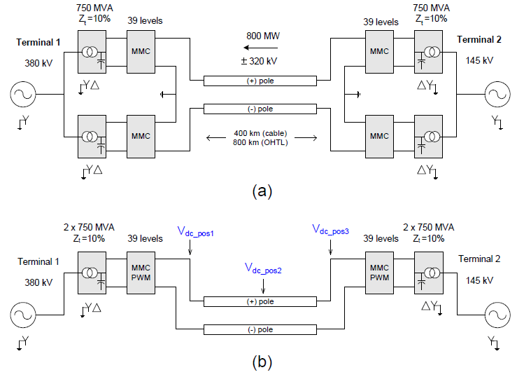
According to their topology, HVDC systems can be classified into various categories. However, for the purpose of this study, the configurations utilized are: a symmetrical monopole system, in which there is commonly no grounding system (Fig. 1a) and a bipolar system, with two converters in each end and where the returning path (with one pole out of service) can be accomplished through a metallic return or through the ground (Fig. 1b).
While the converters in LCC-HVDC applications use thyristors and can only control active power, the VSCHVDC configuration uses IGBTs (Insulated Gate Bipolar Transistors) as switching devices that can independently control both active and reactive power. This control is an important characteristic because in the LCC-HVDC alternative, the reactive power required by the converters, as well as the required filters, must be provided locally. Another important issue is that, due to the turn on/off characteristic of the IGBTs, the resulting voltage waveform is close to a sine wave, thereby requiring much smaller filters in the AC side.
The presence of overvoltages in DC systems using VSC-HVDC can be due to various causes, namely, faults in the system, loss of the inverter terminal, loss of load, etc. The reconnection of the rectifier, once it has been blocked, e.g., due to a fault, can also be responsible for the presence of overvoltages [1].
In underground cables, due to their physical separation and arrangement, the occurrence of pole-to-pole faults is rare. In contrast, DC overhead lines may be more prone to face such type of faults. Pole-to-pole faults are of special concern because it may cause failure of the semiconductor devices [2].
Within the VSC-HVDC technology, the Modular Multilevel Converter (MMC) has recently gained popularity due to its inherent advantages, namely: lower switching losses (i.e., lower switching frequency in each submodule), lower voltage across each switch (as only small capacitors are used in parallel with each switch), among others [3].
Recently, some MMC simulation models aimed at speeding up the computational time were proposed. For example, a detailed description of the MMC ‘average model’ and its dynamic performance under both balanced and unbalanced grid operation modes are presented in [4], [5] and [6]. A revision of the methods typically used for the protection of VSC-based HVDC systems is presented in [7]. The referred article, however, chiefly focuses on the overcurrent protection. The overvoltage protection and insulation coordination in MMC-based HVDC systems are explored in [8]. All DC lines in this reference are submarine cables, and the study conducted is focused on the insulation design of the DC line.
The effect of DC faults and their respective protection scheme in VSC-multi-terminal high voltage direct current (MTDC) transmission systems is presented in [9]. The scheme uses IGBT-based circuit breakers and its respective coordination with the converter switches (IGBTs) to block the converter during fault periods.
When a line-to-ground fault occurs in a bipolar system, the faulted pole rapidly discharges the capacitor(s) to ground. This discharge causes an imbalance of the DC link voltage between the positive and negative poles. As the voltage of the faulted line begins to fall, high currents flow from the capacitor(s) as well as from the AC grid. These high currents may damage the converters and the capacitors [10].
During faults in the DC link of a VSC-HVDC system, and also during contingencies in the AC system (involving line and/or transformers) nearby the converter stations, some overvoltages in the DC line can appear. Such overvoltages are of concern because they may have an influence on the design of the line and on the surge arresters located on the DC side of the converters.
In view of these design considerations, this article presents the magnitude of the overvoltages arising from faults occurring inside the DC link. In addition, the effect of line disconnections in another neighbouring AC grid configuration, due to inherent faults, is also presented.
Description of the DC System
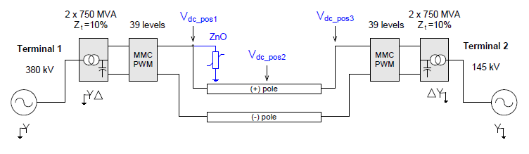
The VSC-HVDC system used here is based on the MMC technique. Additionally, the MMC converter referred to as Model 2 in [5] was used herein. A two-pole 400-km DC cable and an 800-km overhead line were independently used in the DC link of the point-to-point DC system. The nominal DC voltage and transmitted power are equal to ±320 kV and 800 MW, respectively. Both bipolar and symmetrical monopole systems, along with the AC voltages and transformer characteristics, are shown in Figs. 2(a) and 2(b), respectively. The direction of the power flow shown in these figures was set to occur from Terminal 2 to Terminal 1; however, it could also be set to flow in the opposite direction.
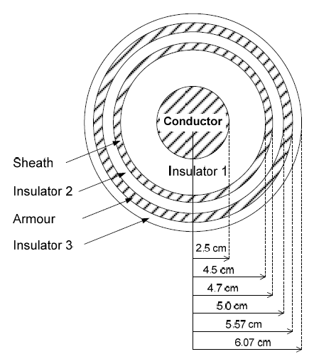
Regarding the DC link, both positive and negative cables have standard configurations, with a core (whose diameter is equal to 0.05 m), sheath and armour, as described in the Appendix section. The separation distance between both cables is 0.5 m, and the cables are buried at a depth of 1.5 m.
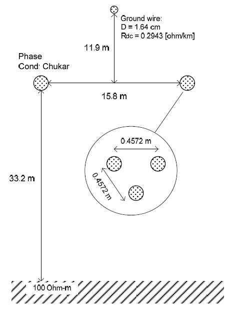
The overhead transmission line (OHTL) considered has a bundle of three ACSR conductors per pole (Chukar conductor) located at a height of 33.2 m at the tower and 14.1 m at midspan. The ground resistivity considered in both cases (i.e., cable and OHTL) was equal to 100 Ω–m. Likewise, a fault resistance equal to 0.01 Ω was considered in all the simulations.
Overvoltage Analysis
Both symmetrical monopole and bipolar VSC-HVDC systems were simulated using the PSCAD program [11] with the EMTDC as its numerical solver. For some other calculations the EMTP-RV program [12], was also used. The following faults were analysed for both the cable and the OHTL case:
a) Symmetrical Monopole System
1. Pole-to-pole fault
2. Pole-to-ground fault
b) Bipolar System
1. Pole-to-pole fault
2. Pole-to-ground fault
In all simulated cases, the fault (applied at t = 3.0 s and extinguished forcedly after 200 ms) was assumed to occur in the middle of the DC link (negative pole). This is because this point is one of the most critical in terms of overvoltage.
Overvoltages due to Faults in the DC Link During a fault in the DC link, two instants of overvoltage normally occur. The first one occurs at the beginning of the DC fault itself. The second one occurs at the instant when the fault is cleared. The major concern here is the overvoltages during the fault period. Note that independently of the power flow direction, both equivalent sources contribute to the fault current.
Next, the overvoltages and the behaviour of the DC link, due to the simulated faults, will be shown. The magnitude of the overvoltages at the beginning (Vdc_pos1), the middle (Vdc_pos2), and the end of the DC line (Vdc_pos3), as indicated in Fig. 2(b), will be presented. Measurements at these same points of the negative pole were also obtained. However, our main focus will be on the overvoltages created in the sound pole. A summary of all the values obtained in the study is presented in Table 1.
A. Use of a Cable in the DC Link
a) Symmetrical Monopole System
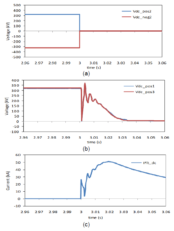
1. Pole-to-pole fault
The voltage at the fault point in both sound and faulted pole (Vdc_pos2 & Vdc_neg2) falls to zero (Fig. 3a), whereas the peak overvoltages at Vdc_pos1 and Vdc_pos3 (sound pole) are 369 kV and 372 kV, respectively (Fig. 3b). The peak of the DC current (20 ms after the fault was initiated) was approximately 51 kA (Fig. 3c).
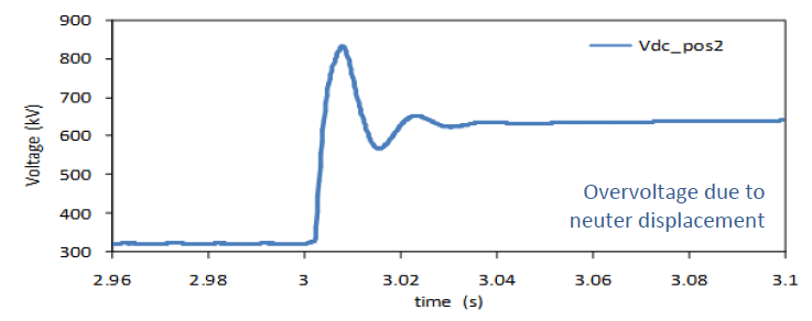
2. Pole-to-ground fault
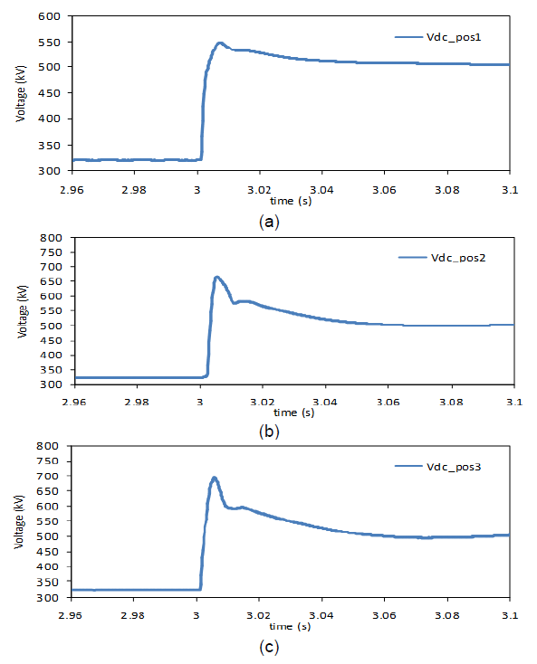
While the voltage at the negative pole (faulted pole) drops to a very low value (close to zero), the sound pole exhibits a significantly large peak overvoltage at the middle of the line (Vdc_pos2 =834 kV), as depicted in Fig. 4. The maximum overvoltages read at both the beginning and end of the sound pole (Vdc_pos1 & Vdc_pos3) were approximately 782 kV. These overvoltages are mainly due to the displacement of the (virtual) neutre in the DC link of the symmetric monopole system. Under the no fault conditions, this virtual reference is zero, with each pole operating at ±320 kV. The instant the negative pole drops nearly to zero (due to the fault) this reference is displaced; thus, resulting in higher DC voltages on the sound pole.
b) Bipolar System
1. Pole-to-pole fault
Close results to those presented in Section A.a.1 were obtained (i.e., the voltages at the middle point Vdc_pos2 and Vdc_neg2, fall to zero; whereas the values of Vdc_pos1 and Vdc_pos3 are equal to 302 kV and 305 kV, respectively). The peak fault current was equal to 33.7 kA.
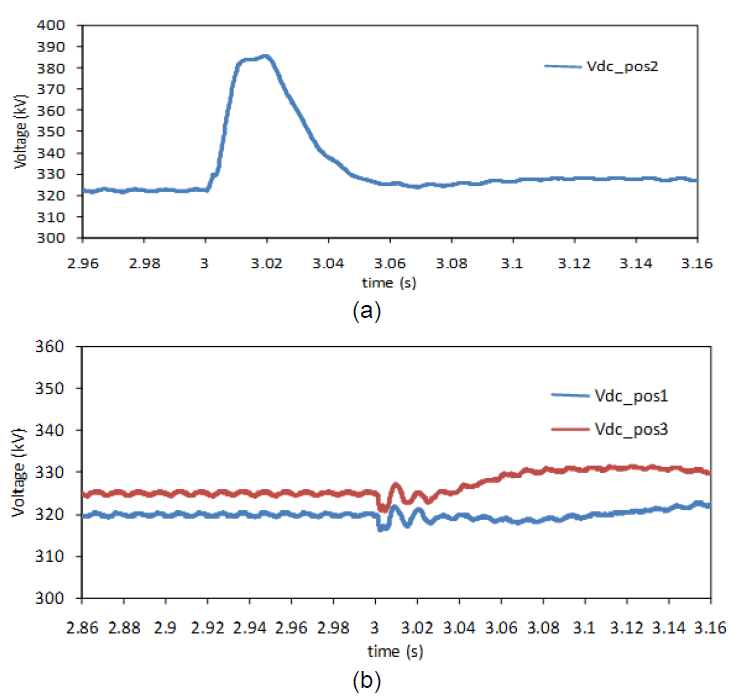
2. Pole-to-ground fault
The peak overvoltage at the sound pole (Vdc_pos2) was equal to 386 kV (Fig. 5a), whereas at each end of the line relatively lower voltages (Vdc_pos1 = 323 kV and Vdc_pos3 = 332 kV) were obtained (Fig. 5b). These overvoltages can present no threat to the analysed system.
B. OHTL as DC Link
a) Symmetrical Monopole System
1. Pole-to-pole fault
The peak overvoltages read at Vdc_pos1 and Vdc_pos3 were 385 kV and 382 kV, respectively. As expected, the voltage at the middle of both poles fell to zero. The value of the peak fault current was approximately 35.7 kA.
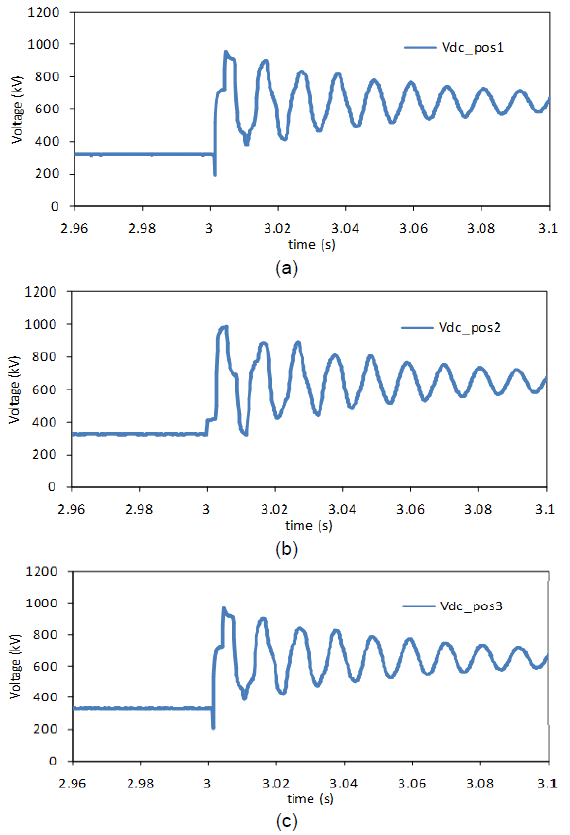
2. Pole-to-ground fault
The greatest peak overvoltage at the sound pole is approximately 989 kV (Vdc_pos2 shown in Fig. 6b). In Figs.6(a) and 6(c), the values at each end of the DC line (Vdc_pos1 = 956 kV and Vdc_pos3 = 969 kV) are shown. The peak of the fault current was approximately 2.6 kA.
b) Bipolar System
1. Pole-to-pole fault
The peak overvoltages at the beginning and end of the DC line were 433 kV (Vdc_pos1) and 422 kV (Vdc_pos3), as shown in Fig. 7. The peak of the fault current was approximately 26 kA.
2. Pole-to-ground fault
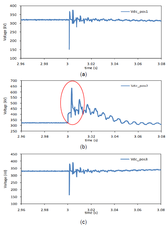
The peak overvoltage at the sound pole (Vdc_pos2 in Fig.8b) was approximately 634 kV. The values at both ends of the line were: Vdc_pos1 = 376 kV (Fig. 8a) and Vdc_pos3 = 394 kV (Fig. 8c). The maximum value of the fault current was equal to 18.4kA.
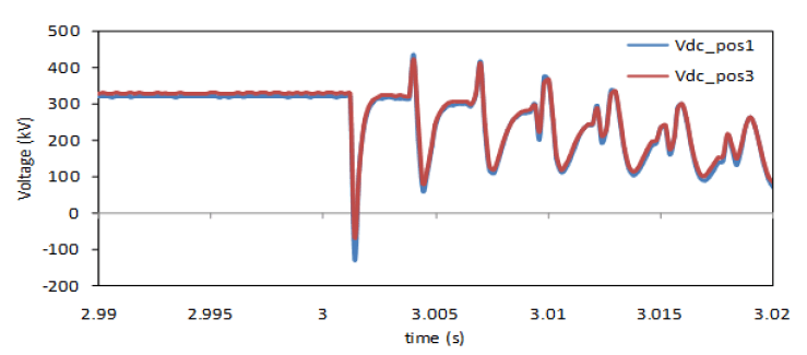
The overshoot inside the ellipse shown in Fig. 8(b) is also due to the contribution of the travelling waves along the DC line. This overshoot (further amplified in Fig. 9) coincides with the time taken by the travelling wave after bouncing off the converter stations at both ends (i.e., 2.8 ms after the occurrence of the fault). If in this particular conductor (OHTL) the wave propagation speed is close to the speed of light, it can be shown that the total distance travelled by this wave is equal to the length travelled on the DC line (i.e. 2×400 km in 2.8 ms). Each fast travelling wave (depicted in Fig. 10) bounces in each end of the line creating reflections which when added to the existing overvoltage it can reach values twice or more of those encountered during normal conditions.
From Table 1, it can be seen that pole-to-pole faults have the highest fault currents. Pole-to-ground faults in the case of the monopole system exhibit the highest overvoltages. Faults occurring in the DC link of the bipolar system do not create very significant overvoltages that could threaten the line’s BIL (Basic Impulse Insulation Level). The minimum BIL calculated for equipment within the substation was equal to 750 kV, whereas the BIL for the DC line resulted in 1900 kV. According to [13], the latter critical flashover voltage corresponds to a 300 kV line whose insulator chain has 18 standard disc insulators.
Also, faults occurring in the dc cable resulted in relatively higher fault currents compared to the values obtained for the OHTL case (Table 1). An opposite behaviour was observed for the case of the overvoltages (i.e. the DC cable exhibited relatively lower overvoltages in relation to the OHTL).
Despite these overvoltages do not seriously threaten the line’s insulation level, it is also necessary to assess the surge arresters effectiveness for reducing such overvoltages. Such analysis is presented in the subsequent section.
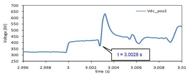
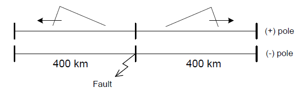
Table 1. Overvoltage for the different type and fault configurations
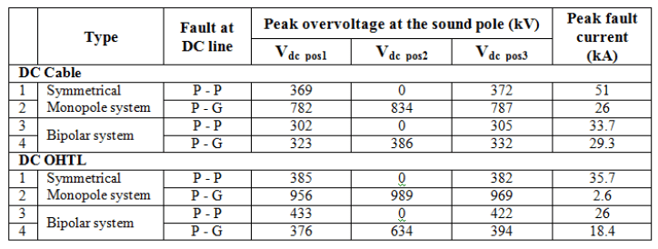
P-G: Pole-to-ground fault.
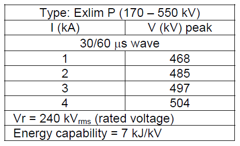
Use of Surge Arresters Zinc Oxide (ZnO) arresters are commonly used for the protection against overvoltages in AC and DC systems. So, a ZnO arrester was placed at point Vdc_pos1 (sound pole), as depicted in Fig. 11. The rated voltage of the selected surge arrester is 240 kV (rms). Its V-I curve is presented in the Appendix. Additionally, the maximum energy that this particular arrester can absorb is 7 kJ/kV.
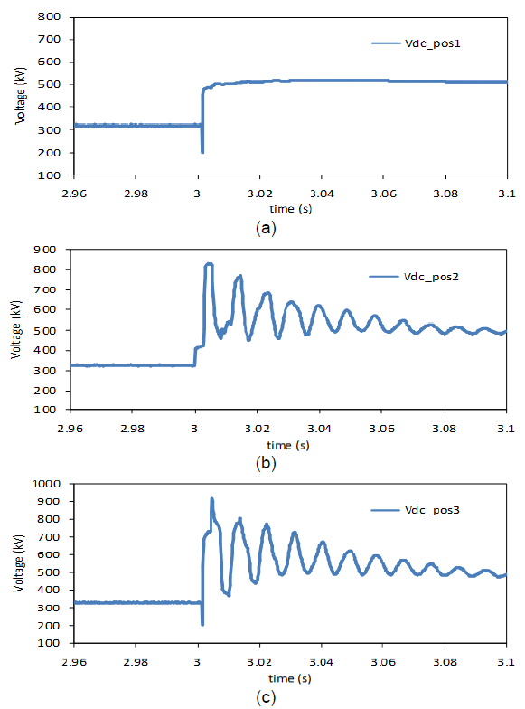
The results obtained after the installation of a surge arrester for the symmetrical monopole configuration (pole-to-ground fault) when the DC link separately uses a cable and an OHTL, are presented in Figs. 12 and 13, respectively.
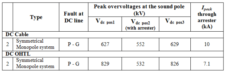
The reason for initially placing only one arrester is to better observe the effect of this overvoltage suppressor at a particular point along the line, in this case point Vdc_pos1. In practice, one arrester should be placed at each end and in each pole of the DC link. For both, cable and OHTL, the overvoltage at the protected point (Vdc_pos1) was effectively reduced to the arrester protection level (549 kV in Fig. 12a and 517 kV in Fig. 13a), but remained high in the other unprotected points.
In Table 2, a summary of the voltages measured at Vdc_pos1, Vdc_pos2 and Vdc_pos3 is presented.
Subsequently, the surge arrester was taken to the middle of the line (positive pole). Although this option (surge arrester at middle of the line) might sound a bit uncommon, it can actually be the case of installing a “line” surge arrester on the tower itself, similar to the installation of line arresters in some ac systems.
In Table 3, the reduction of the overvoltage at point Vdc_pos2 (552 kV/320 kV=1.75 pu cable; and 532 kV/320 kV =1.66 pu OHTL) for the symmetrical monopole system, is presented. However, as expected, the voltages close to Terminals 1 and 2 (with no arresters) are still high, above 1.95 pu at both line ends. Therefore, it will be necessary to install surge arresters in more than one point.
So, surge arresters in the middle and at both ends of the DC line were placed. The three arresters effectively reduced the DC link overvoltages to the arresters protection level (Table 4). A brief analysis on the energy absorbed by the arresters is presented in Section 6.
Table 2. Overvoltage reduction at Vdc_pos1 after the installation of the ZnO surge arresters.
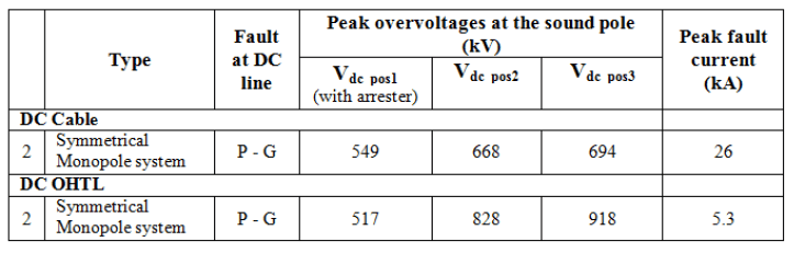
Table 3. Overvoltages at the sound pole with surge arrester installed only at middle of the (+) pole.
DC cable case: Earr2 = 407.7 MJ
OHTL case: Earr2 = 376.4 MJ
Table 4. Voltages at the sound pole with surge arresters installed at the three points.
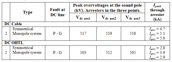
DC cable case: Earr1 = 156.8 MJ, Earr2 = 162.8 MJ, Earr3 = 144.8 MJ.
OHTL case: Earr1 = 151.5 MJ, Earr2 = 153.6 MJ, Earr3 = 138.1 MJ
Energy Absorbed by the Specific Surge Arrester(s)
During prolonged (sustained) overvoltage conditions a considerably large amount of energy might need to be absorbed by the arrester. This high energy absorbed might threaten the operation of the installed surge arrester. The energy absorbed by a single arrester located at point Vdc_pos1 (Energ_p1) is shown in Fig. 14. It can be observed that the energy absorbed keeps rising beyond the arrester’s limit (1700 kJ) which imposes a high risk of damage to the arrester.
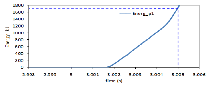
Now, if it is to prevent the arrester from being damaged, the DC line should be disconnected in less than 5 ms after the fault has started (at t = 3.0 s), as indicated by the segmented line of Fig. 14. The installation of three arresters (at both ends and the middle of the positive pole) also reduced significantly the energy absorbed by each arrester (see Table 4). The negative pole (line) will also require similar arresters at the same locations as those indicated for the positive pole. Closer values of the absorbed energy were obtained after the installation of surge arresters in the point-to-point system using a cable as the DC link. An alternative proposal is the installation of a resistor and chopper with sufficient energy capability at both stations.
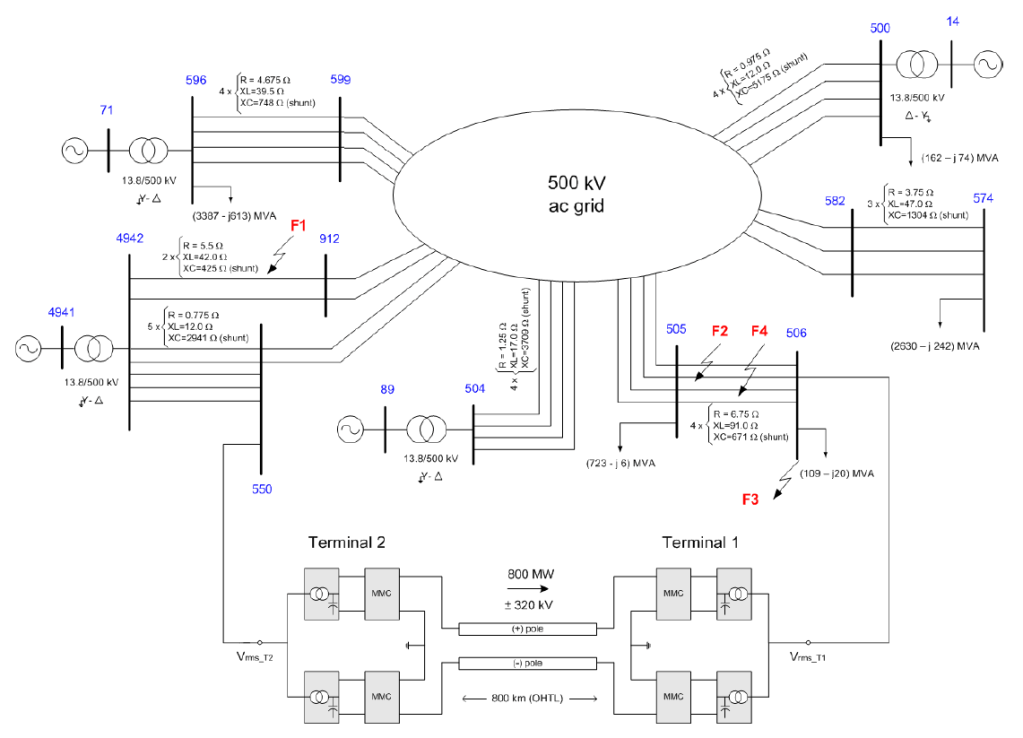
Response of the Bipolar HVDC System Towards Faults Occurring in a Nearby AC System The point-to-point bipolar system depicted in Fig. 2(a) was embedded into a digital model of an existing AC grid, whose operating voltage is equal to 500 kV (see Fig. 15). Four AC equivalent generators feed the entire AC grid (60 Hz). All of the transmission line parameters were represented through coupled pi sections to consider their values of series impedance and shunt admittance. To conduct this analysis, the set points of the transmitted power and the voltage of the point-to-point bipolar system were kept at 400 MW/pole and +/-320 kV/pole, respectively.
Whenever an event during t(-) to t(+) in the AC system occurs (near either DC link terminal), there will be a change in the voltage angles at buses 550 and 506. The t(-) time refers to the instant just before the event, whereas t(+) refers to the instant just after the event. The angle of the AC voltage generated by the VSC remains the same from the time prior to the event occurrence. From t(-) to t(+) there will occur a change in the active power of the converters at terminals 1 and 2. The resulting (instantaneous) imbalance in these powers change the voltage in the DC line; thus, the DC voltage may increase or otherwise decrease (e.g. if the input power + losses + output power within the VSC-HVDC scheme increase; then, the DC voltage will rise, boosted by the DC link capacitor, conversely, the DC voltage will decrease). After a certain time, the controls of the converters bring both powers (P1 and P2) to the pre-event condition. The presence of this type of event in the AC system shall be simulated to check the extent these DC overvoltages are and the amount of stress that they can cause upon the DC arresters.
Four types of events were applied: F1: three-phase-to-ground fault (at t = 4.0s) after which the affected line (912 – 4942) trips off at t = 4.1 s (duration of fault: 200 ms); F2: sudden permanent disconnection of two parallel lines located between buses 505-506; F3: three-phase–to-ground fault (at bus 506) through a 25 Ω reactor (fault is removed after 100 ms) and, F4: three-phase fault that causes the simultaneous permanent disconnection of three parallel lines located between buses 505-506. In all cases, low oscillations of the overvoltages were observed; however, they did not affect the DC line arresters located at the same three points of each pole. As an example, the results of the disconnection of three parallel lines between buses 505-506 (Fault F4) are presented (Figs. 16 and 17).
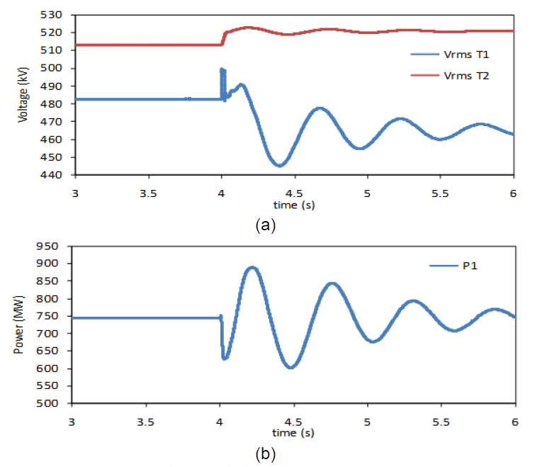
(Vrms_T1 = 482 kV & Vrms_T2 = 513 kV) are shown in Fig. 16(a). Notice that with the disconnection of the three lines between buses 505 and 506, the rms voltage at Terminal 1 (closer to the fault point) reaches a new operative point (around 460 kV) in relation to the pre-fault value (482 kV). This is partly due to the higher losses now present in the remaining line. In order to ensure a proper operation of the converters, this voltage drop will have to be compensated by the transformer tap changer.
The rms voltages (AC side) of Terminals 1 and 2 (Vrms_T1 = 482 kV & Vrms_T2 = 513 kV) are shown in Fig. 16(a). Notice that with the disconnection of the three lines between buses 505 and 506, the rms voltage at Terminal 1 (closer to the fault point) reaches a new operative point (around 460 kV) in relation to the pre-fault value (482 kV). This is partly due to the higher losses now present in the remaining line. In order to ensure a proper operation of the converters, this voltage drop will have to be compensated by the transformer tap changer.
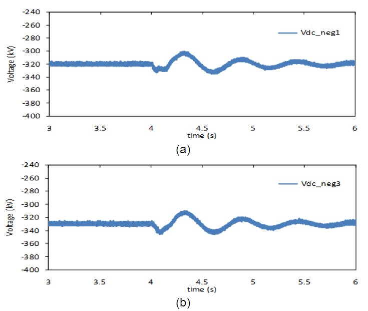
The oscillation and subsequent damping of the AC power (in around 3.0s) at Terminal 1 (P1) is shown in Fig. 16(b). Low oscillatory patterns of the voltages in the negative pole (peak values equal to Vdc_neg1 = 340 kV and Vdc_neg3 = 348 kV) were also observed for this fault (Fig. 17a and 17b, respectively). In conclusion, no significant threats over the DC link from faults occurring in a nearby ac system were found.
Conclusions
From the study conducted on the overvoltage condition due to faults regarding the operation of a point-to-point bipolar system, the following conclusions can be drawn:
– Pole-to-ground faults on the DC link of a symmetrical monopole system may give rise to high overvoltages on the DC side. This condition should be considered while developing a VSC-HVDC project.
– Sustained overvoltages due to prolonged faults on the DC link can threaten, and can even destroy, the normal operation of the surge arresters installed on the DC side. Therefore, it is recommended that the DC line be opened soon after (in this case in less than 5 ms) the occurrence of the fault.
– Overvoltages due to the faults occurring inside neighbouring AC grids may have an impact on the VSCHVDC system. Therefore, to evaluate the performance of the DC link, it is also important to determine the magnitude of such overvoltages. Regarding the analysed network, those overvoltages exhibited low non-jeopardizing values.
Appendix
All AC sources were represented as sources behind the source impedance.
AC source at Terminal 1 (Fig.2):
Vrms : 380 kV
Rseries : 0.15335 Ω
Rparallel : 100 MΩ
Lparallel : 15.31 mH
AC source at Terminal 2:
Vrms : 145 kV
Rseries : 0.0222 Ω
Rparallel : 100 MΩ
Lparallel : 2.23 mH
Characteristics of the surge arrester:
Table A1. V-I curve of the surge arrester used.
All data used in this article can be willingly sent upon request.
Cable dimensions:
OHTL dimensions:
REFERENCES
[1] Lu W. and Ooi B., DC Overvoltage Control during Loss of Converter in Multiterminal Voltage Sourced Converter Based HVDC (M-VSC-HVDC), IEEE Transactions on Power Delivery, Vol. 18, No. 3, pp. 915–920, July 2003.
[2] García Alonso J. C., Mosallat F., Wachal R., Abdel-Hadi K., Half and Full Bridge MMC Fault Performance in VSC-HVDC Systems. In: CIGRE CE B4 Colloquium: HVDC and Power Electronics to Boost Network Performance, Brasilia, Oct. 2-3,pp. 1-7.
[3] Lesnicar A., Marquardt R., An Innovative Modular Multi-Level Converter Topology for a Wide Power Range. IEEE Power Tech Conference, Bologna, Italy, June 2003.
[4] Peralta J., Saad H., Dennetiére S., Mahseredjian J., Nguefeu S., Detailed and Averaged Models for a 401-Level MMC–HVDC System. IEEE Transactions on Power Delivery, Vol. 27, No. 3, JUL. 2012. pp. 1501-1508. DOI: 10.1109/TPWRD.2012.2188911
[5] Saad H., Dennetiere S., Mahseredjian J., Delarue P., Guillaud X., Peralta J., Nguefeu S., Modular Multilevel Converter Models for Electromagnetic Transients. IEEE Transactions on Power Delivery, Vol. PP, No. 99, 2013. DOI. 10.1109/TPWRD.2013.2285633
[6] Saeedifard M., Iravani R., Dynamic Performance of a Modular Multilevel Back-to-Back HVDC System. IEEE Transactions on Power Delivery, Vol. 25, No. 4, 2010. pp. 2903-2912.
[7] Candelaria J., Park J-D., VSC-HVDC System Protection: A Review of Current Methods. In: Proc. of the IEEE/PES Power Systems Conf. and Exp. (PSCE), Phoenix (AZ), 20-23 Mar.pp.1-7. DOI: 10.1109/PSCE.2011.5772604
[8] Gu Y., Huang X., Qiu P., Hua W., Study of Overvoltage Protection and Insulation Coordination for MMC based HVDC. In: Proc. of the 2nd Int. Conf. on Computer Science and Electronics Engineering (ICCSEE 2013), Atlantis Press, Paris, pp. 2369-2372.
[9] Tang L., Ooi B-T., Protection of VSC-Multi-Terminal HVDC against DC Faults. In: Proc. of the IEEE 33rd Annual Power Electronics Specialists Conf (PESC 02), Vol. 2, Cairns, Australia, Jun. 23-27, 2002. pp. 719-724. DOI: 10.1109/PSEC.2002.1022539.
[10] Yang J., Zheng J., Tang G., He Z., Characteristics and Recovery Performance of VSC-HVDC DC Transmission Line Fault. In: Asia Pacific Power and Energy Engineering Conference (APPEEC), Chengdu, pp. 1–4, April 2010.
[11] PSCAD/EMTDC® Program. Manitoba HVDC Research Centre, v.4.3.1.0 (x4), 2010.
[12] EMTP-RV, Electromagnetic Transients Program, v. 2.6, 2013.
[13] CIGRE B2/B4/C1.17, Impacts of HVDC Lines on the Economics of HVDC Projects. No. 388, Aug. 2009.
Authors: prof. dr. Jose Antonio Jardini, Polytechnic School of the University of Sao Paulo, E-mail: jose.jardini@gmail.com; dr. Ricardo Leon Vasquez-Arnez, Foundation for the Technological Development of the Engineering Sciences (FDTE), E-mail: ricardoleon00@yahoo.co.uk; msc. Marcos T. Bassini, Polytechnic School of the University of Sao Paulo, E-mail: mtbassini@gmail.com; msc. Marco Antonio Barbosa Horita, Polytechnic School of the University of Sao Paulo, E-mail: marcoabh@gmail.com; msc. Gerson Yukio Saiki, Foundation for the Technological Development of the Engineering Sciences (FDTE), E-mail: gsaiki@fdte.org.br; Marcos Rodolfo Cavalheiro, CTEEP Sao Paulo State Power Transmission Company, E-mail: mcavalheiro@cteep.com.br.
The correspondence address is: e-mail: ricardoleon00@yahoo.co.uk
Source & Publisher Item Identifier: PRZEGLĄD ELEKTROTECHNICZNY, ISSN 0033-2097, R. 91 NR 8/2015. doi:10.15199/48.2015.08.26
