Published by Electrical Installation Wiki, Chapter J. Overvoltage protection – Installation of Surge Protection Device
Connection of Surge Protection Device
Connections of a SPD to the loads should be as short as possible in order to reduce the value of the voltage protection level (installed Up) on the terminals of the protected equipment.
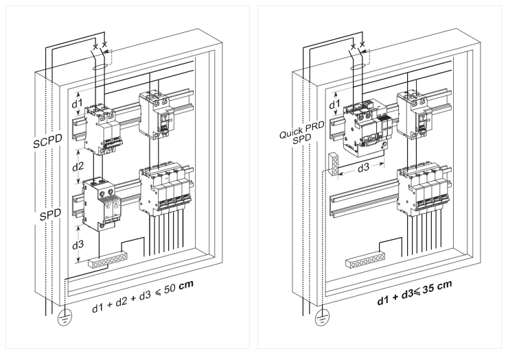
The total length of SPD connections to the network and the earth terminal block should not exceed 50 cm.
One of the essential characteristics for the protection of equipment is the maximum voltage protection level (installed Up) that the equipment can withstand at its terminals. Accordingly, a SPD should be chosen with a voltage protection level Up adapted to protection of the equipment (see Fig. J38). The total length of the connection conductors is
L = L1+L2+L3.
For high-frequency currents, the impedance per unit length of this connection is approximately 1 µH/m.
Hence, applying Lenz’s law to this connection: ΔU = L di/dt
The normalized 8/20 µs current wave, with a current amplitude of 8 kA, accordingly creates a voltage rise of 1000 V per metre of cable.
ΔU =1 x 10-6 x 8 x 103 /8 x 10-6 = 1000 V
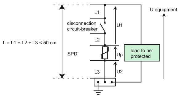
As a result the voltage across the equipment terminals, U equipment, is:
U equipment = Up + U1 + U2
If L1+L2+L3 = 50 cm, and the wave is 8/20 µs with an amplitude of 8 kÂ, the voltage across the equipment terminals will be Up + 500 V.
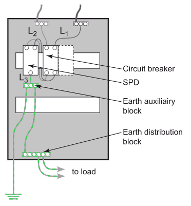
Connection in plastic enclosure
Figure J39 below shows how to connect a SPD in plastic enclosure.
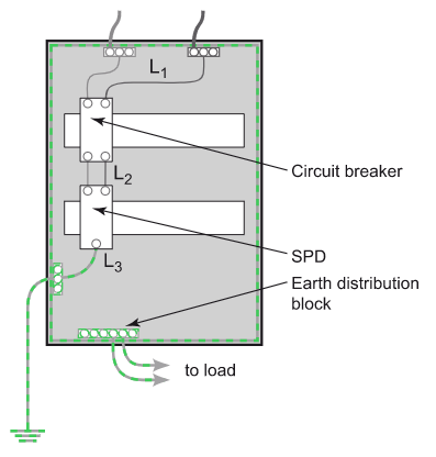
Connection in metallic enclosure
In the case of a switchgear assembly in a metallic enclosure, it may be wise to connect the SPD directly to the metallic enclosure, with the enclosure being used as a protective conductor (see Fig. J40).
This arrangement complies with standard IEC 61439-2 and the Assembly manufacturer must make sure that the characteristics of the enclosure make this use possible.
Conductor cross section
The recommended minimum conductor cross section takes into account:
• The normal service to be provided: Flow of the lightning current wave under a maximum voltage drop (50 cm rule).
Note: Unlike applications at 50 Hz, the phenomenon of lightning being high-frequency, the increase in the conductor cross section does not greatly reduce its high-frequency impedance.
• The conductors’ withstand to short-circuit currents: The conductor must resist a short-circuit current during the maximum protection system cutoff time.
IEC 60364 recommends at the installation incoming end a minimum cross section of:
• 4 mm2 (Cu) for connection of Type 2 SPD;
• 16 mm2 (Cu) for connection of Type 1 SPD (presence of lightning protection system).
Examples of good and bad SPD installations
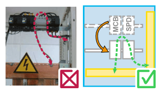
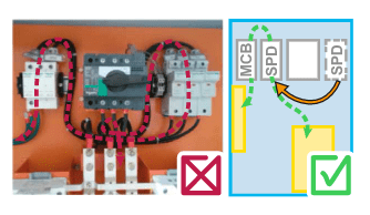
Fig. J41 – Examples of good and bad SPD installations
Cabling rules of Surge Protection Device
Rule 1
The first rule to comply with is that the length of the SPD connections between the network (via the external SCPD) and the earthing terminal block should not exceed 50 cm.
Figure J42 shows the two possibilities for connection of a SPD.
Rule 2
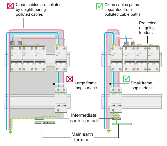
The conductors of protected outgoing feeders:
• should be connected to the terminals of the external SCPD or the SPD;
• should be separated physically from the polluted incoming conductors.
They are located to the right of the terminals of the SPD and the SCPD (see Figure J43 ).
Rule 3
The incoming feeder phase, neutral and protection (PE) conductors should run one beside another in order to reduce the loop surface (see Fig. J44).
Rule 4
The incoming conductors of the SPD should be remote from the protected outgoing conductors to avoid polluting them by coupling (see Fig. J44).
Rule 5
The cables should be pinned against the metallic parts of the enclosure (if any) in order to minimize the surface of the frame loop and hence benefit from a shielding effect against EM disturbances.
In all cases, it must be checked that the frames of switchboards and enclosures are earthed via very short connections.
Finally, if shielded cables are used, big lengths should be avoided, because they reduce the efficiency of shielding (see Fig. J44).
Source URL: https://www.electrical-installation.org/enwiki/Installation_of_Surge_Protection_Device
