Published by Anna KOZIOROWSKA1,2, Dariusz SOBCZYŃSKI3, Wiesława MALSKA3
Uniwersytet Rzeszowski, Wydział Matematyczno – Przyrodniczy, Instytut Techniki (1)
Uniwersytet Rzeszowski, Centrum Biotechnologii Stosowanej i Nauk Podstawowych (2)
Politechnika Rzeszowska, Wydział Elektrotechniki i Informatyki, Katedra Energoelektroniki i Elektroenergetyki (3)
Abstract: Specialized biomedical laboratory equipment, very often use power converters, which are a source of higher harmonics. These devices depending on their functions consist of several additional elements (e.g.: UV lamp, heater),and give the possibility of speed control. These devices are most often used in analytical laboratories and research biomedical and biotechnological laboratories.
Streszczenie. Specjalizowane biomedyczne urządzenia laboratoryjne, bardzo często wykorzystują przekształtniki energoelektroniczne, które są źródłem wyższych harmonicznych. Urządzenia te w zależności od swoich funkcji składają się z kilku dodatkowych elementów (np.: lampa UV, grzałka), a dają możliwość regulacji prędkości. Urządzenia tego typu stosowane są najczęściej w laboratoriach analitycznych oraz w biotechnologicznych laboratoriach naukowo-badawczych. (Badania biomedycznych urządzeń laboratoryjnych pod kątem generacji zakłóceń)
Słowa kluczowe: odkształcenia napięcia i prądu, wyższe harmoniczne, urządzenia laboratoryjne
Keywords: Voltage and Current Distortion, Higher Harmonics, biomedical laboratory equipment
Introduction
Converters AC/DC are now widely used in many fields of technology, ranging from households and business services to industry, power generation, ending on telecommunications, the aerospace. The purpose of power converters using in consumer devices is mainly the reduction of energy consumption and lower operating costs. There is also important the construction and appropriate control of power electronic devices that from the point of view of the power supply network reduce the negative impact of this type of power converters on the power supply network [1,2,3,4]. This paper presents the results of measuring tests of influence on supply network of ultracentrifugation and electrophoresis system [5,6,7,8,10,11].
The study was conducted in the laboratory of the Institute of Applied Biotechnology and Basic Sciences University of Rzeszow in Werynia.
Characteristics of laboratory equipment
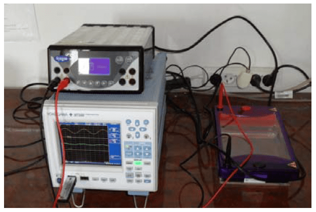
The phenomenon of electrophoresis is the movement of charged particles relative to the solvent under the influence of the applied electric field. Areas of application of electrophoresis phenomenon are biochemistry of nucleic acids and proteins, molecular biology, and medical diagnostics [9]. An example of the application of this phenomenon is the DNA electrophoresis, which allows separation of particles due to their volume. DNA moves in the electric field and the applied gel resists proportional to particle size. Different particles move at different speeds – small rapidly, and large slowly. There are formed stripes, the groups of molecules of the same size. In the laboratory of Center of Applied Biotechnology and Basic Sciences there is installed the electrophoresis kit, which was tested for the impact of nonlinear devices on the quality of electric energy (photo 1).
Centrifugal extractors are popular devices used in analytical laboratories for the separation of mixtures into components of different densities. They are used in research of genetic engineering. They can be used in microbiology laboratories, biochemical, clinical and industrial applications. Due to the fast rotation of the fluid it is possible to separate the lighter components from the heavier. Heavier components will be located away from the axis of rotation. Due to the speed of rotation centrifugal extractors can be divided into three groups: low speed at up to 5 000 rpm, medium speed – up to 20 000 rpm and ultra speeds of more than 20 000 rpm.
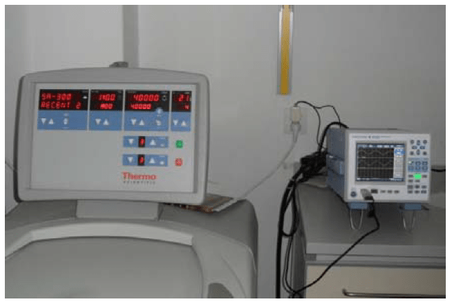
In the study there was used the centrifuge Thermo Scientific Sorvall Legend. It is dedicated to the cell culture, bioproduction and separation of blood cells. Cooling systems used in the centrifuge allows to control the temperature of the sample and the chamber between -10°C and +40°C. Maximum speed is 12 000 rpm, and the power of 1400 W. There is used brushless induction motor drive in the centrifuge. There were made the measurement tests of currents and voltages of Thermo Scientific Sorvall Evolution and its influence on quality of electric energy. This device is designed for high performance samples and is used very often in specialized laboratories.
Results of measurement tests
In order to analyze the work of selected biomedical laboratory equipment in terms of their impact on the supply network there were measured selected parameters at the Laboratory of Biotechnology in Institute of Applied Biotechnology and Basic Sciences. Laboratory equipment is used for scientific research in the field of biotechnology. As the evaluation measure of harmonic distortion factor there were adopted the factor of harmonic content THD (Total Harmonic Distortion) and individual distortion factor HD (Individual Harmonic Distortion) [8,10].
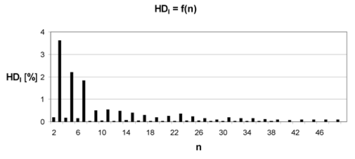
Individual Harmonic Distortion of centrifuge current (Fig. 2), shown in Figure 1 for standby operating status and temperature inside the centrifuge equal 4°C indicates a not very large deformation of the supply current, and the value of THD for the current is 9.97% (THD value of the voltage is 1.73%).

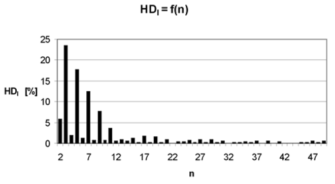
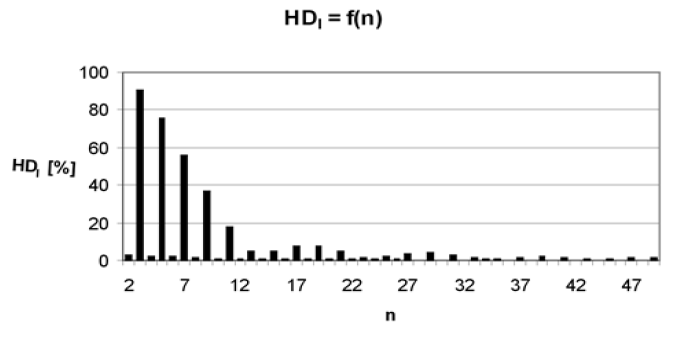
Figure 2 shows a ratio of HD for operating state with a fixed rotation speed equal to 12 000 rpm and operating of the refrigerator in order to reduce the temperature inside the centrifuge chamber to 4°C. For this case there was measured THD ratio of current equal to 33.8% (the value of the voltage THD was 2.25%). For a fixed centrifuge operation at a speed equal to 12 000 rpm and a fixed temperature of 4°C, there was a significant increase in the HD coefficient – fig. 3, which is also reflected in the current THD – equal in this case 137% (the value of the voltage THD was 2.17%).
Figures 4-6 show the waveforms of RMS current drawn by the centrifuge at different operating conditions, start from preparation to operation, by operation and cooling the chamber to 4°C, and from the start to the normal, stable operation at a speed of 12 000 rpm. Figure 4 shows the course of the RMS current of centrifuge over 170 seconds (start-up from standby to start centrifugation at 12 000 rpm, stop and restart). Waveforms allow for the classification of this biomedical laboratory equipment to a group of “Anxious” receivers.

Figure 5 shows the course of RMS current centrifuge within 170 seconds – from start-up status to stable operation at a speed of 752 rpm, for operating conditions on the first stage of speed control.
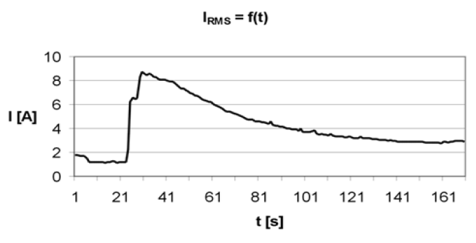
Figure 6 shows the course of RMS current of the centrifuge within 170 seconds. Lists the states of the centrifuge operation from starting and running the fifth stage of centrifugation speed control, ensures the spin speed 9 000 rpm, then turn off the device, restart, work and stop of the centrifuge.

For ultracentrifuge, which provides the spin speed to 60 000 rpm HD-value is very low. There is a low value of current THD too, it is equal 6,32%. For the case of Figure 7 the value of the voltage THD is 1.9%. And for the case of Figure 8 current THD equals 4.76% (the value of the voltage THD was 1.85%), reflecting the reduced negative impact of this type of devices on the power supply. Presented in Figures 7-8 individual harmonic distortion HD of the supply current of the ultracentrifuge confirms the high class of device and very low negative impact on the supply network. Harmonic amplitudes have also low values.


RMS current waveforms of the ultracentrifuge from the start operation state and set of the parameters of working up to the start-up and normal operation within 170 seconds are shown in Figure 9 This type of centrifuge is a device with a capacity of 3.5 kW, hence the large value of the current during the operation state.
In Figure 10 there is shown the gradual start-up of the device. On the top step of startup voltage decreased to a value of 212 V at RMS current 19 A. After startup there was a normal stable operation state with maintaining ultracentrifuge speed settings and keeping the recommended temperature inside the chamber.
There is interesting centrifuge stops in safe mode in 93 second of observation at a rotation speed 40 000 rpm restart, and normal operation state, shown in Figure 11.


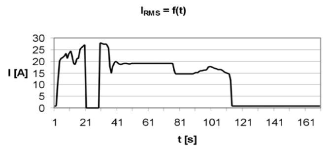


Shown in Figure 12 stopping of ultracentrifuge in “normal” mode in 75 second of observation at a rotation speed 40 000 rpm until the stop provides a very good design of control and regulation system. However, Figure 13 shows the course of RMS current of ultracentrifuge within 170 seconds from start-up and normal operation at a speed of 40 000 rpm and stop at “Normal” operating mode, restart, work and stop.
Among the analyzed biomedical laboratory equipment with the lowest power was kit for electrophoresis (photo 1). In Figures 14-15 there are presented the courses of RMS current of the electrophoresis system for two different load levels of the device.
Electrophoresis system dependency of individual supply current distortion in a normal operating state and voltage at 200 V and 300 mA is shown in Figure 16. For these conditions the value of current THD is 23.9% (the value of the voltage THD was 1.74%).
Summary
Based on laboratory tests, using a power meter Yokogawa WT 500 there can be evaluated the level of harmonics generated to the power system by a specialized biotechnological laboratory equipment. The results for ultracentrifuge suggest high class of the device and very low negative impact on the power network. Electrophoresis system has larger negative impact on the supply network, but it is a low-power electrical device which specific work is differs significantly from the dynamic specific work of the ultracentrifuge. Both tested devices affect on parameters of power supply network, but has little effect on other electric devices fed from the same power network. All tests shown in the paper will help to design the filter to reduce the higher harmonics generation
The study was performed within the project Centre of Applied Biotechnology and Basic Sciences supported by the Operational Programme Development of Eastern Poland 2007-2013, NoPOPW.01.03.00-18-018/09.
REFERENCES
[1] Barlik R., Nowak M.: Jakość energii elektrycznej – stan obecny i perspektywy. Przegląd Elektrotechniczny , nr 7-8 2005,
[2] Hanzelka Z.: Rozważania o jakości energii elektrycznej. Elektroinstalator nr 9/2001- 2/2002
[3] Malska W., Łatka M.: Wpływ odbiorników nieliniowych na parametry jakości energii elektrycznej, Wiadomości Elektrotechniczne, nr 10, 2007r.
[4] Nowak M., Barlik R.: Poradnik inżyniera energoelektronika, WNT, Warszawa 1998
[5] Paice Derek A.: Power electronic converter harmonics, IEEE Press, New York 1996
[6] Piróg S.: Energoelektronika: układy o komutacji sieciowej i o komutacji twardej), Uczelniane Wydawnictwa Naukowo-Dydaktyczne, AGH, 2006
[7] Strzelecki R., Supronowicz H.: Filtracja harmonicznych w sieciach zasilających prądu przemiennego, Postępy Napędu Elektrycznego, 1998
[8] Ustawa z dnia 10 kwietnia 1997 r. Prawo energetyczne. Dz.U. nr 54, poz. 348 z późniejszymi zmianami
[9] Kalinowska K., Ogórek R., Baran E. – Diagnostyka mikologiczna: wczoraj i dziś. Od mikroskopu do termocyklera, Mikologia Lekarska 2011, 18 (3): 156-158
[10] Bartman J., Koziorowska A., Kuryło K., Malska W. – Analiza rzeczywistych parametrów sygnałów elektrycznych zasilających układy napędowe pomp wodociągowych – Przegląd Elektrotechniczny, 2011/8, str. 8-11
[11] Norma PN-EN/50160 Parametry napięcia zasilającego w publicznych sieciach rozdzielczych. PKN 1998
[12] Rozporządzenie ministra gospodarki i pracy z dnia 20 grudnia 2004 r. w sprawie szczegółowych warunków przyłączenia do sieci elektroenergetycznych, ruchu i eksploatacji tych sieci. Dz.U. z 06.01.2005
[13] PN-EN 50160:2002 Parametry napięcia zasilającego w publicznych sieciach rozdzielczych.
[14] PN-T-03501:1998 Kompatybilność elektromagnetyczna (EMC). Dopuszczalne poziomy. Ograniczanie wahań napięcia i migotania światła powodowanych przez odbiorniki o prądzie znamionowym większym niż 16 A, w sieciach zasilających niskiego napięcia.
[15] [10] PN-EN 61000-3-2:1997 Kompatybilność elektromagnetyczna (EMC). Dopuszczalne poziomy. Dopuszczalne poziomy emisji harmonicznych
[16] prądu (fazowy prąd zasilający odbiornika mniejszy lub rowny 16 A).
[17] PN-EN 61000-3-3:1997/A1:2002 (U) Kompatybilność elektromagnetyczna (EMC). Dopuszczalne poziomy. Ograniczanie wahań napięcia
[18] [12] PN-EN 61000-4-7:1998 Kompatybilność elektromagnetyczna (EMC). Metody badań i pomiarow. Ogólny przewodnik dotyczący pomiarowharmonicznych i interharmonicznych oraz stosowanych do tego celu przyrządow dla sieci zasilających i przyłączonych do nich urządzeń.
[19] PN-EN 61000-4-11:1997 Kompatybilność elektromagnetyczna (EMC). Metody badań i pomiarow.
Badania odporności na zapady napięcia,krotkie przerwy i zmiany napięcia.
[20] PN-EN 61000-4-14:2002 Kompatybilność elektromagnetyczna (EMC). Metody badań i pomiarow. Badanie odporności na wahania napięcia.
Autorzy: dr inż. Anna Koziorowska, Uniwersytet Rzeszowski, Instytut Techniki, Centrum Biotechnologii Stosowanej i Nauk Podstawowych al. Rejtana 16c, 35-959 Rzeszów, E-mail: akozioro@univ.rzeszow.pl;
dr inż. Wiesława Malska, Politechnika Rzeszowska, Wydział Elektrotechniki i Informatyki, Katedra Energoelektroniki i Elektroenergetyki ul Pola 2, E-mail: wmalska@prz.edu.pl;
dr inż. Dariusz Sobczyński, Politechnika Rzeszowska, Wydział Elektrotechniki i Informatyki, Katedra Energoelektroniki i Elektroenergetyki, ul. W. Pola 2, 35-959 Rzeszów, E-mail: dsobczyn@prz.edu.pl
Source & Publisher Item Identifier: PRZEGLĄD ELEKTROTECHNICZNY, ISSN 0033-2097, R. 89 NR 11/2013
