Published by Electrical Installation Wiki, Chapter J. Overvoltage protection – Surge protection Application examples
SPD application example in Supermarket
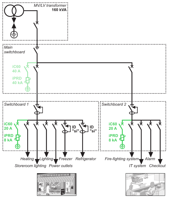
Solutions and schematic diagram
• The surge arrester selection guide has made it possible to determine the precise value of the surge arrester at the incoming end of the installation and that of the associated disconnection circuit breaker.
• As the sensitive devices (Uimp < 1.5 kV) are located more than 10m from the incoming protection device, the fine protection surge arresters must be installed as close as possible to the loads.
•To ensure better continuity of service for cold room areas:
∙ “si” type residual current circuit breakers will be used to avoid nuisance tripping caused by the rise in earth potential as the lightning wave passes through.
• For protection against atmospheric overvoltages:
∙ install a surge arrester in the main switchboard
∙ install a fine protection surge arrester in each switchboard (1 and 2) supplying the sensitive devices situated more than 10m from the incoming surge arrester
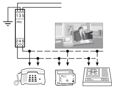
∙ install a surge arrester on the telecommunications network to protect the devices supplied, for example fire alarms, modems, telephones, faxes.
Cabling recommendations
• Ensure the equipotentiality of the earth terminations of the building.
• Reduce the looped power supply cable areas.
Installation recommendations
• Install a surge arrester, Imax = 40 kA (8/20 µs) and a iC60 disconnection circuit breaker rated at 40 A.
• Install fine protection surge arresters, Imax = 8 kA (8/20 µs) and the associated iC60 disconnection circuit breakers rated at 10 A
SPD for photovoltaic applications
Overvoltage may occur in electrical installations for various reasons. It may be caused by:
• The distribution network as a result of lightning or any work carried out.
• Lightning strikes (nearby or on buildings and PV installations, or on lightning conductors).
• Variations in the electrical field due to lightning.
Like all outdoor structures, PV installations are exposed to the risk of lightning which varies from region to region. Preventive and arrest systems and devices should be in place.
Protection by equipotential bonding
The first safeguard to put in place is a medium (conductor) that ensures equipotential bonding between all the conductive parts of a PV installation.
The aim is to bond all grounded conductors and metal parts and so create equal potential at all points in the installed system.
Protection by surge protection devices (SPDs)
SPDs are particularly important to protect sensitive electrical equipments like AC/DC Inverter, monitoring devices and PV modules, but also other sensitive equipments powered by the 230 VAC electrical distribution network. The following method of risk assessment is based on the evaluation of the critical length Lcrit and its comparison with L the cumulative length of the d.c. lines.
SPD protection is required if L ≥ Lcrit .
Lcrit depends on the type of PV installation and is calculated as the following table (Fig. J47) sets out:

L is the sum of:
• the sum of distances between the inverter(s) and the junction box(es), taking into account that the lengths of cable located in the same conduit are counted only once, and
• the sum of distances between the junction box and the connection points of the photovoltaic modules forming the string, taking into account that the lengths of cable located in the same conduit are counted only once.
Ng is arc lightning density (number of strikes/km2/year).
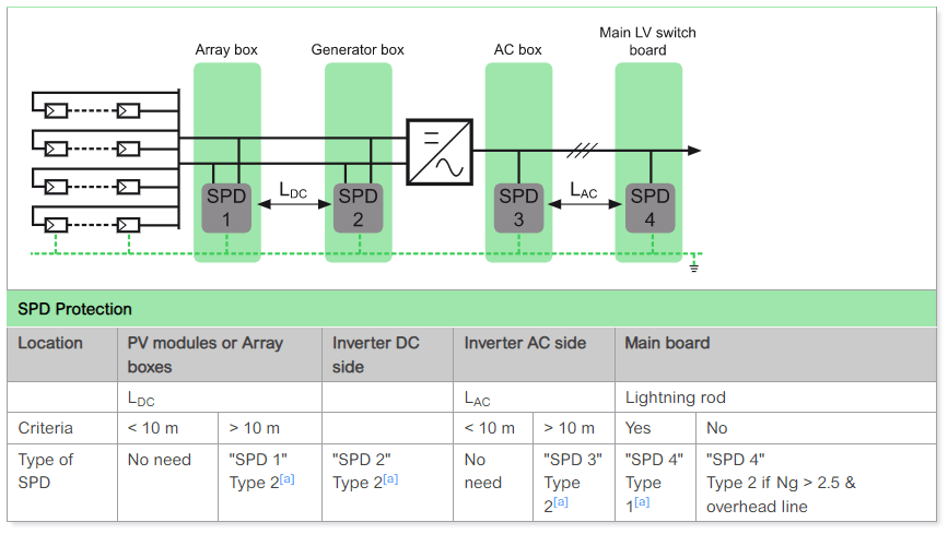
a. ^1 2 3 4 Type 1 separation distance according to EN 62305 is not observed.
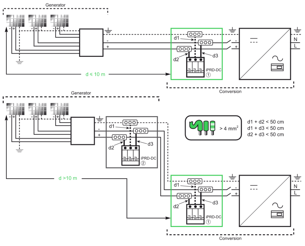
Installing an SPD
The number and location of SPDs on the DC side depend on the length of the cables between the solar panels and inverter. The SPD should be installed in the vicinity of the inverter if the length is less than 10 metres. If it is greater than 10 metres, a second SPD is necessary and should be located in the box close to the solar panel, the first one is located in the inverter area.
To be efficient, SPD connection cables to the L+ / L- network and between the SPD’s earth terminal block and ground busbar must be as short as possible – less than 2.5 metres (d1+d2<50 cm).
Safe and reliable photovoltaic energy generation
Depending on the distance between the “generator” part and the “conversion” part, it may be necessary to install two surge arresters or more, to ensure protection of each of the two parts.
Source URL: https://www.electrical-installation.org/enwiki/Surge_protection_Application_examples
