Published by 1. Ali Boukerche1, 2. Salima Lekhchine1, 3. Tahar Bahi2, Department of Mechanical Engineering, Faculty of technology, University of 20 August 1955, LGMM Laboratory, Skikda, Algeria (1), Department of Electrical Engineering,Faculty of technology, Badji Mokhtar University, Laboratory (LASA) , Annaba, Algeria (2) E-mail: a.boukerche@univ-skikda.dz
Abstract. At present, energy saving and renewable energies represent one of the most important axes of sientific research. One of these renewable energies is solar energy, which has two aspects: solar thermic and solar photovoltaic; this energy is highly coveted due to its availability, but the cost of this energy remains very high, specially for autonomous installations where there are storage batteries. the aim of this work is to minimise the invisible cost of storage and to promote energy saving using a connected network energy management system controlled by fuzzy logic.. There are several types of storage batteries, including batteries that are less expensive in terms of storage capacity and price (Wh/Price), such as OPZS batteries, but they cannot be used for a single consumer because their capacity is very large. In our work, we propose a collective storage structure between multiple variable loads, and each load is equipped with a photovoltaic generator that supplies the same storage bus. Fuzzy logic is used to collect information on the behaviour of loads, in other words the consumers, their compliance with the consumption instructions set in advance, as well as the degree of contribution to recharging the collective storage bus. Using mathlab simulink, we have performed a simulation of the proposed system. The result is that the program classifies the consumers and gives them a quantity of energy from the storage bus according to their class, a quantity that can be estimated using fuzzy logic. This approach can be used in a number of different ways, either by the electricity network distributors by installing collective storage buses in each utility, with multiple benefits such as the use of the storage bus as a back-up source in the event of a network failure to ensure continuity of service, energy savings, because consumers will try to save as much energy as possible in order to have a good rating and benefit from more energy in unfavourable weather conditions. It will also enable the electricity distributor to have a more smart and better-controlled grid, because consumers will respect hourly power consumption thresholds to have a better rating at all times instead of varying consumption rates on an hourly basis, as many suppliers do, to avoid consumption peaks that cause problems on the electricity network, such as voltage drops. Or co-location in a collective storage bus for off-grid installations to minimise the investment cost of the storage bus and be more respectful of the environment.
Streszczenie. Obecnie oszczędzanie energii i odnawialne źródła energii stanowią jedną z najważniejszych osi badań naukowych. Jedną z tych odnawialnych energii jest energia słoneczna, która ma dwa aspekty: słoneczną energię cieplną i słoneczną energię fotowoltaiczną; energia ta jest bardzo pożądana ze względu na jej dostępność, ale koszt tej energii pozostaje bardzo wysoki, szczególnie w przypadku autonomicznych instalacji, w których znajdują się akumulatory. Celem tej pracy jest zminimalizowanie niewidocznych kosztów magazynowania i promowanie oszczędzania energii przy użyciu połączonego sieciowego systemu zarządzania energią kontrolowanego przez logikę rozmytą. Istnieje kilka rodzajów akumulatorów, w tym akumulatory, które są tańsze pod względem pojemności i ceny (Wh / Cena), takie jak akumulatory OPZS, ale nie można ich używać dla pojedynczego konsumenta, ponieważ ich pojemność jest bardzo duża. W naszej pracy proponujemy zbiorczą strukturę magazynowania między wieloma zmiennymi obciążeniami, a każde obciążenie jest wyposażone w generator fotowoltaiczny, który zasila tę samą magistralę magazynową. Logika rozmyta jest wykorzystywana do zbierania informacji na temat zachowania obciążeń, innymi słowy konsumentów, ich zgodności z instrukcjami zużycia ustalonymi z wyprzedzeniem, a także stopnia wkładu w ładowanie zbiorczej magistrali magazynowej. Korzystając z programu Mathlab Simulink, przeprowadziliśmy symulację proponowanego systemu. W rezultacie program klasyfikuje konsumentów i daje im ilość energii z magistrali magazynowej zgodnie z ich klasą, ilość, którą można oszacować (Zalecenia dotyczące struktury i sterowania rozmytego wspólnego systemu magazynowania pomiędzy autonomicznymi systemami fotowoltaicznymi)
Keywords: Photovoltaic,MPPT,Storage,Battery,Fuzzy logic,Energy management.
Słowa kluczowe: Fotowoltaika, MPPT, magazynowanie, akumulator, logika rozmyta, zarządzanie energią.
Introduction
Nowadays, the ever-increasing need for electrical energy throughout the world requires an increase in the production of electrical energy in order to satisfy this need and therefore requires the establishment of a significant number of power stations.
Indeed, to satisfy the growing demand for electrical energy, several types of conventional power plants are installed [1-3]. These stations use as raw material the fossil energies which are known as not-renewable, they are polluting and have a negative impact on the environment, and are also being depleted [4,5]. This goes against the current standards and issues defined for the environment. To overcome these problems, governments have adopted as an indispensable solution the promotion of electric energy production facilities based on renewable resources such as solar energy, wind energy, biomass etc…[6-8]. However, solar energy is the most used because of its wide availability. It is divided into two types, the first type being solar thermal, a partly chemical process generally used in high power plants (thermo-solar power station) and the second type is the photovoltaic solar energy which can be used for large as well as for small powers [9,10].
In this work we are interested to design an optimal structure and to propose the power management of solar photovoltaic installations not connected to the distribution network (autonomous) equipped with a common storage system. The storage system consists of a set of lithium batteries with deep discharge of voltage 2V particularly batteries OPZS: O: Ortsfest (stationary), PZ : PanZerplatte (tubular plate) and S : Flüssig (flooded) which are designed on the basis of an electrical energy storage technology particularly adapted to photovoltaic solar systems [11]. These batteries are made of positive and negative lead plates, separated by separators and immersed in a liquid electrolyte. In contrast to other types of batteries, OPZS batteries have the advantage of being transparent, which makes it easy to see the condition of the plates and electrolyte [12]. They have a relatively long life, which makes them an interesting choice for applications requiring long-term storage of the renewable energy produced. However, to obtain 24V or 48V storage bus, several of these batteries are needed, which is appropriate for large load. They are used as an intermediary to all production facilities in order to optimize the investment on storage bus and promote the saving of electrical energy. Nevertheless, to ensure their optimal use, a large load or several medium loads are required. This is the subject of our work as well as the promotion of economy of electrical energy.
Structure and modeling
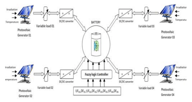
Structure In this work a new structure of an electrical network consisting of a collective storage bus between several isolated sites with a photovoltaic generator each one is proposed. The charging and discharging system of each installation is based on a Buck-boost converter and a proportional integral (PI) controller. The systems will be interconnected using a control system based on fuzzy logic that will take into consideration the energy delivered by each system to the storage bus as well as the consumption mode of each system in order to incite the users to better consume and respect the energy consumption thresholds.
Using MatLab/Simulink software, we have developed a system composed of 4 photovoltaic generators two of them composed of five of 215Wp panels which are the GPV1 and GPV4, 4 panels of the same type for GPV2 and 3 panels for GPV3 all equipped with a Boost converter with a Maximal Power Point Tracking (MPPT) incremental control, each one of them powering a variable load with different variations for each load, the set of loads connected to storage bus 120Ah- 24V controlled by a controller based on fuzzy logic as shown in the Fig.1.
Modeling Photovoltaic cell model
The photovoltaic cell is the basic element of a solar panel and consists of a current generator and a diode, as well as two resistors – one in series (Rs) and one in parallel (Rsh). The equivalent electrical circuit of this cell is shown in the Fig.2.and considered this figure we can deduce the expression of the current [13-15]:
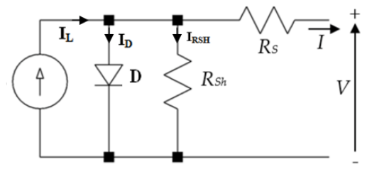
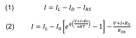
Where, I0 (A): diode saturation current; K: constant of Boltzmann (1, 380649×10-23 m2 kg s-2 K-1); q: charge of the electron; T: temperature; n: factor of diode junction; IL (A): short-circuit current; ID (A): current through the diode; IRsh (A) : current through the shunt resistor.
DC-DC converters
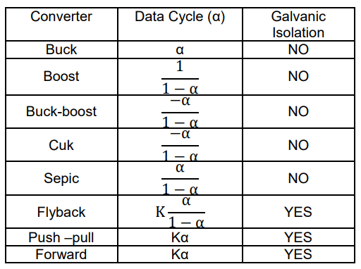
A DC/DC converter is an electronic device that converts a DC voltage from one power source to another DC voltage of a different level, usually using a pulse width modulation (PWM) technique [16,17]. There are several types of DC/DC converters, each with different characteristics and advantages, such as Buck converters it converts a high input voltage to a lower output voltage, Boost Converter: it converts a lower input voltage to a higher output voltage, and the Buck-Boost Converters it can convert a high input voltage to a lower output voltage or convert a lower input voltage to a higher output voltage. The table 1 shows the most frequently used DC/DC converter models [18-20].
Table 1. Converters DC/DC
Boost converter model
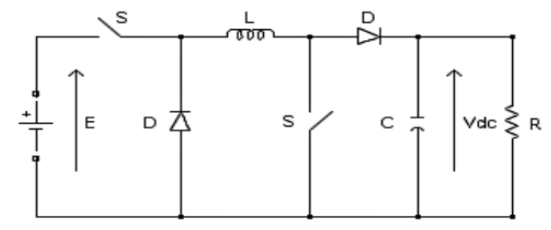
The mathematical model of the boost converter is derived by applying Kirchhoff’s laws to the basic schematic of the converter, as shown in Fig.3 and taking into account the mode of operation and the state of the S-switch. In other words, the principles of conservation of energy and electrical load are used to describe the behavior of the boost converter under different operating conditions as a function of parameters such as input voltage, connected load, and the switching frequency of the S switch [21].
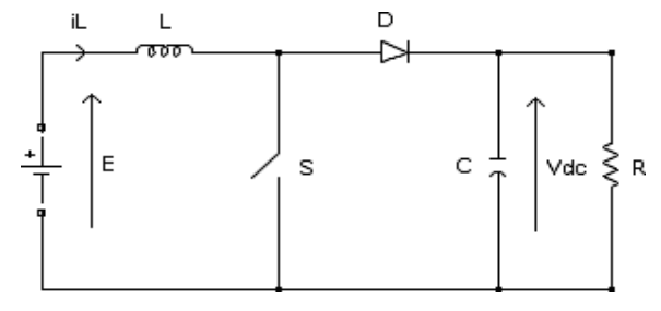
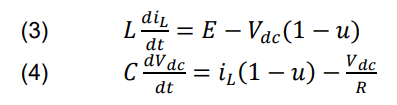
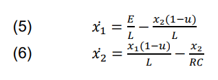
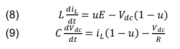
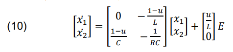
The dynamic equations of the boost converter are derived for the current in the inductor and the voltage across the capacitor in the continuous conduction regime, where IL is the current in the inductor L, E is the input voltage, Vdc is the output voltage, and U is the control. For x1 =IL and x= Vdc then the equations of state become:
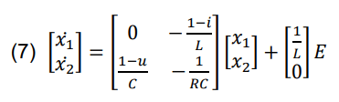
The equation of state of the boost converter thus becomes:
Buck-boost converter model
To present the functioning of a converter of this type in the form of mathematical equations, it is necessary to consider the state of the switch S, as shown in the Fig.4 When the switch is in the ON position, the time Ton during which it is conducting is equal to α times the switching period Ts. During this phase, the energy stored in the circuit inductor increases. On the other hand, when the switch is OFF, the time Toff during which it is not conducting is equal to (1-α) times the switching period Ts. During this phase, the energy stored in the inductor is transferred to the capacitance and the load connected to the converter [22].
The equation of state of the buck boost converter gives:
Incremental MPPT technique
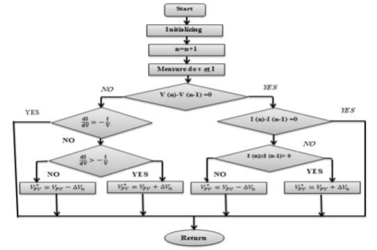
This technique requires the use of two sensors to measure the output voltage and current [23-25]. It uses the derivative of current with respect to voltage (dI/dV) to estimate the derivative of power with respect to voltage (dP/dV). When dI/dV equals (-I/V), the algorithm detects that the maximum power point (MPP) has been reached, and it then stops to return the appropriate operating voltage value for the Maximum power point. Figure 5 shows the algorithm for the incremental technique to track the maximum power bridge.
Charge controller
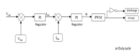
The voltage control system is a technique commonly used in photovoltaic systems to charge the batteries by imposing a voltage set point. Using a Buck-Boost DC/DC converter, this technique is very efficient because it allows to maintain the battery voltage at an optimal level according to the state of charge or discharge, which prolongs its life [26].The operation of the imposed voltage charge controller is simple the system follows the imposed voltage set point and adjusts the current according to the load requirements. In other words, the current is adapted in real time to meet the requirements of the load and the availability of the energy delivered by the PV array.
Figure 6 illustrates this process the voltage is controlled to remain constant, while the current varies according to the demands of the load. This technique maximizes the battery’s charging efficiency while protecting it from over- or under-charging, thereby significantly extending its life.
2.2.5. fuzzy logic controller
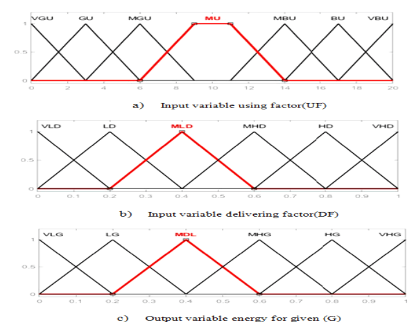
Fuzzy logic is a method of information treatment that makes it possible to model complex systems by using fuzzy sets and variables that can take gradual values. This technique is largely used in electrical engineering for the control of control systems, the control of electric motors, robotics and image and signal processing systems [27-29]. Several fuzzy logic source management projects have been proposed by classification, as in [30] In our case we are going to use it to manage the quantity of energy delivered by the storage batteries according to the acquired data of the system, the input parameters of our fuzzy controller are the using factor that varies from 0 to 20 from very good user to very bad user and the second parameter and the giving factor that varies from 0 to 100% of the delivered energy according to the rules mentioned in the Table 2. To assure the good functioning and the longevity of the battery the energy that is delivered between the four systems will be limited to a threshold of 30% of the battery autonomy to avoid the deep discharge harmful to the battery, the rules established for the fuzzy system are as in Table 2.
Table 2. Fuzzy log
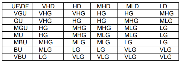
We will have the amount of energy to be delivered for each user at night or in bad weather and even in the case of pane. Figure 7 shows the conversion of the numerical input variables into linguistic variables. The abbreviations used for the using factor (UF) are VGU,GU,MGU,MU,MBU,BU and VBU are relative to very good user, good user, middle good user, middle bad user, bad user and very bad user this variable of between vary sell the respect of the consumer to the consumptions instructions.
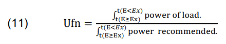
With the condition If t=0 UFn=Cn else UFn= Cn/t
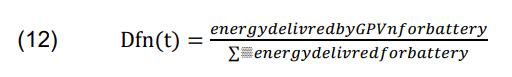
For the second input variable delivering factor (DF) we have VLD, LD, MLD, MHD, HD and VHD for very low deliverer, low deliverer, middle low deliverer, middle high deliverer, high deliverer and very high deliverer this parameter varies according to the ratio between the energy delivered by a GPVn system to the storage bus and some of the energy delivered to the storage bus by all the photovoltaic generators.
For t ∈ [(𝐸≥𝐸𝑥);(𝐸<𝐸𝑥)]
We note that Ex is the irradiation sufficient for the availability of photovoltaic energy in our case we have taken 100w/m², the data processing is done according to the program in Fig.8.
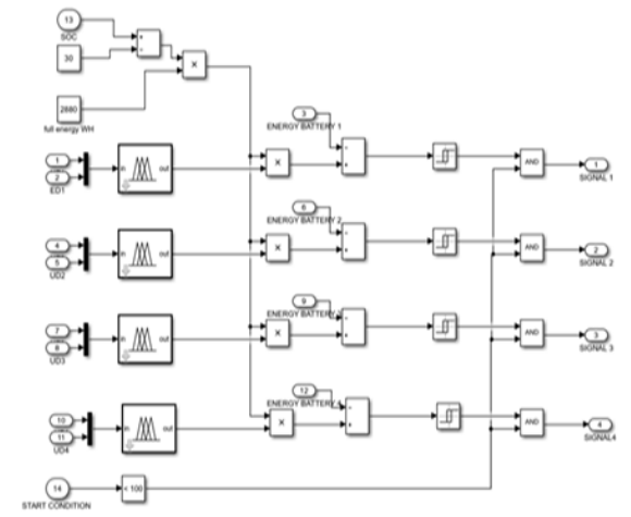
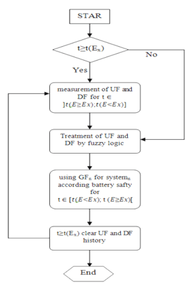
The system operates according to the flow diagram in the figure Fig.9 at time t≥t(Ex) for t(Ex) is the time when the photovoltaic system receives a large enough irradiation to develop a considerable power in our case we took E=100w/m² the data calculation is done during the period t ∈ ]𝑡(𝐸≥𝐸𝑥); 𝑡(𝐸<𝐸𝑥)] equivalent to one day of production to then deliver the energy from the storage bus at period t ∈ [𝑡(𝐸<𝐸𝑥); t (𝐸≥𝐸𝑥)] according to the giving factor estimated by the fuzzy algorithm at the end of the cycle the acquired data Uf and Df will be deleted to make place for the new data. Figure 9 shows the detailed operation of the controller for a simulation period relating to a normal day.
Simulation result and discussion
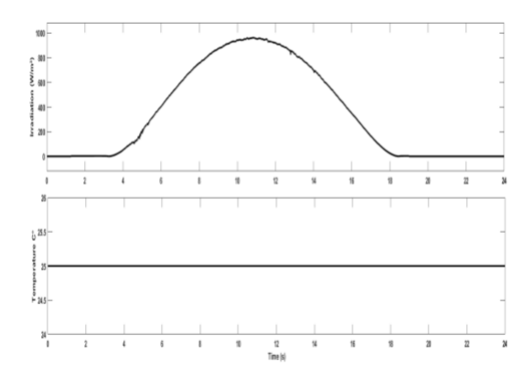
The proposed structure and control was developed in Matlab/Simulink to analyze the performance of our approach and its validation under different operating profiles inspired by real cases considering a constant temperature of 25°C and a variable irradiation profile as shown in the Fig.10.
The time of data collection is from t=4.2s corresponding to an ‘irradiation E≥100W/m² which is proportional to the dawn and the distribution of stored energy is done from the moment t=17.5 or the irradiation E<100W/m² which is proportional to the twilight two simulation phase one with the fuzzy controller deactivated in second with the fuzzy controller activated.
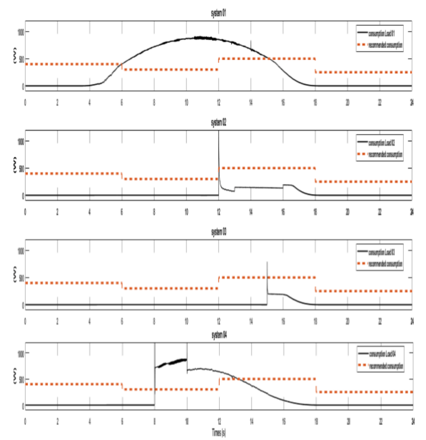
However, under the effect of climatic profiles (constant temperature and variable irradiation) of the figure 10, the evolution of the recommended power as well as the powers actually consumed by each load as a function of time, respectively shown by the dashed lines and the solid lines of the Figure 11.
With the knowledge of the evolution of the powers consumed by the various loads as well as the set point of consumption according to the laws of calculation establishes the factor of use Uf and the factor of donation Df which reflect respectively the respect of each load with regard to the set point of consumption and the quantity of energy delivered to the bus of storage by each system compared to the totality of the energy received by the bus of storage, the Figures 12 and 13 illustrate these two factors
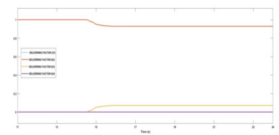
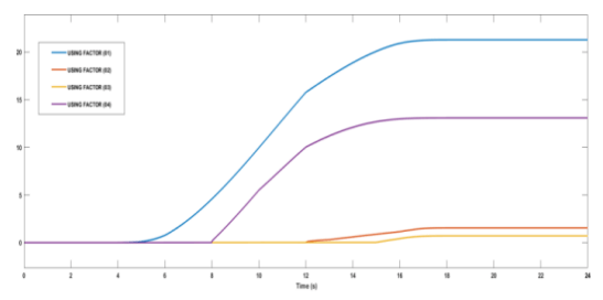
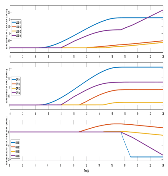
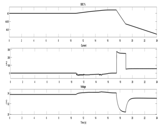
Figure 14 shows the energy delivered by the photovoltaic generator, the consumption of the loads and the energy delivered to the storage bus of the four systems respectively. Figure 15 shows the state of charge of the battery (soc) its current and voltage without application of the fuzzy controller, We notice that the battery was charged from t=11s to t=16s the period where there was an excess of energy production. We also notice that the GPV 02 and 03 are the most implied in terms of charge of the battery having a good factor of Delivering (Df) while respecting the consumption The GPVs 01 and 04 did not contribute practically to the battery charge, however, in terms of respecting the consumption set point, the load four is higher than the load 01 (Uf04>Uf01) as shown in figures 11 and 12.
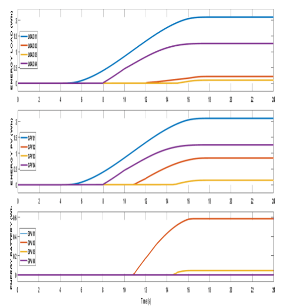
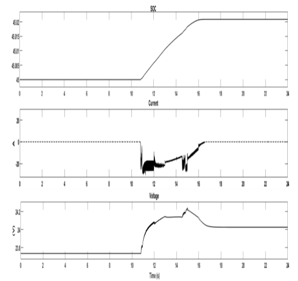
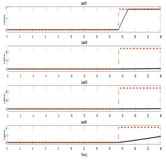
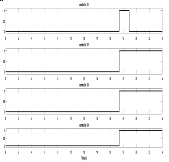
Figure 16 shows the energy delivered by the PV array, the consumption of the l loads and the energy delivered to the storage bus of the four systems but this time applying the fuzzy logic controller. Figure 17 shows the thresholds set by the fuzzy system and the consumption of each load of the storage bus. It can be seen that load 01 has been excluded at t=19s because it has a bad Uf and Df factor and it requires a large current as shown in Fig.19.
Conclusion
At the end of this work, it was proven that it is possible to make photovoltaic installations with storage, which are classified among the most expensive photovoltaic installations, more profitable by investing in a collective storage bus while inciting consumers to respect consumption thresholds to promote energy saving and ensure a good continuity of service whatever the climatic conditions to which the installations are solicited and also in the event of unexpected defect occurring in one of the installations. Furthermore, the proposed structure encourages users to save electrical energy and allows suppliers to better manage their facilities by prescribing energy consumption guidelines to users and can also be designed for a more complex system.
REFERENCES
1. MD. LEONARD, E.E.MICHAELIDES and D. MICHAELIDES, Energy storage needs for the substitution of fossil fuel power plants with renewables. Renewable Energy,145, pp. 951-962 (2020).doi: https://doi.org/10.1016/j.renene.2019.06.066
2. SO. AMROUCHE, D. REKIOUA, T. REKIOUA and al. Overview of energy storage in renewable energy systems. International journal of hydrogen energy, 41, 45, pp 20914-20927 (2016).doi: https://doi.org/10.1016/j.ijhydene.2016.06.243
3. M. UMAR, X. JI, D. KIRIKKALELI and al. The imperativeness of environmental quality in the United States transportation sector amidst biomass-fossil energy consumption and growth. Journal of Cleaner Production, 285, pp.124863 (2021).doi: https://doi.org/10.1016/j.jclepro.2020.124863
4. F. GUANG, Electrical energy efficiency of China and its influencing factors. Environmental Science and Pollution Research, 27, 26, pp. 32829-32841 (2020). doi: https://doi.org/10.1007/s11356-020-09486-6
5. Ayat Y., Badoud A.E., Mekhilef S., Gassab S. Energy management based on a fuzzy controller of a photovoltaic/fuel cell/Li-ion battery/supercapacitor for unpredictable, fluctuating, high-dynamic three-phase AC load. Electrical Engineering & Electromechanics, 2023, no. 3, pp. 66-75. doi: https://doi.org/10.20998/2074-272X.2023.3.10:
6. A. SHARIF, M. BHATTACHARYA, S. AFSHAN and al. Disaggregated renewable energy sources in mitigating CO2 emissions: new evidence from the USA using quantile regressions. Environmental Science and Pollution Research,28 ,41, pp.57582-57601 (2021). doi: https://doi.org/10.1007/s11356-021-13829-2
7. SK. BHATIA, AK. PALAI, A. KUMAR, and al. Trends in renewable energy production employing biomass-based biochar. Bioresource Technology,340, pp. 125644 ( 2021). doi: https://doi.org/10.1016/j.biortech.2021.125644
8. Ali Moussa M., Derrouazin A., Latroch M., Aillerie M. A hybrid renewable energy production system using a smart controller based on fuzzy logic. Electrical Engineering & Electromechanics, 2022, no. 3, pp. 46-50. doi: https://doi.org/10.20998/2074-272X.2022.3.07 PRZEGLĄD ELEKTROTECHNICZNY, ISSN 0033-2097, R. 100 NR 6/2024 263
9. A. BORETTI, Integration of solar thermal and photovoltaic, wind, and battery energy storage through AI in NEOM city. Energy and AI, 3,pp.100038(2021). doi:https://doi.org/10.1016/j.egyai.2020.100038
10. U. EICKER, A. COLMENAR-SANTOS, L. TERAN and al. Economic evaluation of solar thermal and photovoltaic cooling systems through simulation in different climatic conditions: An analysis in three different cities in Europe. Energy and Buildings,70, pp. 207-223 (2014). doi: https://doi.org/10.1016/j.enbuild.2013.11.061
11. R. DUFO-LÓPEZ, T. CORTÉS-ARCOS, JS. ARTAL-SEVIL and al. Comparison of lead-acid and li-ion batteries lifetime prediction models in stand-alone photovoltaic systems. Applied Sciences,11, 3, pp. 1099 (2021). doi: https://doi.org/10.3390/app11031099
12. A. KARAFİL, H. ÖZBAY, Design of Stand-Alone PV System on a Farm House in Bilecik City, Turkey. El-Cezeri,5,3,pp.909-916 (2018). doi: https://doi.org/10.31202/ecjse.352826
13. Latreche S., Khenfer A., Khemliche M. Sensors placement for the faults detection and isolation based on bridge linked configuration of photovoltaic array. Electrical Engineering & Electromechanics, 2022, no. 5, pp. 41-46. doi: https://doi.org/10.20998/2074-272X.2022.5.07
14. AM. SHAHEEN, RA. EL-SEHEIMY, G. XIONG and al. Parameter identification of solar photovoltaic cell and module models via supply demand optimizer. Ain Shams Engineering Journal,13,4, pp. 101705 (2022). doi: https://doi.org/10.1016/j.asej.2022.101705
15. Y. MAHMOUD et E. EL-SAADANY, A photovoltaic model with reduced computational time. IEEE transactions on industrial electronics,62,6, pp. 3534-3544 (2014). doi: 10.1109/TIE.2014.2375275
16. S. KAPAT and P. KREIN. A tutorial and review discussion of modulation, control and tuning of high-performance dc-dc converters based on small-signal and large-signal approaches. IEEE Open Journal of Power Electronics, 1, pp. 339-371 (2020). doi: https://doi.org/10.1109/OJPEL.2020.3018311
17. H. TARZAMNI, F. ESMAEELNIA, F. TAHAMI and al, Reliability assessment of conventional isolated PWM DC-DC converters. IEEE Access,9, pp. 46191-46200 (2021). doi: https://doi.org/10.1109/ACCESS.2021.3067935
18. B. ZHU, HU, L. Shishi, Guanghui, and al, Low-voltage stress buck-boost converter with a high-voltage conversion gain. IEEE Access, 8, pp. 95188-95196 (2020). doi: 10.1109/ACCESS.2020.2995889
19. A. RAJAVEL and P. RATHINA, Fuzzy logic controller-based boost and buck-boost converter for maximum power point tracking in solar system. Transactions of the Institute of Measurement and Control,43, 4, pp. 945-957 (2021). doi: https://doi.org/10.1177/0142331220938211
20. B. CHANDRASEKAR, CH. NALLAPERUMAL, S. PADMANABAN and al, Non-isolated high-gain triple port DC– DC buck-boost converter with positive output voltage for photovoltaicapplications. IEEEAccess,8,pp.113649-113666, (2020). doi: 10.1109/ACCESS.2020.3003192
21. Tahar, Benaissa, Mahi Djillali, and Halbaoui Khaled. “Maximum Power Point Tracking under simplified sliding mode control based DC-DC boost converters.” Przeglad Elektrotechniczny 97.7 (2021). doi:10.15199/48.2021.07.12
22. N. OBEIDI, M. KERMADI, B. BELMADAN and al, A current sensorless control of buck-boost converter for maximum power point tracking in photovoltaic applications. Energies,15,20,pp. 7811 (2022). doi: https://doi.org/10.3390/en15207811
23. HAMOODI, Ali N., Safwan A. HAMOODI, and Farah I. HAMEEDI. “Enhancing the Solar PV Plant Based on Incremental Optimization Algorithm.” Przeglad Elektrotechniczny 2023.10 (2023).. doi:10.15199/48.2023.10.35
24. RB. BOLLIPO,S. MIKKILI and K. BONTHAGORLA, Hybrid, optimal, intelligent and classical PV MPPT techniques: A review. CSEE Journal of Power and Energy Systems,7,1, pp.9- 33 (2020). doi: 10.17775/CSEEJPES.2019.02720
25. I. OWUSU-NYARKO, MA.ELGENEDY, I. ABDELSALAM and al. Modified variable step-size incremental conductance MPPT technique for photovoltaic systems. Electronics,10,19,pp. 2331(2021). doi: https://doi.org/10.3390/electronics10192331
26. Jusoh, Mohd Afifi, Muhamad Zalani Daud, and Mohd Zamri Ibrahim. “Fuzzy logic-based control strategy for hourly power dispatch of grid-connected photovoltaic with hybrid energy storage.” Przeglad Elektrotechniczny 98.1 (2022). doi: https://doi.org/ 10.15199/48.2022.01.02
27. ZOUGGARET, Abdelhak, et al. “An Efficient Fuel Cell Maximum Power Point Tracker based on an Adaptive Neural Fuzzy Inference System.” Przeglad Elektrotechniczny 99.2 (2023). doi:10.15199/48.2023.02.23
28. M. KOTB, M. ELMORSHEDY, H. SALAMA and al. Enriching the stability of solar/wind DC microgrids using battery and superconducting magnetic energy storage based fuzzy logic control. Journal of Energy Storage,45, pp.103751 (2022). doi: https://doi.org/10.1016/j.est.2021.103751
29. Z. ROUMILA, D. REKIOUA, et T. REKIOUA, Energy management based fuzzy logic controller of hybrid system wind/photovoltaic/diesel with storage battery. International Journal of Hydrogen Energy,42,30, pp.19525-19535 (2017). doi: https://doi.org/10.3390/en16052286
Source & Publisher Item Identifier: PRZEGLĄD ELEKTROTECHNICZNY, ISSN 0033-2097, R. 100 NR 6/2024. doi:10.15199/48.2024.06.54
