Published by Krzysztof OLESIAK, Czestochowa University of Technology ORCID: 0000-0003-4552-7810
Abstract. The paper presents a method of measuring power consumed by an industrial robot in a single phase system. A computer-based measurement set was constructed, consisting of special purpose voltage and current converters and a PC with a multi-channel measuring card. Measurements were conducted and time curves were recorded for the supply voltage and current of the robot under dynamic states at prescribed trajectories. The software DasyLab was used to plot time waveforms, to obtain power values and to record data. The power consumed by the robot was analyzed for variations in the kind of movement at prescribed trajectories.
Streszczenie. W artykule zaprezentowano koncepcję pomiarów mocy pobieranej w układzie jednofazowym przez robota przemysłowego. Komputerowy układ pomiarowy wykonano przy zastosowaniu specjalistycznych przetworników napięcia i prądu oraz komputera PC z wielokanałową kartą pomiarową. Przeprowadzono badania pomiarowe i zarejestrowano przebiegi czasowe napięcia i prądu zasilania robota dla stanów dynamicznych przy zadanych trajektoriach ruchu. Do rejestracji przebiegów czasowych, wyznaczania mocy oraz zapisu danych w czasie rzeczywistym zastosowano oprogramowanie DasyLab. Przeprowadzono analizę mocy pobieranej przez robota przemysłowego przy zmianie rodzaju ruchu dla zadanych trajektorii ruchu. (Pomiary mocy pobieranej przez robota przemysłowego w stanach dynamicznych).
Keywords: industrial robot, movement trajectory, power measurement, computer measuring system.
Słowa kluczowe: robot przemysłowy, trajektoria ruchu, pomiar mocy, komputerowy system pomiarowy.
Introduction
Multiaxial robots with electric drives appeared in industry in the 1970s. They were more advanced versions of earlier robots powered by hydraulic or electrohydraulic drives used in the 1950s and 1960s [2, 3].
The development of power semiconductor systems and microprocessor control systems contributed to increase in the sales of electric drive robots and gradually expanded their applications. Nowadays, industrial robots are used in manufacturing processes requiring numerous repetitions of the same action with high precision and speed. The tasks performed by robots can be divided into four main categories according to function: i) joining components, i.e. fusion welding, pressure welding and soldering ii) moving components, i.e. sorting, packaging and arranging objects, iii) tasks involving a change in the size of an object, i.e. drilling, milling and machining, iv) tasks resulting in altering surface parameters of components, such as chemical degreasing and spray painting [2, 5, 8, 10].
Industrial robots consume electric power, the value of which depends on the nominal parameters, the movement trajectory and the load applied to the effector. A general construction schema of a controller in a multiaxial robot with an electric drive consists of a rectifier circuit, a DC circuit, converters powering the motors of the mechanical manipulator and a microprocessor control, and a programming unit. The movement trajectory is programmed by means of a manual touch programmer connected to the controller. The construction of the controller indicates that the unit is a non-linear power receiver [11, 15].
Developing the power measurement tool and method for industrial robots required the analysis of measurement methodology for converter drives, non-linear circuits, and also measurements of non-electric quantities. It was also necessary to take into consideration issues related to simulation models of power converters and converter drives [12, 13, 14].
The computer-based power measurement system
The industrial robot under scrutiny is powered by standard single-phase voltage. The computer-based power measurement system consists of two measuring transducers, a special-purpose measuring card and a PC. The power circuit is galvanically isolated from the measuring circuit by means of measuring transducers manufactured by LEM. The transducer applied in the power circuit is LA55-P, whereas the one in the voltage circuit is LA55-P. The parameters of the measuring transducers are specified in Table 1.
Table 1. The parameters of the measuring transducers [9
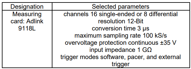
The measuring transducers transform the current and the voltage, respectively, into voltage signals of identical shape within the range from -5V to +5V. These voltage signals are connected through an external module to the measuring card Adlink 9118L installed in the PC. The measuring card has a 12-bit A/D converter with a maximal sampling frequency of 100 kHz and with 8 bipolar channels for simultaneous registration of the waveforms in the domain of time. The parameters of the measuring card are specified in Table 2.
Table 2. The parameters of the measuring card [4]
The PC was equipped with the DasyLab software for reading, registration and visualization of signals from the measuring card Adlink. The signals can be measured for prescribed trajectories of the industrial robot’s TCP (Tool Center Point). Individual trajectories are programmed by means of a manual touch programmer, connected to the robot controller. Fig. 1 below presents a block diagram of the computer-based measuring system.
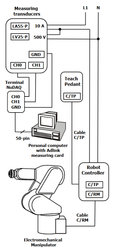
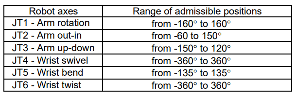
The electromechanical manipulator’s arm takes a position depending on the parameters prescribed for the individual axes. The range of admissible positions of the Kawasaki robot axes is presented in Table 3.
Table 3. The range of admissible positions of the Kawasaki FS03N robot axes [7]
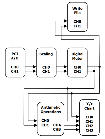
The signals received from the voltage and current converters are read by the channels of the measuring card, and subsequently processed and saved by the DasyLab software. The processing of the signals consists of the following stages: calibrating the voltage and current, reading and visualizing by the digital meter module, calculating the sought values according to the given dependencies, and presenting the results in the form of waveforms. The measurement results are recorded in real time as per the affordances of the DasyLab software. The block diagram of the system for processing the measuring signals is presented in Fig. 2.
The power of the non-linear receiver
According to the classic definition of power, the active power of a receiver is [1, 6]:
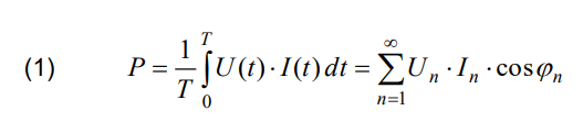
where: P – the active power, T – period of time function, U(t), I(t) – the waveforms of the phase voltage and the phase current, Un – effective value of n-th harmonic voltage, In – effective value of n-th harmonic current, n –harmonic order, φn – the phase shift angle between n-th harmonic voltage and n-th harmonic current.
The formula above has a general character and can be applied to receivers in which the current and voltage curves are deformed. In the case of the industrial robot under scrutiny, the supply voltage is sinusoidal, whereas the current is deformed. This means that the transfer of active power involves the first harmonic of the sinusoidal voltage and the first harmonic of the deformed current. The other current harmonics do not affect the transfer of the active power. The active power of the system can be therefore represented as:
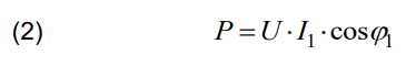
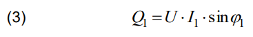
where: U – effective value of the sinusoidal phase voltage, I1 – effective value of the fundamental harmonic current, φ1 – the phase shift angle between the voltage and the fundamental harmonic current.
The phase shift between the sinusoidal supply voltage and the first current harmonic causes the receiver to receive reactive power Q1 equal to:
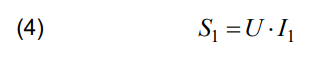
When the formulas for the active and reactive power are taken into account, it is possible to introduce a formula for the harmonic apparent power S1:
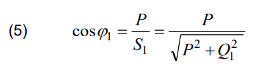
Thus, the phase shift coefficient of the fundamental harmonic becomes :
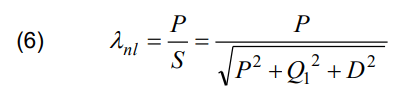
Higher harmonics of the distorted current are responsible for the occurrence of distortion reactive power D. This power is taken into account when the power factor λnl of the non-linear receiver is calculated by means of the following formula [1, 6]:
Results of the measurement study
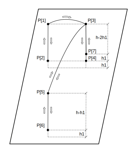
The study of the measurements involved registering the waveforms of the supply voltage and current in the domain of time for selected dynamic states of the industrial robot. The movement trajectory was set for moving two objects by means of a pneumatic effector. One object was moved from point P[2] to point P[4], and the other from point P[6] to P[7]. The lifting and lowering of the object involved linear movement, whereas the relocating of the object at a given height involved joint movement. The movement trajectory for the TCP is presented in Fig. 3.
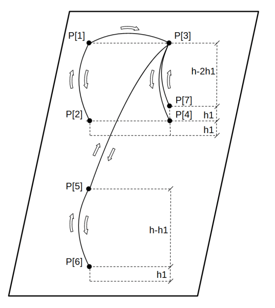
Applying a linear movement for lifting and lowering objects is a typical solution. When the robot is equipped with a pneumatic effector with height compensation, it is possible to apply joint movement instead, which reduces the time necessary for executing a given sequence of the movement. The movement trajectory of the TCP for the joint movement is presented in Fig. 4.
The power consumed by the robot at dynamic states was calculated by means of the DasyLab software. In the computational modules of the software mathematical functions determining the components of power were implemented. The results of the calculations are presented as waveforms in Fig. 5 and Fig. 6.
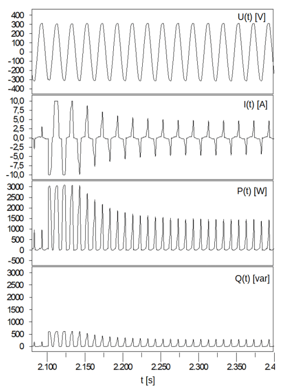
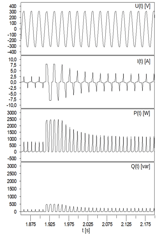
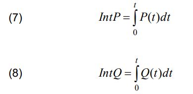
Integral factors were calculated for the active power and the reactive power, according to the following relations:
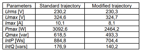
Time t=5s was assumed for the analyzed trajectories. In order to compare the obtained test results, selected parameters are presented in Table 4.
Table 4. Selected parameters for the standard and modified trajectory of the industrial robot’s TCP
Concluding remarks
The results of the measurements and analysis of the power consumed by an industrial robot for given movement trajectories indicate that the active power differs between the condition of linear movement and the condition of joint movement for lifting and lowering objects: in the joint movement condition both the active and reactive powers are lower. The difference occurs due to the mechanical construction of the robot manipulator, optimized for joint movement. It may be necessary, though, to apply the linear movement under some technological constraints, such as when the effector for moving objects is not height-compensated. Then the linear movement has to be applied for selected sections of the trajectory and the increase in the active and reactive fundamental harmonic power has to be taken into account.
The analysis of the power consumed for prescribed trajectories therefore indicates that applying joint movement has advantages over linear movement as long as there are no technological constraints which necessitate the linear movement at some sections of the trajectory. Reducing the active and reactive power consumption for executing given tasks reduces energy consumption for every cycle of the robot operation. Considering the fact that each cycle is repeated numerous times, the overall energy saving is significant.
REFERENCES
[1] Emanuel A. E., Power Definitions and the Physical Mechanism of Power Flow, Wiley-IEEE Press, 2010
[2] Hägele M., Nilsson K., Pires N., Bischoff R., Industrial robotics, Springer Handbook of Robotics, 2nd Edition, (2016), 1385-1421
[3] Hentout A., Maoudj A., Aouache M. A review of the literature on fuzzy-logic approaches for collision-free path planning of manipulator robots, Artificial Intelligence Review 56 (4), (2022), 3369-3444
[4] IOtech, DASYLab Data Acquisition System Laboratory – User Guide, version 10.0, IOtech Company, Cleveland, 2009
[5] Jakubiec B., Fuzzy Logic Controller for Robot Manipulator Control System. 2018 Applications of Electromagnetics in Modern Techniques and Medicine (PTZE), IEEE, New York, (2018), pp. 77-80
[6] Jeltsema D., Budeanu’s Concept of Reactive and Distortion Power Revisited, Przegląd Elektrotechniczny, 92 (2016), No. 4, 68-73
[7] Kawasaki Heavy Industries Ltd, Kawasaki Robot Controller D Series, AS Language Reference Manual, 2007
[8] Kim J., Kim S. R., Kim S. J., Kim D. H., A practical approach for minimum-time trajectory planning for industrial robots. Industrial Robot: An International Journal, 37(1), (2010), 51–61
[9] LEM: Industry Current & Voltage Transducers, Switzerland, Geneva, LEM International SA, 2013
[10] Mineo C., Pierce S. G., Nicholson P. I., Cooper I., Robotic path planning for non-destructive testing – A custom MATLAB toolbox approach, Robotics and Computer-Integrated Manufacturing, 37, Elsevier, (2016), 1-12
[11] Olesiak K., Analysis of the energy consumption by an industrial= robot for the angular movement of individual axes, Przegląd Elektrotechniczny, 94 (2018), No. 12, 218-221
[12] Popenda A., Modelling of BLDC motor energized by different converter systems, Przegląd Elektrotechniczny, 94 (2018), No.1, 81-84
[13] Popenda, A., Lis, M., Nowak, M., Blecharz, K., Mathematical modelling of drive system with an elastic coupling based on formal analogy between the transmission shaft and the electric transmission line, Energies, 13, no. 5 (2020), 1181
[14] Prauzner T., Prauzner K., Ptak P., Noga H., Migo P., Małodobry Z., Comparison of QEEG test results with regard to the environment, Journal of Physics: Conference Series 2408 (2022), 012011
[15] Tavares P., Lima J., Costa P., Double A* path planning for industrial manipulators, Advances in Intelligent Systems and Computing, 418, (2016), 119-130
Author: dr inż. Krzysztof Olesiak, Politechnika Częstochowska, Wydział Elektryczny, Katedra Automatyki, Elektrotechniki i Optoelektroniki, Al. Armii Krajowej 17, 42-200 Częstochowa, e-mail: krzysztof.olesiak@pcz.pl
Source & Publisher Item Identifier: PRZEGLĄD ELEKTROTECHNICZNY, ISSN 0033-2097, R. 101 NR 1/2025. doi:10.15199/48.2025.01.45
