Published by Konrad SEKLECKI, Leszek S. LITZBARSKI, Marek OLESZ, Emanuel GIFUNI, Grzegorz REDLARSKI, Jacek GROCHOWSKI
Abstract. The article describes recommendations related to the optimal selection of inverters for PV micro-installations. It presents different types of inverters used in PV installations depending on their type and power. Regardless of the case, attention should be paid to the maximum voltage and input current of the device. However, the appropriate quality of the inverter and its compliance with applicable regulations, as evidenced by appropriate certificates, are equally important. Undersizing the inverter in relation to the peak power of the PV installation results in its more efficient operation. Based on the analysis of real examples of PV micro-installations, it was found that in many cases there is a problem with the selection of appropriate inverters.
Streszczenie. Artykuł opisuje zalecenia związane z optymalnym doborem falowników do mikroinstalacji PV. Przedstawiono w nim różne rodzaje falowników stosowanych w instalacjach PV w zależności od ich typu i mocy. Niezależnie od przypadku należy zwrócić uwagę na maksymalne napięcie i natężenie prądu wejściowego danego urządzenia. Ważna jest odpowiednia jakość wykonania falownika oraz jego zgodność z obowiązującymi przepisami, o czym świadczą odpowiednie certyfikaty. Niedowymiarowanie mocy falownika w stosunku do szczytowej mocy instalacji PV skutkuje jego wydajniejszą pracą. Na podstawie analizy rzeczywistych przykładów mikroinstalacji PV stwierdzono, że w wielu przypadkach występuje problem z doborem odpowiednich falowników.
Keywords: photovoltaic installation, solar panels, PV inverter, optimum inverter sizing, balance of system
Słowa kluczowe: instalacja fotowoltaiczna, panele fotowoltaiczne, falownik PV, optymalny dobór falownika, równowaga systemu
Introduction
The main element of every photovoltaic installation are the PV panels, which are responsible for generating electricity. However, they would not be able to fulfil their task without other components such as: cabling, switches, mounting system, inverters, energy storage, etc. All these components, which contribute to the operation of the system, constitute an “equivalent system”, usually indicated by the acronym BoS (Balance of System) [1]. A properly balanced PV system is characterized by high efficiency [2]. A modern PV installation should include a number of elements necessary for efficient and safe production of electricity [3]. In addition to typical components such as PV panels, support structure, cabling and inverter, appropriate safety systems should also be included. In the case of some PV installations (off grid and hybrid), one of the BoS elements is also an energy storage facility enabling storage of generated surplus electricity (most often implemented in the form of battery rooms based on lead or lithium-ion batteries).The ratio of the BoS expansion costs to the expected financial benefits from such an investment should be analyzed for each individual case. A similar situation occurs with regard to systems increasing the safety of PV installation operation [4], [5], [6], [7]. In certain situations, even significant financial outlays for additional safety systems may be justified in the face of potential losses resulting from a PV installation failures.
This article focuses on issues related to the correct selection of inverters for PV micro-installations (i.e. installations, which peak power do not excess 40 kWp), which are the most common type of PV installation [8]. It describes the most frequently used technical solutions and the most important factors determining the optimal parameters of the inverter. In addition, it presents the results of experimental studies regarding the selection of the optimal power of the inverter. Furthermore, the selection of inverters was analyzed on the example of several real PV microinstallations located in different regions of Poland.
Types of inverters for PV micro-installations
Depending on the type of PV installation, inverters adapted to network operation, i.e. on-grid or island operation (off-grid) can be distinguished. The former enable connection to the power grid by adjusting the voltage of the photovoltaic installation to the grid voltage in order to transfer surplus electricity produced in it. The latter are used when it is not possible to connect to the power grid. In this case, surplus generated energy is stored in batteries constituting a local energy storage. There are also so-called hybrid inverters that combine the features of both of the above solutions.
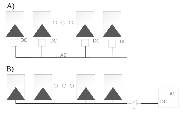
Typical PV micro-installations are equipped with a central inverter to which PV modules are connected in series (Fig. 1A). This solution means that all modules must operate with the same power, which translates into a decrease in the efficiency of the system. An alternative is systems with microinverters, which involve the introduction of direct DC/AC conversion on individual panels (Fig. 1B). Their use improves the possibilities of expanding the installation and minimizes losses associated with partial shading of the panels. Microinverters sometimes have a module enabling remote communication, which allows monitoring the operation of each module separately. This allows for a detailed examination of the operating conditions of the installation and their optimization. Unfortunately, the use of microinverters is associated with an increase in installation costs and a reduction in its operating time [9]. These elements are exposed to operation in extreme conditions (large temperature gradients up to 120 °C, precipitation, etc.), which reduces their service life and increases the risk of failure. It should also be taken into account that all operating activities are significantly difficult due to the location of the microinverter directly next to the PV panel. According to many PV system installers, in most cases access to the microinverters is difficult. In order to perform service activities, it is usually necessary to dismantle one or even several PV panels, which significantly complicates and prolongs the repair process.
It should be also mentioned that there are single-phase and three-phase inverters. The former are most often used in low-power installations, because according to the recommendations of the EN 50438 standard, the rated current of a single phase should not exceed 16 A [10], which in the case of a standard voltage of 230 V translates into a power of 3.68 kW. The latter is used in higher power installations, as they allow for limiting the current value and evenly introducing energy into each phase. This affects smaller voltage fluctuations in the network and allows for the use of smaller cross-sections of wires.
Major criteria for inverter selection
The criteria for selecting an inverter for an installation vary depending on its type. In the case of an installation using microinverters, it should be checked whether the open circuit voltage (Uoc) and short circuit current (Isc) of a single module do not exceed the maximum value supported by the device. Traditional PV micro-installations with a central inverter should be designed in such a way that the voltage generated by the individual strings falls within the range of the inverter input voltage. In addition, the permissible number of strings supported by a given inverter and its maximum input current should be taken into account. The International Protection Rating (IP) that determines the location of the inverter installation is also important – in the case of outdoor applications, IP65 or higher is required [11] Regardless of which of the above technical solutions will be used, it is worth considering that they have appropriate certificates proving their quality, which translates into long-term failure-free operation. In addition, such devices provide output parameters compatible with the power grid and meet legal requirements. For economic reasons, it is also worth paying attention to the efficiency of the inverter, because devices with higher efficiency provide better energy conversion and lower losses. Additionally, it is worth considering the use of inverters with built-in protection (e.g. against overvoltages) and the ability to monitor the condition of the PV installation. This significantly improves the operational safety of a given PV system [12].
Another aspect is the issue of selecting the appropriate ratio of the peak power of the PV installation (PPV) to the rated power of the inverter (Pinv). This problem concerns primarily systems with a central inverter. This issue is not regulated by law, but inverter manufacturers recommend that the value of Pinv/PPV < 1. The need to undersize the inverter power results from ensuring optimal conditions for its operation – it achieves the highest efficiency when working under rated load [13]. The power of the PV installation is usually determined in the so-called STC (Standard Test Conditions) or NOCT (Normal Operating Cell Temperature) conditions, but in reality the achieved values of this parameter are significantly lower [14]. The actual performance of the PV installation should be determined based on properly conducted as-builts measurements [15].
Optimal selection of PV inverter power
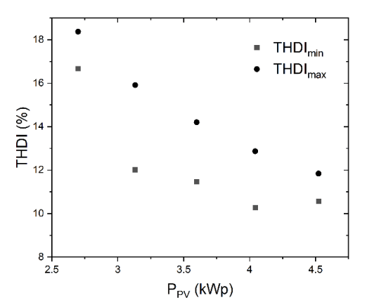
In order to illustrate the issue of selecting the inverter power for a PV installation, an experiment was conducted using a three-phase HPT-4000 inverter (Imax = 15.6 A; 180 V < UPV < 850 V; Pinv = 4 kW). The Keysight PV8921A PV installation simulator was used in the investigations, which has the following parameters: Uout = 1500 V; Imax = 30 A Pmax = 20 kW. The measurements were carried out employing MI2292 power quality analyzer. In Fig. 2 is presented the dependence of the inverter efficiency (η = PAC/PDC) in a function of a power generated by the PV installation. It can be observed, that the efficiency of the energy conversion process is highest when the inverter input is loaded with power close to its maximum power. Exceeding the Pinv results in the activation of the built-in protections, therefore the η value drops. The efficiency of the inverter also decreases when it is underloaded. In addition, the Total Current Distortion coefficient (THDI) increases, which reflects the quality of the generated electricity [16]. In Fig. 3 shown, that both the maximum and minimum values of the mentioned coefficient decrease with the load on the inverter, which indicates a decrease in the share of higher harmonics in the waveform of the generated current.
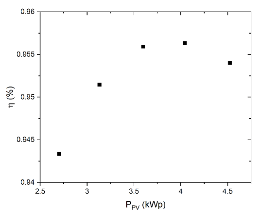
It should be emphasized here, that the actual power of the PV installation is lower than PPV, therefore it is recommended to use inverters with lower power. On the other hand, it is necessary to avoid a situation in which the inverter is unable to process the supplied electrical energy due to too low power. The optimal selection of the inverter is based on the fact that the energy losses resulting from the power limitation are lower than the increased energy gain resulting from the higher efficiency of the inverter.
PV Inverter Selection Case Study
In order to better illustrate the issue of selecting inverters for PV micro-installations, 14 real cases were analyzed. The research object was PV micro-installations located in northern Poland, which were checked in the context of the correctness of the inverter selection. The obtained results are gathered in Table 1.
Table 1. Summary of real cases of PV micro-installations in the context of the correctness of the inverter selection
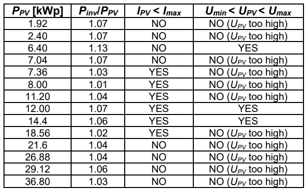
It can be observed that the main problem related to the selection of inverters is their oversizing in relation to the PV installation. In all the cases examined, the Pinv/PPV ratio was higher than 1, which, as shown above, is associated with reduced installation efficiency, i.e. lower power generated to the power system. In addition, the use of an oversized inverter increases the cost of the PV installation, thus extending the payback period. Another issue concerns exceeding the maximum permissible inverter current (Imax), which occurred in more than 57% of cases. This situation is potentially dangerous because it can lead to overheating of the inverter components and, consequently, to fire. It is also worth mentioning that in almost 79% of the examined cases the maximum permissible voltage (Umax) was exceeded, which may result in a shortened lifespan of the inverters.
Conclusions
The appropriate selection of an inverter for a PV microinstallation is crucial due to aspects related to efficiency and operational safety. The principles of selecting inverters vary depending on the type of PV installation (installation with a central inverter or microinverters) and its power (in the case of installations with higher power, three-phase inverters are usually used). Nevertheless, care should be taken not to exceed the maximum permissible values of input voltage and current for a given device. Moreover, the designer should ensure that the components used are characterized by high quality of workmanship and comply with applicable regulations, as evidenced by appropriate certificates. It is also worth choosing inverters with higher efficiency. Another issue is the selection of the optimal power of the inverter for a PV micro-installation. Undersizing the inverter in relation to the power of the PV installation results in a higher electrical energy yield due to its more efficient operation. Furthermore, in the long term, PPV decreases due to the aging processes of PV modules, which additionally reduces the efficiency of micro-installations with underloaded PV inverters. Analysis of real cases has shown that there are problems with the appropriate selection of inverters for PV micro-installations (especially with the appropriate selection of Pinv/PPV). In this matter, specialist software such as BlueSol [17] can be helpful, however, the final decision on the selection of specific components always remains with the designer.
Thanks to ERKON Tech Sp. z o.o. for providing the data necessary for the analyses described in this article.
REFERENCES
[1] F. Baumgartner, “5 – Photovoltaic (PV) balance of system components: Basics, performance,” in The Performance of Photovoltaic (PV) Systems, N. Pearsall, Ed., Woodhead Publishing, 2017, pp. 135–181. doi: https://doi.org/10.1016/B978-1-78242-336-2.00005-7.
[2] N. G. Dhere, “Reliability of PV modules and balance-of-system components,” in Conference Record of the Thirty-first IEEE Photovoltaic Specialists Conference, 2005., 2005, pp. 1570–1576. doi: 10.1109/PVSC.2005.1488445.
[3] S. Czapp, K. Seklecki, L. Litzbarski, and M. Olesz, “Zagrożenie porażeniem podczas gaszenia pożaru w budynkach z fotowoltaicznymi źródłami energii ,” Przegląd Elektrotechniczny, vol. 12, pp. 66–72, 2024.
[4] L. Litzbarski, M. Olesz, K. Seklecki, and M. Nowak, “Ryzyko strat odgromowych a systemy fotowoltaiczne,” Przegląd Elektrotechniczny, pp. 293–295, 2023.
[5] H. Boryń, “Ochrona odgromowa fotowoltaicznych źródeł energii elektrycznej,” Zeszyty Naukowe Wydziału Elektrotechniki i Automatyki Politechniki Gdańskiej, pp. 21–26, 2010.
[6] K. Seklecki, L. Litzbarski, K. Wójcik, Z. Cieślikowska, M. Włas, and J. Grochowski, “Instalacje fotowoltaiczne w budownictwie wielorodzinnym,” Przegląd Elektrotechniczny, pp. 79–81, 2024.
[7] M. C. Falvo and S. Capparella, “Safety issues in PV systems: Design choices for a secure fault detection and for preventing fire risk,” Case Studies in Fire Safety, vol. 3, pp. 1–16, 2015,
[8] M. Sarniak, “Fotowoltaika w układach zasilania budynków,” Elektro Info, vol. 9, pp. 64–68, 2015.
[9] Ö. Çelik, A. Teke, and A. Tan, “Overview of micro-inverters as a challenging technology in photovoltaic applications,” Renewable and Sustainable Energy Reviews, vol. 82, pp. 3191–3206, 2018, doi: https://doi.org/10.1016/j.rser.2017.10.024.
[10]K. Sereja and R. J\kedrychowski, “System zarz{\k{a}}dzania sieci{\k{a}} nn w świetle wymagań normy PN-EN 50438,” Poznan University of Technology Academic Journals. Electrical Engineering, 2018.
[11]PN EN 60529 : 2003 AC 2017Degrees of protection provided by enclosures (IP Code). 2003.
[12]K. Sarita, R. K. Saket, and B. Khan, “Reliability, availability, and condition monitoring of inverters of grid-connected solar photovoltaic systems,” IET Renewable Power Generation, vol. 17, no. 7, pp. 1635–1653, 2023, doi: https://doi.org/10.1049/rpg2.12700.
[13]M. Pilinski, “Optymalny dobór falownika do instalacji PV,” GLOBEnergia: Odnawialne Źródła Energii, no. 2, 2018.
[14]H.-F. Tsai and H.-L. Tsai, “Implementation and verification of integrated thermal and electrical models for commercial PV modules,” Solar Energy, vol. 86, no. 1, pp. 654–665, 2012, doi: https://doi.org/10.1016/j.solener.2011.11.014.
[15]L. Litzbarski, M. Olesz, and K. Seklecki, “Measurement practice of photovoltaic installations leading to the determination of the actual technical condition; [Praktyka wykonywania pomiarów instalacji fotowoltaicznych prowadząca do określenia rzeczywistego stanu technicznego],” Przeglad Elektrotechniczny, vol. 2024, no. 3, pp. 82 – 84, 2024, doi: 10.15199/48.2024.03.14.
[16]J. A. Pomilio, J. P. Bonaldo, H. K. Morales-Paredes, and P. Tenti, “About power factor and THDi in the smart micro-grid scenario,” in 2015 IEEE 13th Brazilian Power Electronics Conference and 1st Southern Power Electronics Conference (COBEP/SPEC), 2015, pp. 1–5. doi: 10.1109/COBEP.2015.7420183.
[17]K. Kut Paweł and Nowak, “Design of Photovoltaic Systems using Computer Software,” Journal of Ecological Engineering, vol. 20, no. 10, pp. 72–78, 2019,
Authors: mgr inż. Konrad Seklecki, E-mail: konrad.seklecki@pg.edu.pl; dr inż. Leszek Litzbarski, E-mail: leszek.litzbarski@pg.edu.pl; dr hab. inż. Marek Olesz, E-mail: marek.olesz@pg.edu.pl; Emanuel Gifuni, E-mail: s194407@student.pg.edu.pl; prof. dr hab inż. Grzegorz Redlarski, , E-mail: grzegorz.redlarski@pg.edu.pl; Gdansk University of Technology, Faculty of Electrical and Control Engineering, Gabriela Narutowicza 11/12, 80-233 Gdańsk; Jacek Grochowski, Poznan University of Technology, Faculty of Control, Robotics and Electrical Engineering Piotrowo 3a, 60-965 Poznań, E-mail: jacek.grochowski@student.put.poznan.pl
Source & Publisher Item Identifier: PRZEGLĄD ELEKTROTECHNICZNY, R. 101 NR 5/2025. DOI: 10.15199/48.2025.05.26

