Published by 1. Pawan Kumar PANDEY1, 2. Ramesh KUMAR2, 3. Manish SINGLA2,3, 4. Sergey KOKIN4, 5. Murodbek SAFARALIEV4, 6. Javod AHYOEV3, Gyan Ganga Institute of Technology and Sciences (1), Chitkara University Institute of Engineering and Technology (2), Applied Science Private University (3), Ural Federal University (4), Tajik Technical University Named After Academician M.S. Osimi (5)
ORCID: 1. 0000-0002-5157-2485; 2. 0000-0001-9822-8246; 3. 0000-0003-1028-2729; 4. 0000-0001-7493-172X; 5. 0000-0003-3433-9742; 6. 0000-0002-9869-288X;
Abstract. Presently, the energy sector is more important for everyone according to consumption, production, distribution, and monitoring. So this study mainly focuses on the improvement of the power factor through fully automated. This paper introduces a system, which is based on the Internet of Things (IoT). This system works fully automated with improvements in power factor and also monitors the consumption of energy, which will accurately calculate all the parametrical data to display such as power, current, power factor consumption etc. The parametrical data can be accessed and obtained from the wireless technology Through the IoT Blink platform with a Web server. The parametrical data measurement and monitoring through the Controller unit, which is calculated and transmitted to the bank of capacitors through the relays compensates for the lagging power factor in this system. In the end the show the result of the correction in power factor, can be more efficient monitored the power losses and consumption in energy.
Streszczenie. Obecnie sektor energetyczny jest ważniejszy dla wszystkich ze względu na zużycie, produkcję, dystrybucję i monitorowanie. Dlatego też niniejsze badanie koncentruje się głównie na poprawie współczynnika mocy poprzez pełną automatyzację. W artykule przedstawiono system oparty na Internecie Rzeczy (IoT). System ten działa w pełni automatycznie, poprawiając współczynnik mocy, a także monitoruje zużycie energii, co dokładnie oblicza wszystkie dane parametryczne do wyświetlenia, takie jak moc, prąd, zużycie współczynnika mocy itp. Dostęp do danych parametrycznych i ich uzyskanie można uzyskać za pośrednictwem bezprzewodowego technologia Poprzez platformę IoT Blink z serwerem WWW. Pomiar i monitorowanie danych parametrycznych za pośrednictwem jednostki sterującej, które są obliczane i przesyłane do zespołu kondensatorów za pośrednictwem przekaźników, kompensują opóźniony współczynnik mocy w tym systemie. Na koniec pokaż wynik korekty współczynnika mocy, dzięki czemu możliwe będzie bardziej efektywne monitorowanie strat mocy i zużycia energii. (Automatyczna korekcja współczynnika mocy za pomocą mikrokontrolera w sektorze energetycznym)
Keywords: energy, power factor, internet of things, controller, capacitor bank.
Słowa kluczowe: energia, współczynnik mocy, Internet rzeczy, kontroler, bateria kondensatorów.
Introduction
Nowadays, the energy sector is based on consumption, production, distribution, and monitoring, which relates to the direct or indirect power factor. The power factor gives an important analysis of the electric supply system, which is more important as per all views of the energy sector [1]. And also identifies all types of losses in the utilization of the supply power such as power factor and losses are inversely proportional if the power factor is low then losses continually increase and power factor is high then losses continually improve. So the modern industry fully focuses on this factor and improves power factor use of different types the techniques and uses that relate the reactive power. The power consumption may be defined through the power factor, which is close to unity, and maintaining the help of shunt capacitor banks for Power Factor Correction (PFC) is an exceptionally established methodology [2].
Recently research in the energy sector mainly focused on automatic switching methodology, which is more important in real-time applications. Such as using the MCU embedded-based system [3], IoT embedded provides all types of correction monitoring and also controls all types of switching and monitoring [4]. This type of concept is used in modern industry and gets much more control as per the power factor, to provide the overall improvement in efficiency in the electrical system. The low power factor creates lots of losses and those losses reduce the shorter life of the equipment in the energy sector [5]. Therefore always maintain the power factor value between 0 and 1. The near value of power factor 0.95 is good for any electric system. So the above improvement in power factor is much more important in the electric system as per the electric standard [2-9].
Literature Review
The energy sector today revolves around the consumption, production, distribution, and monitoring of energy, all of which relate to the power factor. A key focus in the energy industry is on automatic switching methods to control the power factor, as this is crucial for real-time applications and others. Past research on improving the power factor in the advancing energy sector has been limited, with only a few studies on power factor correction, as summarized below.
In a 2017 paper, Machado et al. proposed a novel single-phase power factor correction (PFC) method using a parallel configuration, claiming it to be more efficient than the traditional two-stage cascade approach [10]. Earlier, Oommen and Kohler (1988) explored the advantages of proper power factor compensation, examining various compensator types, their optimal sizing, and placement strategies [11]. They also provided a brief economic analysis to highlight the cost-effectiveness of implementing such compensation techniques.
Choudhury (2008) designed a cost-effective power factor improvement device for small signal loads by modeling the load, selecting suitable capacitors, and implementing switching circuits to choose appropriate capacitor combinations [12]. Shohel et al. (2013) proposed a dynamic method for power factor correction and voltage regulation in light rail systems. This approach uses thyristors controlled by automatic power controllers to switch main reactors based on real-time power factor calculations derived from continuous current and voltage monitoring. The system improves the power factor by connecting inductive loads (reactors) in parallel with a capacitive system [7].
Shahid et al. (2013) proposed a cost-effective power factor correction circuit using a PIC microcontroller. This design prioritizes minimal components while maintaining efficiency. It utilizes an algorithm to analyze power factor and activate specific capacitors, ultimately compensating for reactive power and improving the overall power factor [15]. Mather et al. (2011) focused on this specific application. Through simulation and analysis, they proposed a modified boost converter with active control and a PI controller to ensure stable operation. Additionally, they designed a capacitor and inductor combination to address voltage and current ripple, input current distortion, and output voltage regulation [16, 17].
Power Factor and Correction
Power factor (PF) in an AC electrical power system measures the efficiency of power transmission. It’s the ratio of real power (the power actively doing work) to apparent power (the total power flowing in the circuit) [14]. Due to energy stored in the load or distortions in the current waveform, real power can be less than apparent power, resulting in a less efficient system [18]. The power factor is low due to the significant phase difference between the voltage and current at the load (May be distorted waveform/disrupted waveform sample or harmonic distortion contents) and this result directly reflated the result of the inductive loads, which relates to the motor, transformer, etc. So, we can say that the power factor has a poor nature affected due to inductive load and improves through the correction methodology, to improve all the parametrical data like distorted waveform, and harmonic distortion filters to gain an appreciable improvement [2]. The consumption of power to maintain the power factor between 0.9 to 0.95 and also beneficial to the all-electric system in all views of the energy sector [19-26].
The reason for the low power factor is due to the used equipment operated by the chokes (vapor lamps), in the transformer and induction motor. The transformer as per the distribution case has used a much more active nature and in this case, the power factor must be low [5]. On the other hand condition of the load (With load and without load) is due to the use of inductive loads such as pumps, converges, shovels, etc. Many methods and techniques are used for the improvement in power factor in the energy sector, which is implemented according to load conditions such as through automatic, fixed, and mixed (Automotive with fixed), which is under the Central unit based correction. In the other ways like individual power factor correction and group power factor correction. Both methods are much more important as compared to the central power factor correction because they relats on cost and maintenance in the energy sector [6].
The above methodologies have some benefits for correction in power factor and continuously improving using many ways such as to encourage efficiency surcharge of power factor, decreasing in demand charges, carrying capabilities are increased in used circulatory, advancement in regulation in voltage, reduce in losses of power system. The capacitor effect directly reduces the losses as per the current and those losses are directly proportional to the current squared. So we say that the reduction in current is directly proportional to improvement in the power factor and the losses are inversely proportional to the square of the power factor [7]. Which is a relatively small one-third of 1 percent of the KVAr rating.
Design Methodology
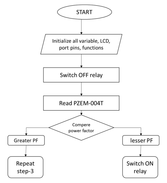
The proposed electric system is fully automated through the IoT-embedded technology. This system calculates the voltage and current from the sample obtained from the system after that to define the phase angle with the help of the input concerning the difference of the arrival waveforms. The assessment of difference with the help of an internal timer and phase angle, calculates the simple power factor.
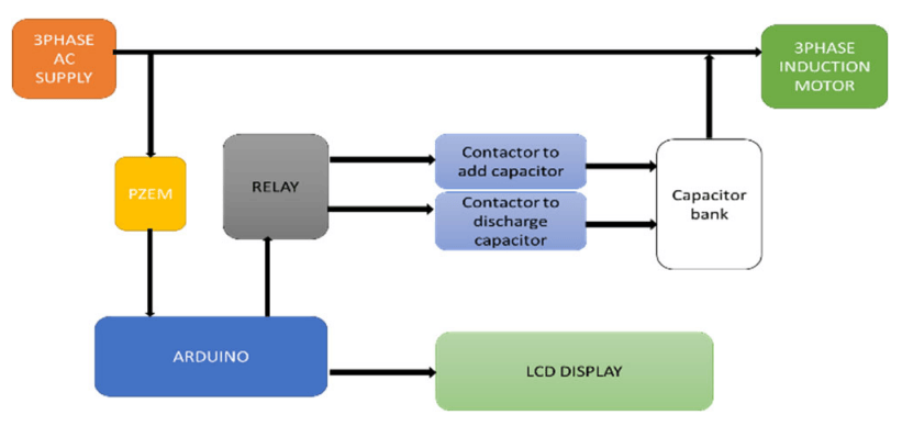
The system compared its power factor against a target level. This difference is used to automatically turn on or off the needed number of capacitors from the bank. The current power factor and phase lag are displayed for easy monitoring. As per the algorithm step wise, from the input, take the value of the current and voltage in the electric circuit. After that to calculate the phase lagging, power factor, and reactive power requirements. From the obtained parametrical data to create the differentiation between reactive power requirement and power factor. After Differentiate to define the Switching system (ON/OFF), which is connected to the capacitor bank depending on reactive power supplied by each step. In the Final step, compare the targeted value of the power factor with the simple power factor, afterward, correct the power factor and move on to the initial step.
Design & Implementation
This part outlines the in-depth design of each module of the suggested power factor correction device as well as the functioning of each component. Every module comprises numerous parts linked in the necessary manner to produce the intended result. The full schematic diagram is given at the conclusion based on which the construction was finished. Particular attention was paid during the assembly to prevent any short circuit of tracks during intersection of paths. The PZEM-004T Current Transformer is also the PZEM-004T 100 Ampere which utilizes the Current Transformer split core model. Since it uses a split core, it naturally has benefits in its simplicity of use as it can be directly set up on an already installed power network cable without having to remove the power cable. In the power supply utilizing 3 phase induction motor, 440-volt supply is provided to the load by an auto transformer and the microcontroller Arduino UNO needs 5v DC supply which is given by an adapter.
The PZEM-004T is an electronic module that functions to measure, like power, Current, Voltage, Frequency, Energy and Power Factors. With the fullness of these proficiencies, the PZEM-004T module is ideal for use in this experiment for measuring power on an electrical system. The MCU unit used the Arduino UNO, It is a microcontroller board founded on the ATmega328P. It possesses 14 digital input/output pins (of which 6 can be utilized as PWM outputs), 6 analog inputs, a 16 MHz ceramic resonator, a USB connection, a power jack, an ICSP header and a reset button. In an IoT Based embedded system, the microcontroller engages with the exterior world employing input and output devices that connect straight with a human being [16]. One of the most prevalent devices attached to the microcontroller is an LCD display.
Three control lines and four or eight I/O lines are required for the data bus connection to the microcontroller. A relay is a switch that operates electrically. Relays are used when several circuits need to be governed by a single signal or when it is necessary to regulate a circuit with a low-power signal (with complete electrical segregation between control and regulated circuits). Relay driver ULN2003 is utilised since the microcontroller’s output pin cannot supply enough current for the relay coil to activate the relay. An array of Darlington transistors with high voltage and high current is called ULN2003.
Large air conditioners and other strong three-phase equipment are controlled by a specialized switch called a three-phase contactor. Regular switches are unable to withstand the enormous power (480 volts or more) demanded by these devices, hence they are necessary. A shunt capacitor bank is an additional device that enhances the efficiency and flow of power. It functions similarly to a tiny battery that may be turned on or off based on the requirement for electricity. As a result, less energy is lost and the voltage level is kept constant. They are simple to put anyplace in the system and are reasonably priced. Lastly, a frequent electric motor type found in a variety of applications is the three-phase squirrel cage motor. The “cage” of wires within the motor, which resembles a squirrel cage, is where the term comes from.
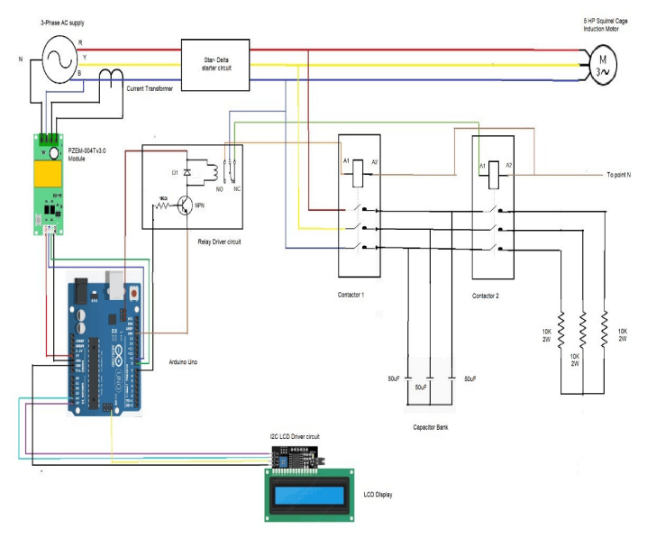
The load is three phase induction motor thus to improve the power factor APFC is developed. There is different type of components are used such as PZEM-004TV30, Arduino Uno, relay, 3 pole contactors, 50 micro farad capacitors, x/1 current transformer ,16*2 LCD display. 440 v supply is given to the motor and PZEM is directly connected to the phase to measure the current and voltage, PZEM calculated the angle between voltage and current waveform to determine power factor. A microcontroller is used to give the command by programming so that capacitor is being connected to the load when there is a condition of low power factor. Microcontroller is connected to the relay that operates the contactor to add the capacitor in the circuit it is also connected to the display which shows the different parameters such as voltage, current, angle power factor, frequency, active power, reactive power, apparent power.
Results & Discussions
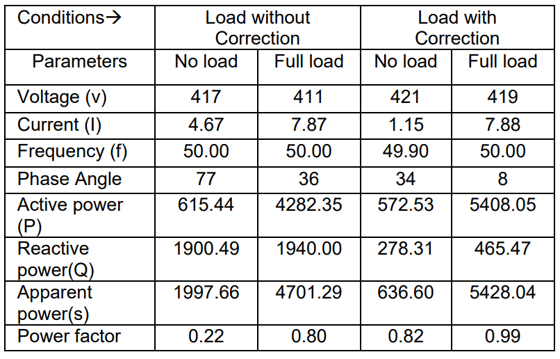
The validation of the proposed system is verified after it is used and the expected result is achieved. The correction in power factor using this system and verifying the desired correction with the working for suitability. Finally to achieve a suitable parametrical analysis for all monitoring desired outcomes for the electric system and load. From the Proposed system, the parametrical analysis is according to load conditions (With and without load) as shown in Table 1.
The parametrical analysis consists of different parameters measured values like current, voltage, power factor, phase angle, etc. by the load, power consumed, and power factor are essential to be measured for each case. That analysis is important of necessary to monitor for the consequent energy savings.
Table 1. Parametrical Analysis of the System
Conclusion
This study investigated the effectiveness of power factor correction equipment employing a microcontroller and capacitor banks. The equipment was designed for measurement and monitoring of a demonstrated electrical load, and the results demonstrated significant improvement in power factor. Under full load conditions, the device successfully enhanced the power factor from 0.80 to 0.99. Similarly, during no-load conditions, the power factor increased from 0.22 to 0.82. This design holds promise for real-world application with safety standards according to the energy sector. However, frequent load fluctuations in automatic power factor correction systems can lead to harmonic issues due to repeated capacitor bank switching. This research outcomes can be directed towards designing suitable filters and optimizing algorithms based on specific load change patterns, thereby minimizing preventable capacitor switching.
Acknowledgment: This research received no external funding.
REFERENCES
[1]. Yasin K., Yusuf M. M., and Mohammad M. K. (2017). Automated Power Factor Correction and Energy Monitoring System. Department of Electrical and Computer Engineering, North South University Bashundhara R/A, Dhaka1229, Bangladesh, 6pp
[2]. Yadav, A. R., Waghmode, S.S., Gawade, G. B., Zinjade, S. S. and Patil, P. T. (2016): A review on Microcontroller Based Automatic Power Factor Correction. International Journal of Advanced Research in Electrical, Electronics and Instrumentation Engineering, 5 (3): 1517-1520.
[3]. Kumar, R., Ratnesh, R. K., Singh, J., Chandra, R., Singh, G., & Vishnoi, V. Recent Prospects of Medical Imaging and Sensing Technologies Based on Electrical Impedance Data Acquisition System. In Journal of The Electrochemical Society, Vol. 170, Issue 11, p. 117507, 2023
[4]. Kumar, Ramesh, Ratneshwar Kumar Ratnesh, Jay Singh, Ashok Kumar and Ramesh Chandra, IoT-Driven Experimental Framework for Advancing Electrical Impedance Tomography, ECS Journal of Solid State Science and Technology, Volume 13, Number 2, 13 027002, 7 February 2024
[5]. Tiwari K., Sharma D., and Sharma V. (2014), Automatic Power Factor Correction Using Capacitor Bank, International Journal of Engineering Research and Applications, 4 (2): 393-395.
[6]. Taye, A. (2018). Design and Simulation of Automatic Power Factor Correction for Industry Application. International Journal of Engineering Technologies and Management Research, 5 (2): 10-21.
[7]. Shohel, M. R., Miah, M. N., and Rahman H. (2013). Automatic Power Factor Improvement by using Microcontroller. Global Journal of Researches in Engineering Electrical and Electronics Engineering, 13(6): 29-34.
[8]. M. Sharma et al., “Miniaturized Quad-Port Conformal Multi-Band (QPC-MB) MIMO Antenna for On-Body Wireless Systems in Microwave-Millimeter Bands,” in IEEE Access, vol.11, pp. 105982-105999, 2023, doi:10.1109/ACCESS.2023.3318313.
[9]. Gupta, Anupma, Vipan Kumar, Shonak Bansal, Mohammed H. Alsharif, Abu Jahid, and Ho-Shin Cho. “A Miniaturized Tri-Band Implantable Antenna for ISM/WMTS/Lower UWB/Wi-Fi Frequencies.” Sensors 23, no.15 (2023): 6989.
[10]. Machado, P.P. Jr., and Abud T. P. (2017). Power Factor Metering System Using Arduino. Fluminense Federal University, Electric and Telecommunications Engineering Master Program – PPGEET Niterói, Rio de Janeiro, Brazil. 6pp.
[11]. M. Oommen and J. L. Kohler, “Power factor and power factor control alternatives for mines,” Conference Record of the 1988 IEEE Industry Applications Society Annual Meeting, Pittsburgh, PA, USA, 1988, pp. 1209-1215 vol.2, doi: 10.1109/IAS.1988.25213.
[12]. Choudhury, S.M. “Design and Implementation of a low cost power factor improvement device”, IEEE Region 10 Conference, 2008.
[13]. Gupta, A., Yadav, S.K., Sharma, N. et al. Optimization of Bandwidth and Reflection Coefficient with HighGain Truncated Triangular-Shaped DRA Antenna Using NSGAII Algorithm. Iran J Sci Technol Trans Electr Eng 47, 1731–1742 (2023).
[14]. Nikita Hamilpurkar , Bhagyashree , P Sharadha , Shweta , Prashant, Minimizing Penalty in Industrial Power Consumption by Engaging APFC Unit, ICONIC RESEARCH AND ENGINEERING JOURNALS, IRE Journals, Volume 6 Issue 1, 1703702 531 , 2022
[15]. Shahid and A. Shabir, “Microchip based embedded system design for achievement of high power factor in electrical power systems,” 2013 IEEE PES Asia-Pacific Power and Energy Engineering Conference (APPEEC), Hong Kong, China, 2013, pp. 1-5, doi: 10.1109/APPEEC.2013.6837130.
[16]. Kumar, R., Kumar, S., & Sengupta, A. (2022). Optimization of Bio-Impedance Techniques-Based Monitoring System for Medical & Industrial Applications. IETE Journal of Research, 68(5), 3843-3854.
[17]. Mather, B.A.; Maksimovi ć, D. A simple digital power factor correction rectifier controller, IEEE Transactions on Power Electronics, pp 9-19, 2011.
[18]. Md. Abdur Rahman, Saleh Mohammad Tahsin, Dipta Das, Raihan Chowdhury, “Power factor Controlling and Monitoring wirelessly through computer”, 2020 IEEE Region 10 Symposium (TENSYMP), pp.547-551, 2020.
[19]. Dzhuraev, S. et al., Computation of the zero-wire current under an asymmetric nonlinear load in a distribution network, Energy Reports, 8(2022), 563-573
[20]. Senyuk M., Beryozkina S., Ahyoev J., Zicmane I., Safaraliev M. Solution of the emergency control of synchronous generator modes based on the local measurements to ensure the dynamic stability, IET Generation, Transmission and Distribution, (2023), 17(1), 52-56
[21]. Bumtsend, U. et al., The unbalanced modes analyze of traction loads network, In 2020 Ural Symposium on Biomedical Engineering, Radioelectronics and Information Technology (USBEREIT) IEEE, (2020), 0456-0459
[22]. Asanov M.S. et.al.,The use of Petri computing networks for optimization of the structure of distribution networks to minimize power losses. Energy Reports, 6 (2020), 1337-1343
[23]. Asanov M.S. et al., Algorithm for calculation and selection of micro hydropower plant taking into account hydrological parameters of small watercourses mountain rivers of Central Asia, Int. J. Hydrogen Energy, 46 (2021), № 75, 37109-37119.
[24]. Asanova S.M., et. al. Optimization of the structure of autonomous distributed hybrid power complexes and energy balance management in them, International Journal of Hydrogen Energy 46.70 (2021), 34542-34549.
[25]. Ghulomzoda A. et al., Recloser-Based Decentralized Control of the Grid with Distributed Generation in the Lahsh District of the Rasht Grid in Tajikistan, Central Asia, Energies, 13 (2020), p. 3673.
[26]. Ghulomzoda A. et al., A Novel Approach of Synchronization of Microgrid with a Power System of Limited Capacity. Sustainability, 13(2021), p. 13975.
Authors: PhD Pawan Kumar Pandey, Department Electrical Engineering, Gyan Ganga Institute of Technology and Sciences Jabalpur, Jabalpur, Madhya Pradesh 482003 India. E-mail: pkpnitj@gmail.com;
PhD Ramesh Kumar, Department of interdisciplinary courses in Engineering, Chitkara University Institute of Engineering and Technology, Chitkara University, Punjab, India 140401, rameshkumar.meena@chitkara.edu.in.;
PhD Manish Singla, Department of interdisciplinary courses in Engineering, Chitkara University Institute of Engineering and Technology, Chitkara University, Punjab, India 140401, Applied Science Research Center, Applied Science Private University, Amman 11931, Jordan. manish.singla@chitkara.edu.in.;
D.Sc Sergey Evgenevich Kokin, Department of Automated Electrical Systems, Ural Federal University, 19, Mira Street, Yekaterinburg, 620002, Russian Federation, e-mail: s.e.kokin@urfu.ru;
PhD Murodbek Kholnazarovich Safaraliev , Department of Automated Electrical Systems, Ural Federal University, 19, Mira Street, Yekaterinburg, 620002, Russian Federation, e-mail: murodbek_03@mail.ru;
PhD Ahyoev Javod Salamshoevich, Department of Electric stations, academicians Rajabov’s avenue 10, 734042, Dushanbe, Republic of Tajikistan, e-mail: javod@ttu.tj;
Conflict of Interest: The authors declare no conflict of interest
Source & Publisher Item Identifier: PRZEGLĄD ELEKTROTECHNICZNY, ISSN 0033-2097, R. 100 NR 10/2024. doi:10.15199/48.2024.10.12

