Published by 1. Bartłomiej GARDA, 2. Karol BEDNARZ, AGH University of Krakow
ORCID: 1. 0000-0001-6150-5617; 2. 0009-0007-6857-4851
Abstract. The objective outlined in the paper is to conduct reliable measurement tests on memristor behavior in three-phase systems. Memristors, acting as nonlinear elements, exhibit intriguing phenomena within such systems. Various configurations, including Delta and Wye connections with three and four wires, have been tested. The collected data has been analyzed and presented, with additional frequency analysis using FFT and assessment of total harmonic distortion factors. The acquired data has been modelled using the MMS memristor model and compared with the actual data.
Streszczenie. W artykule przedstawiono wyniki testów pomiarowych opisujących zachowania memrystorów w systemach trójfazowych. Memrystory, jako nieliniowe elementy, wykazują˛ intrygujące zjawiska w takich systemach. Przetestowano różne konfiguracje, w tym połączenia w trójkąt, w gwiazdę z trzema i czterema przewodami. Zebrane dane zostały przeanalizowane i przedstawione. Dokonano analizy częstotliwościowej FFT oraz wyznaczono współczynniki całkowitego zniekształcenia harmonicznego THD. Następnie uzyskane wyniki pomiarowe zostały zamodelowane z wykorzystaniem modelu memrystora MMS i porównane z danymi rzeczywistymi. (Pomiary memrystorów w układach trójfazowych)
Keywords: memristor, measurements, memristive element, three-phase systems, nonlinear systems.
Słowa kluczowe: memrystor, pomiary, element memrystorowy, układy trójfazowe, układy nieliniowe.
Introduction
The successful discovery of the feasible memristor device in 2008, reported by HP Laboratories [1], marked a significant turning point, sparking considerable interest among scientific researchers. Faced with the limitations of computer memories, the primary focus shifted towards utilizing memristors as memory cells. Memristors, serving as non-volatile memory with the potential for multistability, emerged as promising candidates. Numerous research papers have explored this avenue, suggesting that the integration with CMOS technology may soon supplant current solutions. So, the applications of magnetic devices focus on microelectronics, which is not the only correct direction.
Beyond memory applications, research has unveiled various other potential implementations for memristors, such as electrostatic discharge protection [2], regulation elements in signal amplifiers [3], oscillators [4] or logic circuits [5]. In recent years, the concept of the so-called ’power memristor’ has grown. The idea is to use memristive elements in lightning protection systems, i.e. instead of traditional varistors. In [6] author proposes a combined over-voltage protecting device consisting of a memristor connected in series with a spark gap. The memristor is applied to dissipate the lightning surge energy and to break the short-circuit current. This simple example shows that analyzing the usage of memristive device in three-phase systems is noteworthy and can provide a basis for further research. In [7] authors carried out the computer simulations of symmetric three-phase systems with memristive loads. Continuing the work in this paper the aim of the research is to provide trustworthy laboratory experiment results of the three-phase systems with memristors. Memristors, acting as nonlinear elements, exhibit intriguing phenomena within such systems. Various configurations, including Delta and Wye connections with three and four wires, have been tested. The collected data has been analyzed and presented, with additional frequency analysis using FFT and assessment of total harmonic distortion factors. The high non-linearity of the memristor results in deformation of most of the signals in the system. Since the voltage of the neutral point is highly non-sinusoidal it affects other signals like phase voltage, phase currents, and delta voltages. A Fast Fourier Transform (FFT) is applied to the chosen signals in order to provide a frequency spectrum. On this basis a Total Harmonic Distortion (THD) parameter was calculated. All measurements were modeled using the MMS memristor model and further compared using the Simulink simulations.
Measurement
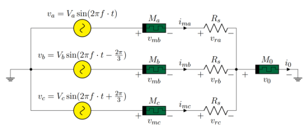
The authors used the three-channel generator NI-9263 and all data have been acquired by the compact 12-bit NI9201 device. The synchronization and acquisition process was performed using the LabVIEW environment. The tested device was a resistive device with chalcogenide ion conducting commonly known as SDC memristors, described in [8, 9]. Memristor SDCs can be doped with various metals, and in this work tungsten-doped memristors were used. To reduce the current, all memristors have been connected in series with the linear resistor Rs =5.1kΩ. All tests have been performed automatically for different frequencies and amplitudes of a three-phase symmetrical generator. The memristors have been connected in Delta and Wye, with and without the neutral wire. The example of a Wye conception with the neutral is shown in Figure 1. During the measurement five combinations of connections of the three-phase receiver have been applied, i.e. Delta (D), Wye (Y), Wye with neutral (YN), Wye with memristor in negative polarity in the neutral (YN−mN), and Wye with memristor in positive polarity in neutral (YN−mP). Hardware tests have been performed for all described connection combinations. The three-phase symmetrical generator was the three sinusoidal sources connected to the Wye of the same amplitude: {1.5,2,2.5,3} V for the Wye variation systems. In case of a Delta connection system, the above amplitudes were divided by 3 to obtain the same phase voltages on the load. The applied frequency belonged to the set {1,2,5,20,50,100} Hz. During the experimental procedure, a certain degree of measurement error was discerned. To mitigate errors attributed to high-frequency components present in the acquired data, the SavitzkyGolay filter [10] was used. The total acquired and filtered signals for 100 periods have been averaged down to one period.
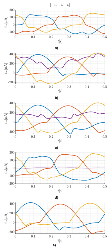
The example of the acquired and processed current signals for each connection combination can be observed in Figure~2. As expected, for all connections the all three phase currents are similar and shifted by ±120deg. Although the system seems to be symmetric, in the case when the fourth wire is attached, the neutral current is present. The effect is more noticeable for the YN connection. The presence of the memristor in the neutral wire decreases the neutral current value especially for the YN−mN connection. The memristor on the neutral wire works as some kind of diode and the current shape is similar to the three wire connection (Y). e)
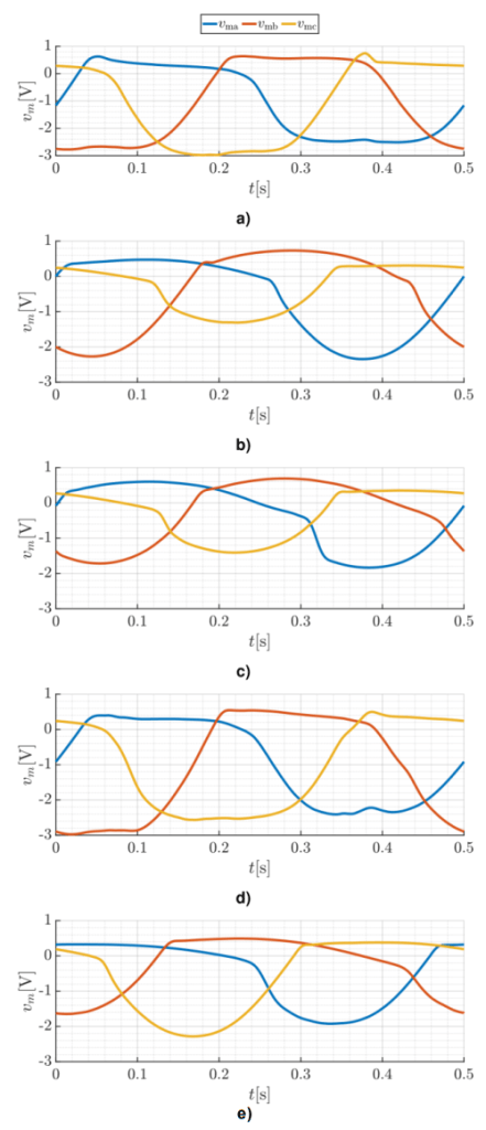
Anyhow it has to be point out that due to memristor’s high nonlinearity the respond signals are highly deformed from the sinusoidal. In the Figure 3 the corresponding voltages over memristors for all combinations of the connection are depicted. The voltage shape are also deformed but looks more similar and as expected shifted. The problem noticed here is the voltage peek values are different. For example, for D connection the problem can be neglected, but in case of YN the voltage vmc is much lower than vmb, especially for negative voltage.
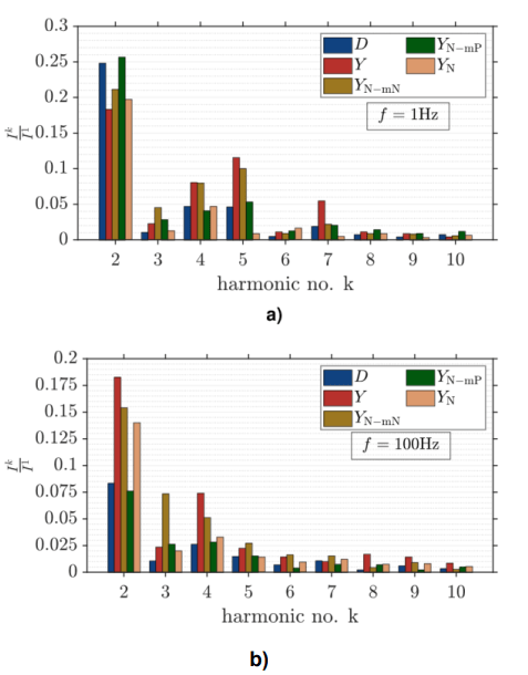
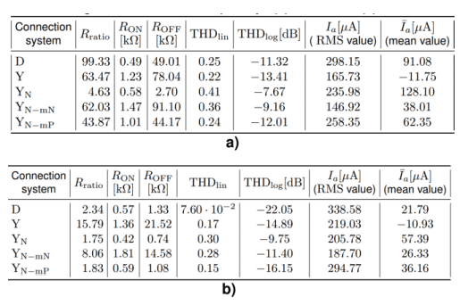
The order of the mentioned current signal deformation can be analyzed using the fundamental THD (Total Harmonic Distortion) parameter [11]. To calculate the THD parameter first the Fast Fourier Transform (FFT) needs to be carried out. In Figure 4 the amplitudes of the individual harmonics compared to the first harmonic are depicted. It can be observed that the amplitudes of the higher harmonic contribution become significantly smaller for the frequency of 100Hz compared to 1Hz. The actual values of the THD parameters can also be read in table 1.
Simulations
The acquired measurement data has been processed, and the parameters of the MMS memristor model [12] have been fitted using the nonlinear optimization method Sequential Quadratic Programming (SQP) [13]. A comprehensive explanation of fitting the memristor time series data to the specified model is provided in [14].
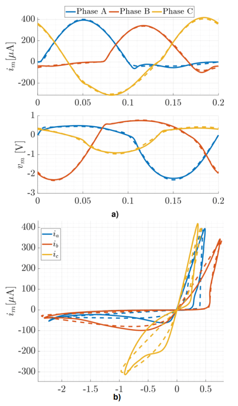
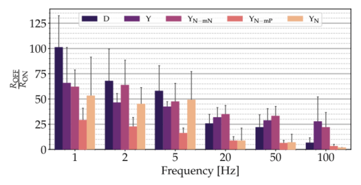
Using the model with the optimal parameters, Simulink simulations were conducted. The comparison between the measurements and the simulations for the Wye with neutral connection is illustrated in Figure 6. The high degree of agreement between the signals obtained from the measurements and the Simulink simulations validates the selection of the appropriate memristor model. Figure 6 depicts the characteristic memristor hysteresis loop, pinched at the origin in the v−i domain. Among the parameters of the MMS memristor model, RON and ROFF define the resistance range within which the memristor operates. The values of these resistances are presented in Table 1. The resistance ratio, defined as Rratio = ROFF/RON, is observed to be significantly higher at lower frequencies. This trend is further illustrated in Figure 5, where the resistance ratio decreases with increasing frequency for all connection combinations. This observation aligns with one of the memristor’s fingerprints defined by Chua, which states that “the hysteresis lobe area should decrease monotonically as the excitation frequency increases” [15], indicating that the resistance range between RON and ROFF is narrowing. This phenomenon also explains the increase in the RMS current value with frequency, as then the mean resistance decreases. The memristor element is not portwise symmetric, which results in a DC component in the current response. The values of the DC component are provided in
Table 1. It should be noted that the presence of a DC component also tends to decrease as the frequency increases. Table 1. Comparison of various connection types in terms of resistance ratio (Rratio), on-state resistance (RON), off-state resistance (ROFF), total harmonic distortion in linear scale (THDlin), total harmonic distortion in logarithmic scale (THDlog), RMS and mean value of phase a current. With power supply parameters: amplitude voltage Vs =3V, and frequency a) fs =1Hz, b) fs =100Hz.
Summary
As anticipated, the highly nonlinear memristor element exerts a significant impact in three-phase systems, specifically affecting the DC components across all phase signals. When connected in a Wye configuration with the memristor in positive polarity on the neutral wire, the memristor exhibits an intriguing low-frequency current signal, effectively acting as a rectifier. In particular, the total harmonic distortion (THD) factor decreases as the excitation signal frequency increases. This effect is less pronounced in Wye connections with a neutral wire. Depending on the connection type, the memristors behave differently, which can be observed with the RON and ROFF values. In addition, the effect of narrowing the interval between RON and ROFF is observed during frequency increase. Employing a Simulink simulation with the MMS memristor model yields highly reliable results, closely mirroring laboratory experiments.
Acknowledgments The research presented in the article was financed by the Polish Ministry of Science and Higher Education as part of a subsidy for AGH University of Krakow.
REFERENCES
[1] Dmitri B. Strukov et al. “The missing memristor found”. In: Nature 453.7191 (2008), pp. 80–83.
[2] G. Elmer et al. “Design thinking for innovation in 3D VR Over-Voltage Protection with Memristor”. In: 2020 11th IEEE International Conference on Cognitive Infocommunications (CogInfoCom). Mariehamn, Finland, 2020, pp. 417–424.
[3] Q. Li et al. “Study of the Noninverting Amplifier Based on Memristor with Linear Dopant Drift”. In: 2012 Second International Conference on Intelligent System Design and Engineering Application (ISdea). Sanya, China, 2012, pp.1136–1139.
[4] S. Weiheng, Chunfu Li, and Juebang Yu. “A memristor based chaotic oscillator”. In: 2009 International Conference on Communications, Circuits and Systems (ICCCAS). Milpitas, CA, USA, 2009, pp. 955–957.
[5] Yamtim S. and Tooprakai S. “Multi-input Memristor Rationed Logic Full Adder Circuit for Efficient Processing Time”. In: Przegla˛d Elektrotechniczny 98.6 (2022), pp. 88–94. ISSN: 0033-2097.
[6] Ildikó Horváth. “Simulation of a memristor-spark-gap model for lightning protection purposes”. In: Tehnicki Vjesnik 21 (Oct. 2014), pp. 1047–1050.
[7] Garda B. and Zegarmistrz P. “Memristive Devices In Three-Phase Systems”. In: Przegla˛d Elektrotechniczny 96.1 (Jan. 2020), pp. 11–14. ISSN: 0033-2097.
[8] Bartłomiej Garda and Karol Bednarz. “Comprehensive Study of SDC Memristors for Resistive RAM Applications”. In: Energies 17.2 (Jan. 2024), p. 467. ISSN: 1996-1073.
[9] Valerii Ostrovskii et al. “Structural and Parametric Identification of Knowm Memristors”. In: Nanomaterials 12.1 (2022). ISSN: 2079-4991.
[10] A. Savitzky and M.J.E. Golay. “Smoothing and Differentiation of Data by Simplified Least Squares Procedures”. In: Analytical Chemistry 36.8 (1964), pp.1627– 1639.
[11] D. Shmilovitz. “On the definition of total harmonic distortion and its effect on measurement interpretation”. In: IEEE Transactions on Power Delivery 20.1 (2005), pp. 526–528.
[12] T. W. Molter and M. A. Nugent. “The Generalized Metastable Switch Memristor Model”. In: CNNA 2016; 15th International Workshop on Cellular Nanoscale Networks and their Applications. 2016, pp. 1–2.
[13] Philip Gill and Elizabeth Wong. “Sequential Quadratic Programming Methods”. In: vol. 154. Nov. 2012, pp. 147–224. ISBN: 978-1-4614-1926-6.
[14] Bartłomiej Garda. “Modeling of Memristors under Periodic Signals of Different Parameters”. In: Energies 14.21 (2021). ISSN: 1996-1073.
[15] Shyam Prasad Adhikari et al. “Three Fingerprints of Memristor”. In: IEEE Transactions on Circuits and Systems I: Regular Papers 60.11 (2013), pp. 3008–3021.
Authors: Ph.D. Bartłomiej Garda, M. Sc Karol Bednarz, Department of Electrical and Power Engineering, Faculty of Electrical Engineering, Automatics, Computer Science and Biomedical Engineering, AGH University of Kraków, al. Mickiewicza 30 30–059 Kraków, Poland, email: bgarda@agh.edu.pl, kbednarz@agh.edu.pl
Source & Publisher Item Identifier: PRZEGLĄD ELEKTROTECHNICZNY, ISSN 0033-2097, R. 101 NR 2/2025. doi:10.15199/48.2025.02.13

