What is Harmonic Study and Analysis and Why it is Done?

Published by Carelabs (Carelabz)


Image: Carelabz

The current significant growth in electronic devices focusing providing our installations has given rise to a significant change in the last few years on the type of loads connected to the electrical distribution system. Not so long ago the only concern there was when using electricity at home, in establishments and productive centres was simply the voltage, without giving a thought to anything other than whether the equipment and devices were working or not.

These devices, present equipped electronics which in some way or another provide increased performance in the tasks and productive processes we carry out.

Everyone uses computers for their personal use, for the process, control of any production system with variable speed drives, air conditioning units, lifts which adjust slowly on approaching the destination floor etc. These devices equipped with promoters, modulators and distort the current wave form for them to work properly.

Technical costs are those which bring about a loss of performance on our installation.

  • Loss of capacity on energy distribution line
  • Transformer overload
  • Conductor overload
  • Voltage drop
  • Derating of transformers
  • Losses on lines and machines due to the Joule’s effect
  • Magnetic losses on electrical machines

Normally, all technical cost turn into economic costs. Here is where importance of control in our installation.

Economic costs are those which we can economically quantify, although in some cases it is difficult. These costs can  divide into hidden cost and visible costs.

  • Increased electricity consumption
  • Electricity consumption peaks
  • Surcharge or payment on reactive energy
  • Distribution losses
  • Power and energy loss (due to the Joule effect and magnets)
  • Enlargement of the installations
  • Stoppage of productive process

All these phenomena can find to a lesser or greater extent depending on the installation itself and the loads connected.

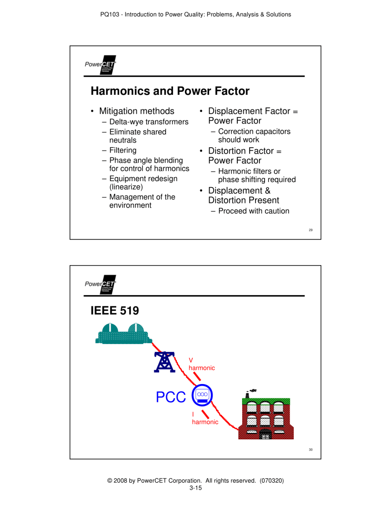
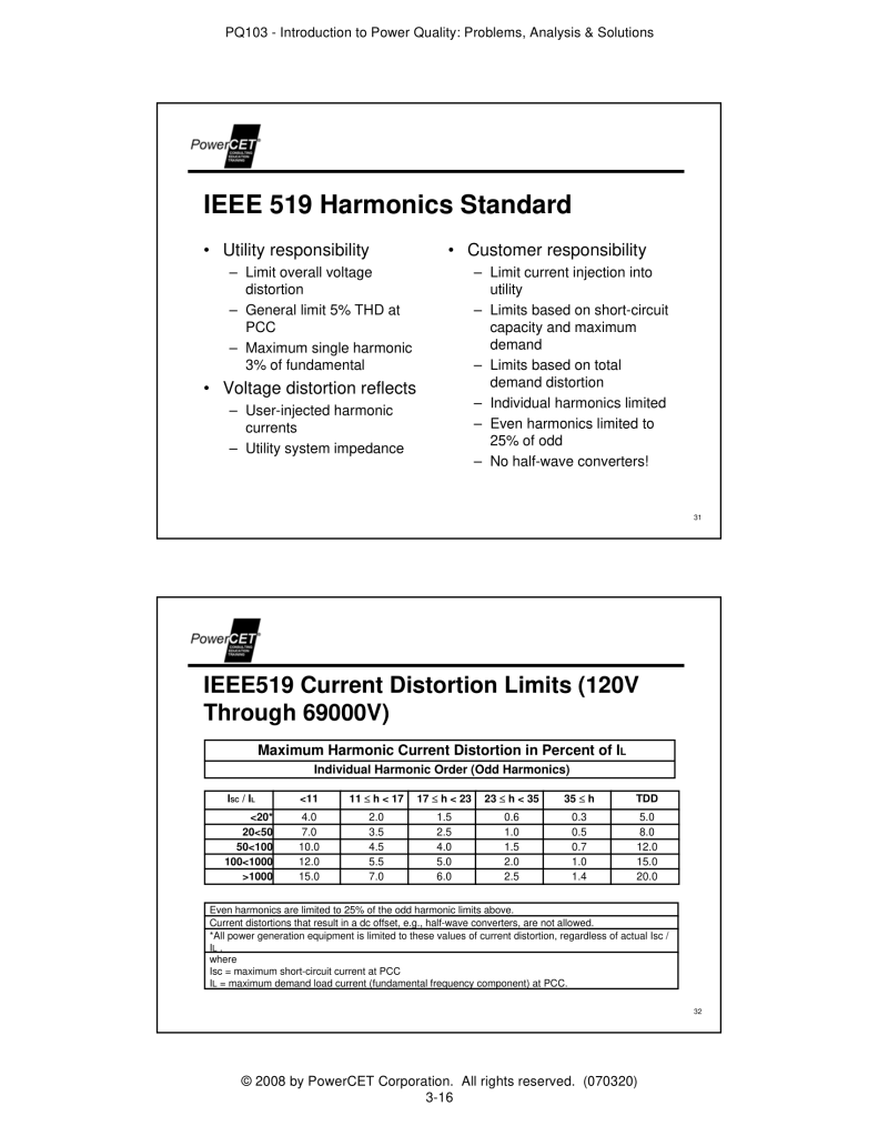
The main effects of the voltage and current harmonics in a power system can cited as:

  • The chance for elaboration of some harmonics as a result of serial and parallel resonance.
  • Performance reduction in generation, transport and energy usage systems.
  • The aging of the grid insulation peripherals and as issue, energy reduction.
  • Malfunctioning of the system or some of its elements.

However to understand these effects better we must know the nature of harmonics. Harmonics produced by not-linear loads that absorb non-sinusoidal current. The most common loads, both in industrial surroundings and domestic ones, are the following ones:

  • Frequency / Variable speed drives
  • Discharge lamps (high pressure sodium vapour lamp, mercury vapour lamp, low consumption, fluorescent)
  • Rectifiers
  • AC/DC Converters
  • Arc welding
  • Induction ovens
  • UPS
  • Computers and laptops

Harmonics are contortion of the normal electrical waveform, generally transmitted by nonlinear loads. Switch-Mode Power supplies variable speed motors drives, photocopiers, personal computers, laser printers, fax machines, battery chargers and UPSs are examples of nonlinear loads.

Single phase nonlinear loads existing in modern office buildings, while three-phase nonlinear loads are common in organisations and industrial plants. A great section of the non-linear electrical load on most electrical distribution systems comes from Switch-Mode Power Supplies equipment. For example, all computer systems use Switch-Mode Power Supplies that convert utility Air Conditioner voltage to regulated low-voltage DC for internal electronics.

These non-linear power supplies consume electricity in high-amplitude short pulses that create significant distortion in the electrical and voltage wave shape harmonic distortion, measured as Total Harmonic Distortion. The exaggeration travels back into the power source and affect other equipment connected to the same source. Most power systems can take certain level of harmonic currents but will experience problems when harmonics become a significant element of the overall load. As great frequency harmonic electricity flow through power system, would cause communication errors, overheating and hardware damage such as:

  • Overheating of electrical distribution equipment, cables, transformers, standby generators etc.
  • High voltages and circulating currents caused by harmonic resonance
  • Equipment defect due to excessive voltage exaggeration
  • High internal energy losses in connected equipment, causing component failure and shortened life span
  • False tripping of branch circuit breakers
  • Metering errors
  • Fires in wiring and distribution systems
  • Generator failures
  • Crest elements and related problems
  • Lower system element, resulting in fines on monthly utility bills

A standard transformer is not designed for high harmonic currents produced by non-linear loads. It will overheat and fail early when connected to these loads. When harmonics introduced into electrical systems at levels that showed adverse effects (about 1980), the industry responded by developing the K-rated transformer. K-rated transformers not meant for consonants, but they would handle heat produced by consonant electricity and efficiently used under their K-element value.

K-element ratings range between 1 and 50. A standard transformer designed for linear loads have K-element of 1. The higher the K-element, the more heat from harmonic currents the transformer is able to handle. Making the right choice of K-element is very important, because it affects cost and safety. The table shows proper K-element ratings to use for different percentages of non-linear current in the electrical system.

The K-rated transformer commonly used in electrical industries, have more growth in transformer design that offer better performance in decreasing  voltage exaggeration and power losses due to electric consonants. Eaton’s energy-efficient Harmonic Mitigating Transformer designed to handle the non-linear loads of today’s electrical infrastructures. This transformer uses electromagnetic reduction to deal exactly with the triplen (3rd, 9th, 15th etc.) consonants.

Secondary windings of the transformer arranged to cancel zero sequence fluxes and ignore primary winding circulating currents. This transformer addresses the 5th and 7th consonant by using phase shifting. Using electromagnetic strategies, Eaton Harmonic Mitigating Transformer allows promote in same aspect as their operator designed them, while decreasing impact of consonants to energy losses and exaggeration. Eaton Harmonic Mitigating Transformer exceeds NEMA TP-1 efficiency standards, even when analysed with 100% nonlinear loads.

Wherever a K-rated transformer specified, an equal Harmonic Mitigating Transformer is a direct substitute. Power ware PDUs supplied with Harmonic Mitigating Transformer are efficient and effective at reducing the consonants produced by computer equipment and other nonlinear electronic loads.

Advantages of using Power ware PDUs with Harmonic Mitigating Transformer

  • Prevents voltage flat-topping caused by non-linear loads
  • Reduces upstream harmonic currents
  • Eliminates transformer overheating and high operating temperatures
  • Eliminates primary winding circulating current
  • Saves energy by reducing harmonic losses
  • Maintains high energy efficiency even under severe non-loading conditions
  • Treats power quality harmonic issues that K-rated transformers do not address
  • Suitable for high K-element loads without increasing in-rush current
  • Improves power factor

Source: https://carelabz.com/what-how-harmonic-study-analysis-done/

What is Earth Grounding?

Published by Carelabs (Carelabz)


Image: Carelabz

IEEE defines earth as a conducting connection, whether intentional or accidental, by which an electric circuit or equipment is connected to the Earth, or to some conducting body of relatively large extent that serves in place of the earth. The connection(s) to Earth are done by an assortment of metallic means intended to be employed as a designated grounding electrode. A designated grounding electrode is the device that is intended to establish the direct electrical connection to the earth rod.  The designated grounding electrode might be a water pipe, steel columns of a building or structure, concrete encased steel reinforcement rods, buried copper bus, copper tubing, galvanized steel rods, or semi conductive neoprene rubber blankets.  Gas pipes and aluminum rods cannot be employed as grounding electrode The grounding electrode conductor is the designed conductor that is employed to connect A common designated grounding electrode is often a copper clad or copper flashed steel the grounding electrode(s) to other equipment grounding conductors, grounded conductor, and structure.  

Purpose of Earth Grounding 
  • Limit potential difference of neutral for system stability. 
  • Allow for operation of relays and system protections devices. 
  • Personnel safety. 

Practical Ground Resistance rods have much less than 160 Ω. Typical rod resistances will be less than 25 Ω in most soils because of the existence of proximate utility ground references. 

Low ground resistance (< 10 Ω ) can be achieved with: 

  • Multiple Rods bonded together 
  • Counterpoise system 
  • Coupled rods 

Grounding is thought by many to be synonymous with electrical safety. “If equipment is grounded then it is electrically safe” gives a false sense of security. The process that many consider to be “grounding” can and may minimize the severity of electrical faults when performed with an understanding of what happens during an electrical fault. “Grounding” is very specific; it means a connection to the earth (ground). With respect to systems, such as transformers, generators, or batteries, “grounding” generally means providing a connection from one conductor of the system to an electrode that is buried in the earth. However, not all systems are grounded nor is the electrode always in the earth. When referring to equipment, the term “grounding” can have various meanings. It may mean bonding or it may mean a direct connection to the earth. The term “bonding” sometimes may mean “grounding,” and sometimes, it may mean a short or a long connection. 

Earth Bonding 

“Bonding” is a method by which all electrically conductive materials and metallic surfaces of equipment and structures, not normally intended to be energized, are effectively interconnected together via a low impedance conductive means and path in order to avoid any appreciable potential difference between any separate points.   

The bonded interconnections of any specific electrically conductive materials, metallic surfaces of enclosures, electrical equipment, pipes, tubes, or structures via a low impedance path are completely independent and unrelated to any intended contact or connection to the Earth.   

The common mean to effectively bond different metallic surfaces of enclosures, electrical equipment, pipes, tubes or structures together is with a copper conductor, rated lugs, and the appropriate bolts, fasteners, or screws.  Other effectively bonding means between different metallic parts and pieces might employ brackets, clamps, exothermic bonds, or welds to make an effectively connections. 

In addition to preventing potential differences that may result in hazards, effectively bonded equipment can also be employed to adequately and safely conduct phase-to-ground fault current, induced currents, surge currents, lightning currents, or transient currents during such abnormal conditions.

The principle purposes for an “effectively bonded grounding system via a low impedance path to earth” are intended to provide for the following. 

  • Provide for an applicable reference to earth to stabilize the system voltage of a power distribution system during normal operations. 
  • Create a very low impedance path for ground fault current to flow in a relatively controlled path. 
  • Create a very low impedance path for ground fault current to flow in order for overcurrent protective devices and any ground fault protection systems to operate effectively as designed and intended. 
  • Limit differences of potential, potential rise, or step gradients between equipment and personnel, personnel and earth, equipment and earth, or equipment to equipment. 
  • Limit voltage rise or potential differences imposed on a power distribution system from lightning, a surge event, any phase-to-ground fault conditions, or the inadvertent commingling of or the unintentional contact with different voltage system. 

Source: https://carelabz.com/what-earth-grounding/

FLEX-CORE® Glossary of Terms

Published by FLEX-CORE®, Div. Morlan & Associates, Inc.


Current Transformers

Usually rated on a basis of 5 amperes secondary current and used to reduce primary current to usable levels for transformer-rated meters or transducers and to insulate and isolate them from high voltage circuits.

Current Transformer Ratio

Ratio of primary to secondary current. For a current transformer rated 200:5, the ratio is 200:5 or 40:1.

Current Transformer Burdens

Normally expressed in ohms impedance such as B-0.1, B-0.2, B-0.5, B-0.9, or B-1.8. Corresponding volt-ampere values are 2.5, 5.0, 12.5, 22.5, and 45.

Voltage Transformers

Are used whenever the line voltage exceeds 480 volts or whatever lower voltage may be established by the user as a safe voltage limit. They are usually rated on a basis of 120 volts secondary voltage and used to reduce primary voltage to usable levels for transformer-rated meters, transducers and other loads.

Voltage Transformer Ratio

Ratio of primary to secondary voltage. For a voltage transformer rated 4200:120, the ratio is 4200:120 or 35:1.

Voltage Transformer Burdens

Normally expressed as volt-amperes at a designated power factor. May be W, X, M, Y, or Z. W is 12.5 V.A. @ 0.10 pf; X is 25 V.A. @ 0.70 pf; M is 35 V.A.@ 0.20 pf; Y is 75 V.A. @ 0.85 pf and Z is 200 V.A. @ 0.85 pf. The complete expression for a current transformer accuracy classification might be 0.3 at B-0.1, B-0.2 and B-0.5, while the potential transformer might be 0.3 at W, X, M and Y.

Transformer Ratio – (TR)

Total ratio of current and voltage transformers. For a 200:5 C.T. and 480:120 P.T., TR = 40 X 4 = 160.

Weatherability

Transformers are rated as indoor or outdoor, depending on construction (including hardware).

Accuracy Classification

Accuracy of an instrument transformer at specified burdens. The number used to indicate accuracy is the maximum allowable error of the transformer for specified burdens. For example, 0.3 accuracy class means the maximum error will not exceed 0.3% at stated burdens.

Rated Burden

The load which may be imposed on the transformer secondaries by associated meter coils, leads and other connected devices without causing an error greater than the stated accuracy classification.

Relaying Accuracy of Current Transformers

A relaying accuracy class is designated by two symbols which effectively describe the capability of the transformer as follows:

1. C means the transformer ratio can be calculated, i.e. a window type current transformer with uniformly distributed windings. The C rating refers to a low reactance design.

2. The secondary terminal voltage rating is the voltage which the transformer will deliver to a standard burden at 20 times normal secondary current without exceeding 10% ratio error. Furthermore, the ratio error must be limited to 10% at any current from 1 to 20 times rated current at any lesser burden. For example, relay accuracy class C100 means that the ratio can be calculated and that the ratio error will not exceed 10% at any current from 1 to 20 times nominal secondary current if the burden does not exceed 1.0 ohms (1 ohm X 5 amp X 20 times normal current = 100 volts.)

Continuous Thermal Rating Factor – (TRF)

Normally designated for current transformers and is the factor by which the rated primary current is multiplied to obtain the maximum allowable primary current without exceeding temperature rise standards and accuracy requirements. Example – if a 400:5 C.T. has a RTF of 2.0, the C.T. will continuously accept 400 X 2 or 800 primary amperes with the 5 X 2 or 10 amperes from the secondary. The thermal burden rating of a voltage transformer shall be specified in terms of the maximum burden in volt-amperes that the transformer can carry at rated secondary voltage without exceeding a given temperature rise.

Rated Insulation Class

Denotes the nominal (line-to-line) voltage of the circuit on which it should be used. FLEX-CORE® has transformers rated for 600 volts though 15kV.

Polarity

The relative polarity of the primary and secondary windings of a current transformer are indicated by polarity marks associated with one end of each winding. When current enters at the polarity end of the primary winding, a current in phase with it leaves the polarity end of the secondary winding. Representation of primary marks on wiring diagrams are shown as black squares, black circles, or H1. Secondary marks are shown as black squares, black circles or X1.

Hazardous Open-Circuiting

Operation of C.T.’s with the secondary winding open can result in a high voltage across the secondary terminals which may be dangerous to personnel or equipment. Therefore, the secondary terminals should always be short-circuited before a meter or other load is removed from service. It is recommended that shorting blocks or knife switch shorting assemblies be used with current transformers.


Source: https://www.flex-core.com/engineering-resources/glossary-of-terms/

What & Why of PFC and PSC Test?

Published by Carelabs (Carelabz)


Image: Carelabz

Prospective Short Circuit (PSC) and Prospective Fault Current (PFC) are both designed to calculate the maximum current that will flow within a fault loop path during the event of an electrical fault as required by regulations. 

The Prospective Short Circuit Current is the maximum current that could flow between Line and Neutral conductors on a single phase supply or between Line conductors on a three phase supply. A PSC test calculates the current that will flow in the event of a short circuit fault between the live conductors. That is, Line and Neutral on a single phase installation or Line to Line/ Line to Neutral on a three phase installation. A PFC test calculates the maximum current that will flow in the event of an earth fault; i.e., Line to Earth. 

The test result can be determined by calculation, ascertained by enquiry to the relevant electricity board, or measured using a Loop Tester. If you are using a Loop Tester, you would measure both PSC and PFC values and record the highest value. Due to the nature of different supply types, you would expect to find a PSC value higher than a PFC value on both TT and TN-S systems, however on a TNC-S system both the PFC and PSC value should be identical. 

Why PSC and PFC are Done? 

It is important that we conduct the tests to make sure that the protective devices installed within a circuit are rated at the correct breaking capacity. Within a domestic installation, it is common to find 6000A (6kA) rated MCB’s installed within a circuit. If a domestic premises is situated particularly close to a supply sub-station and the measured external impedance (Ze) of the property was 0.03 Ohms, Ohm’s law calculates that 7,666A may flow in the event of a fault on a 230V supply. This may cause concern if the switch gear is only rated at 6000A. 

What is done During PFC and PSC Tests? 

PSC is determined by the voltage and impedance of the supply system. It is of the order of a few thousand amperes for a standard domestic mains electrical installation, but may be as low as a few milliamperes in a separated extra-low voltage (SELV) system or as high as hundreds of thousands of amps in large industrial power systems. 

Protective devices such as circuit breakers and fuses must be selected with an interrupting rating that exceeds the prospective short-circuit current, if they are to safely protect the circuit from a fault. When a large electric current is interrupted an arc forms, and if the breaking capacity of a fuse or circuit breaker is exceeded, it will not extinguish the arc. Current will continue, resulting in damage to equipment, fire or explosion. 

PFC is conducted at the origin of the installation, such as at the main switch or at other switchgear connected directly to the tail from the electricity distributor’s metering equipment. Where a measurement is made at a point in the installation other than the origin, such as an item of switchgear fed by a distribution circuit, it would not be the maximum value for the installation.  

Particular care should be exercised during the testing process, as fault conditions are most severe at the origin of an installation, where this test is performed. The earthing conductor, main protective bonding conductors and circuit protective conductors should all be connected as for normal operation during these tests, because the presence of these and any other parallel paths to earth may reduce the impedance of the earth fault loop and so increase the level of prospective fault current. 

PSC will be higher than the PFC. Prospective fault current and short circuit current of a circuit is automatically calculated when making a loop impedance test. The calculation uses a nominal circuit voltage, not the actual circuit voltage.

How is PSC and PFC Performed? 

The nominal supply voltage used in the calculation is automatically selected depending on the actual circuit voltage. The instrument uses the following voltage values: 

Actual measured voltageNominal voltage 
< 75 V 55 V 
≥= 75 V and <150 V110 V 
≥= 150 V and <300 V 230 V 
≥=300 V 400 V 
The Prospective Short Circuit Current Test Sequence 

Step 1:
Prospective Fault Current tester or the PFC function of a multifunctional tester such as the Megger 1553 is selected, and we make sure that the supply is ON, but the Main Switch is in OFF position.

Step 2:
The test leads are connected on the incoming side of the Main Switch, one test lead on Line and another on the Neutral terminals of the Main Switch. 

Step 3:
TEST switch is pressed and a note of the value (kA) is made. 

For three phase installations each phase is tested separately and the measured reading (test between Line 1 and Neutral, then Line 2 and Neutral and last Line 3 and Neutral) is doubled. 

Some test meters require that the third (usually green) lead to be connected on the Neutral during this test. Please refer to the test meter manufacturer’s instruction. 

There are two methods for measuring the value of PSC, but these can only be used when the supply has already been connected. By then, the fuses and circuit breakers will already be installed. 

  • The first method is to measure the impedance of the supply by determining its voltage regulation, that is, the amount by which the voltage falls with an increase in current. For example, consider an installation with a no-load terminal voltage of 240 V. If, when a current of 40 A flows, the voltage falls to 238 V, the volt drop will be due to the impedance of the supply. 
  • A second measurement method is to use a loop impedance tester see connected to phase and neutral (instead of phase and earth) to measure supply impedance. This can then be used with the supply voltage as above to calculate PSC. Some manufacturers modify their earth-loop testers so that this connection is made by selecting ‘PSC’ with a switch. The instrument measures supply voltage, and calculates, then displays, PSC. 

A possible difficulty in measuring PSC, and thus being able to use fuses or circuit breakers with a lower breaking capacity than that suggested by the Supply Company, is that the supply may be reinforced. More load may result in extra or different transformers and cables being installed, which may reduce supply impedance and increase PSC. 

In terms of PFC, there is no such thing as acceptable PFC. It is what it is. When testing on 3-phase supplies the simplest and quickest way is to take the highest PFC reading off the single phase and double the value. Use Ohms Law to check. Fault current readings should be very high. Anyway its result must be lower than breaking capacity of the protective device. For example, a BS 1361 type 1 cartridge fuse has a rating of approximately 16.5KA. The result must be lower than this at the origin of installation. 

Benefits of PSC and PFC tests
  • They give accurate results as its live testing.  
  • The testing is simple and not much calculations are needed. 
  • Increased safety for employees and third parties. 
  • Reduced Insurance Premiums. 
  • Asset Data management and tracking systems. 
  • Minor repairs of equipment made onsite to minimise down time. 

Source: https://carelabz.com/pfc-psc-test/

What is Ground Fault Testing, Why is it Important?

Published by Carelabs (Carelabz)


Image: Carelabz

A ground fault is any short circuit that outcomes in an unintentional connection amid a ground and energized ungrounded phase conductor and ground. Ground faults are the most common type of fault on power distribution systems. They are due to the insulation failure or accidental grounding of an ungrounded phase conductor that causes the ungrounded phase conductor to meet ground. Unintentional grounding of a phase conductor can occur when a small animal enters a piece of equipment and contacts both an ungrounded phase conductor and the grounded enclosure. They monitor that the current going out any one phase is coming back on another phase or neutral. If current is going out on a phase but is coming back on the ground path a ground fault has occurred. All systems with ground fault protection include:

  • Current transformers to identify ground fault current(GFC)
  • A relay or logic box to determine tripping current value and time
  • An operating mechanism to trip the breaker or switch

Certain systems have a monitor panel indicating system status and a test panel for generating a ground fault signal to test the breaker.

Why Testing Ground Fault Systems is Important?

According to National Electrical Code (NEC) sections 230-95 and 517-17 performance testing is required. Around 16% of ground fault protection systems tested by NETA comprises of components which are not installed properly, damaged components or does not operate properly. Arcing ground faults can seriously damage distribution equipment, causing fires, which damage facilities and endanger personnel. They also cause extended downtime during system repair. Ground fault protection is the initial step of shield. Once installed, ground fault protection systems stand by until needed to protect services and feeders. However, if these systems malfunction when a ground fault occurs, the distribution system and facility will be as damaged as if no systems were installed.

Ground fault systems must be fitted correctly and maintained and tested periodically. An arcing ground fault of even small values spoil switchgear before the main service overcurrent protection gets time to operate. A 480V solidly grounded system possess enough voltage to support an arc between 1 phase and a ground, but not adequate current to cause big main breaker or fuse to eradicate the fault rapidly. The result of this is an arc that is like an electric weld, munching huge values of metal during the time the breaker or fuse functions. A correctly installed and functioning ground fault protection system will identify and eradicate the fault in milliseconds, speedy enough to regulate damage to satisfactory levels.

Few Points to Remember
  • Complete field acceptance testing as required by the NEC
  • Inspect neutral main bonding connection
  • Verify proper installation of sensor(s) and grounding connections
  • Inject current through the current sensor and verify pickup and timing characteristics of the relay
  • Test operation with control voltage supply decreased to 277V as an alternative of 480V
  • Verify functioning of exclusive features like zone interlocks

NEC Article 100 defines ground fault protection of equipment as, “A system envisioned to give safety of equipment from harming line to ground fault currents by functioning to bring about a detaching means to open whole ungrounded conductors of the faulted circuit. This protection is offered at current levels smaller than those needed to shield conductors from harm through the functioning of a supply circuit overcurrent device.” Ground-Fault Sensing and Relaying Equipment requires that manufacturers provide information sheets describing system testing instructions. As a minimum, UL requires the following performance testing for manufacturers’ test requirements:

  • Have a trained personal examine the ground fault protection system to safeguard that it was fixed properly according to manufacturer’s recommendations. – Verify that the location of sensors and the polarity of their connections are correct.
  • Detect system grounding points to ensure that no ground paths occur that would sidestep the sensors.
  • Test the ground fault protection system using either a simulated or actual controlled ground fault to determine that the system settings are correct and that the system is operating as intended.
  • Record the results of the performance testing on the manufacturer-provided test form.

In addition, NEMA Publication PB 2.2 requires the following for performance testing:

  • Manufacturer’s installation and instruction literature should be reviewed and understood prior to performance testing.
  • Performance testing should follow manufacturer’s recommendations.
  • Performance testing must be regulated to those tests that find out that the ground fault system has been fixed properly and is functional.
What is Done During Testing of Ground Fault System?

There are two test methods for evaluating ground fault protection systems by using simulated fault current or by high-current primary injection. These methods can be applied to ground-fault relay systems, but to test a system with integral ground-fault trip circuit breakers, only the high-current primary injection method can be utilized. If the high-current test does not create necessary tripping, verify control power at fuses, transformers and at relays. The ground fault relay systems can be tested by the simulated fault current testing method plus a detailed visual inspection, if it is suitable to the local inspection agencies. Or else, it will be essential to utilize the high current primary injection test method.

Simulated Fault Current Method
  • A simulated fault current is created by a coil round a window type sensor or with the help of a distinct test winding in the sensor.
  • A secondary current in the sensor is created, when the monitor panel sends a small current through the test winding, which the relay act in response to as if it were created by a primary current of thousand six hundred amperes.
  • In a similar method which can be utilized with any window type sensor providing a ground fault relay, number of twists of wire are covered round the sensor core, like twenty turns of #14 wire.
  • A current is passed through the wire to simulate the ground-fault current, which is approximately 125 percent of the pickup setting of the relay divided by the number of turns.
  • Testing with simulated fault current offers a way of explaining the functioning of the relay, sensor and shunt trip and the sufficiency of the control power supply.
  • GFP system must be checked to confirm. that neutral ground points are placed properly with regard to sensors, that sensor polarities are correct when several are connected in parallel, and that conductors which pass through a sensor window all run in the same direction.
  • The significance of adding simulated fault current testing with sufficient inspection is highlighted when 1 understands that the first 5 items on the Checklist are problems that cannot be identified by just simulated fault current testing only.
High-Current Primary Injection Method
  • The high-current injection test method might be used to test ground fault protection systems with integral ground fault trips on circuit breakers or ground fault relays.
  • It is an alternative to simulated fault current testing along with inspection in the case of relays.
  • Integral ground fault protection in circuit breakers can be system tested only with the help of high-current injection test method.
  • No. TAK-TS2, which is utilized along with AKR-SST/ECS trips can be used to determine the internal electronics of these breakers.
  • High-current testing of ground fault protection systems comprises of injecting full-scale current into the equipment phase and neutral conductors to replicate the ground fault current flow under various states.
  • The testing gear needed consists of a high-current supply sufficient enough to deliver up to thousands of amperes or more at 2.5V, or similar.
  • With the help of smaller ground fault current pickup settings on relays and breakers or switches, the current necessary to trip can be maintained to a minimum, such as 400 or 300 amperes or less.
  • If inspection experts needs tests at complete ground fault protection setting, a current supply sufficient enough to deliver thousand two hundred amperes or more may be necessary.
  • Connect the current supply and jumpers between the points indicated in the tables accompanying the diagrams.
  • Ground fault protection can be supplied for three wires and four wire gear supplied from a solidly grounded four wire supply.
  • This is necessary to offer a low-impedance ground fault current return path to the neutral to make sure functioning of the overcurrent device is correct.
How is Ground Fault Test Performed?

Visual and Mechanical Inspection

  • Compare nameplate data of equipment with specifications and drawings.
  • Inspect the components for damage and errors in polarity or conductor routing:
  • Verify that ground connection is made ahead of the neutral disconnect link and on the line side of any ground fault sensor.
  • Verify that the neutral sensors relate to correct polarity on both primary and secondary.
  • Verify that all phase conductors and the neutral pass through the sensor in the same direction for zero sequence systems.
  • Check that grounding conductor does not pass through the 0 sequence sensors.
  • Verify that the grounded conductor is solidly grounded.
  • Inspect bolted electrical connections for high resistance using one of the following methods:
  • Use of low-resistance ohmmeter in accordance with Section 7.14.2.
  • Check stiffness of reachable bolted electrical connections by calibrated torque wrench method according to manufacturer’s published data.
  • Perform thermographic survey.
  • Verify correct operation of all functions of the self-test panel.
  • Verify that the control power transformer has adequate capacity for the system.
  • Set time-delay and pickup settings according to the settings given in the owner’s specifications. As asked by NFPA, record suitable functional and test sequences.

Electrical Tests

  • Perform resistance measurements through bolted connections with a low-resistance ohmmeter, if applicable.
  • Measure the system neutral-to-ground insulation resistance with the neutral disconnect link temporarily removed. Replace neutral disconnect link after testing.
  • Execute insulation resistance test on whole control wiring in connection with ground. Employed potential should be 500 V dc for 300V rated cable and 1000V dc for 600V rated cable. Test duration shall be one minute. Follow manufacturer’s recommendation, for units that cannot tolerate the applied voltage or units with solid state components.
  • Perform the following pickup tests using primary injection:
  1. Verify that the relay does not operate at 90 percent of the pickup setting.
  2. Verify pickup is less than 125 percent of setting or 1200 amperes, whichever is smaller.
  • Verify right polarities by employing current to each phase neutral current transformer pair, for summation type systems, utilizing phase and neutral current transformers.

This test also applies to molded-case breakers utilizing an external neutral current transformer.

  • Relay must function when current direction is constant relative to polarity marks in the 2 current transformers.
  • Relay should not function when current course is contrasting to polarity marks in the 2 current transformers.
  • Quantify relay time-delay at 140% or greater of pickup.
  • Check decreased control voltage tripping ability is 81 percent for dc systems and 56 percent for ac systems.
  • Verify blocking capability of zone interlock systems.

Test Values

  • Match up bolted connection resistances to values of same connections.
  • Bolt-torque levels should be in accordance with Table 100.12 unless otherwise specified by manufacturer.
  • Millivolt drop values or Microhm should not cross the high-level limit of the normal range as stated in the manufacturer’s published data. Investigate any values which stray from similar connections by more than fifty percent of the lowest value, if manufacturer’s data is not accessible,
  • System neutral to ground insulation should be at least 1.0 megohm.
  • Insulation-resistance values for control wiring shall be a minimum of 2.0 megohms.
  • Relay timing should be matching with manufacturer’s specifications but must be slower than 1 second at three thousand amperes.

Source: https://carelabz.com/what-ground-fault-testing-why-ground-fault-testing-important/