Published by Marta BĄTKIEWICZ-PANTUŁA, Wrocław University of Science and Technology. ORCID: 0000-0002-1628-1818
Abstract. Converter devices, i.e. computer power supplies prevalent in buildings, as well as LED light sources, which have replaced traditional light bulbs due to their widespread use and characteristics, are the most common cause of poor power quality. The construction of the devices is based on semiconductor elements such as thyristors, diodes, etc. whose task is to adjust the network parameters so that the devices work properly, i.e. converting the alternating voltage into direct current and reducing its value in order to provide proper power supply. The share of receivers in the overall balance of power installed at a single consumer increased to the level that phenomena such as higher harmonics appeared in the supply voltage. The article presents the assessment of electricity quality parameters based on measurements carried out at consumers. The assessment was based on the Regulation of the Minister of Economy of. May 4, 2007. On the detailed conditions for the operation of the power system and the PN-EN 50160: 2010 standard – Parameters of the supply voltage in public power networks. The analysis was carried out on the example of real measurements of power quality parameters. The assessment of power quality parameters was carried out on the basis of the analyzes discussed.
Streszczenie. Urządzenia przekształtnikowe, czyli przeważające w budynkach zasilacze komputerowe, jak i LED-owe źródła światła, które wyparły tradycyjne żarówki ze względu na swoje powszechne zastosowanie i charakterystykę są najczęstszą przyczyna złej jakości energii elektrycznej. Budowa urządzeń opiera się na elementach półprzewodnikowych takich jak, tyrystory, diody itp. których zadaniem jest dostosowanie parametrów sieciowych do takich, aby urządzenia pracowały poprawnie, czyli zamiana napięcia przemiennego na stałe i zmniejszenie jego wartości, w celu poprawnego zasilania. Udział odbiorników w ogólnym bilansie mocy zainstalowanej u pojedynczego odbiorcy wzrósł do poziomu, że w napięciu zasilającym pojawiły się zjawiska takiej jak wyższe harmoniczne. W artykule zaprezentowano ocenę parametrów jakości energii elektrycznej pozyskiwaną od odbiorców. Ocena została oparta na Rozporządzeniu Ministra Gospodarki z dnia. 4 maja 2007 r. W sprawie szczegółowych warunków funkcjonowania systemu elektroenergetycznego i normy PN-EN 50160: 2010 – Parametry napięcia zasilającego w publicznych sieciach elektroenergetycznych . Analiza została przeprowadzona na przykładzie rzeczywistych pomiarów parametrów jakości energii elektrycznej. Ocena parametrów jakości energii elektrycznej została przeprowadzona na podstawie omówionych analiz. (Zakłócenia występujące w instalacji elektrycznej ze szczególnym uwzględnieniem wyższych harmonicznych)
Keywords: power quality, harmonic, negative impact on the electricity grid.
Słowa kluczowe: jakość energii elektrycznej, harmoniczne, negatywny wpływ na sieć
Introduction
Power quality is a set of parameters describing the properties of the process of supplying energy to the user under normal operating conditions. These parameters determine the continuity of the power supply and characterize the supply voltages. In practice, the power quality is perceived as satisfactory when deviations from nominal values do not have a significant impact on the stable and effective operation of devices and the system. Currently, the most accurate description of power quality is the definition proposed by the Advisory Committee on Electromagnetic Compatibility IEC, which says that power quality are parameters that describe the properties of electricity supplied to the recipient when operating under normal conditions. These parameters determine the continuity of the power supply, i.e. short and long interruptions in the power supply, and describe the supply voltage, namely its value, asymmetry, frequency and waveform. [1]
The discussed power quality does not depend only on the power supply conditions, but also on the electronic equipment used, which may be more or less susceptible to electromagnetic interference, as well as generating and feeding into the network itself. [2]
Higher Harmonics
Even harmonics occur the least in the power supply network, the reason for this is that few devices that are currently used generate this harmonic in large quantities. The receivers characterized by even harmonics include mainly arc furnaces. The course of the current consumed by them is random, due to the arc discharge conditions, which depend on the melting phase, the largest deformations occur in the melting phase.
Odd harmonics are part of the distorted signal whose frequencies, as the name suggests, are an odd number of integer multiples of the fundamental component of the waveform. These types of harmonics are most commonly found in power lines. They are further divided into triple and non-triple. Triple harmonics are characterized by the fact that their number, in addition to being an odd number, is also a multiple of the digit 3. They are particularly dangerous for the neutral wire of the network, because in each phase the triple harmonics have the same phase shift. As a consequence, they add up in the neutral wire, and the value of the current flowing through the neutral wire can sometimes be higher than in the phase wire.
The main cause of these harmonics are single-phase receivers, discharge light sources, and transformers, which are characterized by the 3rd harmonic. In the case of transformers, it mainly depends on the operating point at which they are located and the magnetization characteristics, which are strongly non-linear. Generally, these devices are designed in such a way that the magnetization current does not exceed 1-2% of the rated current. Thanks to this, the transformer’s operating point is located on the linear part of the magnetization characteristic, and the generation of higher harmonics is small. However, the situation changes in the case of even a slight increase in the supply voltage, the ferromagnetic core becomes saturated, the operating point moves to the nonlinear part of the characteristic and the magnetization current increases. Then transformers become a significant source of 3rd harmonics. One way to eliminate this effect is to connect the windings in D/y, which gives a low-impedance circuit for the 3rd harmonic in the delta-connected windings. [3]
The occurrence of non-triple harmonics is characteristic of converter devices such as power supplies, especially 6- pulse ones. This is due to the nature of their work, where a constant voltage is obtained at the output by appropriately switching on the thyristors. This keying has a significant impact on the distortion of the voltage supplying the rectifier, mainly 5th and 7th harmonics occur. This group of receivers also includes engines. Most motor windings have 5 or 7 grooves for each pole, which results in the appearance of the 5th or 7th harmonic, which, despite being much smaller than in converters, becomes noticeable when the power of such a machine is high or their number is greater. [3]
The occurrence of higher harmonics causes many problems. In the case of receivers such as generators, motors and transformers, the losses generated in the windings increase, which is also associated with an increase in temperature that must be discharged to the environment, as a result of which the life of the device is shortened, the insulation of the wires is subjected to high thermal stress and deteriorates faster its properties. Additionally, the noise of such devices increases significantly, and in the case of moving machines, uneven operation may also occur. It should also be remembered that starting engines may be difficult due to increased slip due to the occurrence of higher harmonics.
Other effects of this phenomenon include a reduction in the switching capacity of circuit breakers, where the occurrence of higher harmonics may increase the value of the current derivative di/dt during zero crossing, which significantly worsens the process of interrupting load currents. Although converter devices are the main cause of harmonics in the power supply network, they are also susceptible to their effects. Synchronization errors resulting from false zero crossing of voltage or damage to system components caused by an increase in the maximum voltage value.
Measuring instruments are also exposed to higher harmonics. They are usually tuned to measure sinusoidally variable values, and due to the appearance of harmonics, the measured signal may significantly deviate from the ideal sinusoidal shape, which consequently results in an incorrect measurement of a given value. This was of great importance in the case of power meters, which were equipped with a motor that, due to harmonics, could incorrectly count the consumed electricity. With the digital meters currently used, the situation looks better.
Thermal hazard also occurs in electrical cables, which accelerates the aging of insulation. Two mechanisms influence this. The first of them is the so-called skin effect, which is characterized by the displacement of current streams from adjacent wires. This effect leads to an increase in the resistance of the power lines, which is proportional to the higher harmonic frequency. The second one is related to the neutral wire and the triple harmonic current flowing in it (3, 9, 15…), which in each phase have the same phase shift and due to summation in the neutral wire, the current value is significant, and due to the fact that it is not designed for high current values may be damaged due to overheating. [3]
Higher Harmonics Filtration Methods
In order to reduce the negative effects of higher harmonics in current and voltage waveforms, various methods are used to reduce their occurrence. Such methods include:
• active and passive higher harmonic filters
• appropriate connection of transformer windings
• reduction of higher harmonic values in the receiver current.
Higher harmonic filters are the most commonly used solution to improve the quality of electrical energy and eliminate distortions of current and voltage waveforms. They fulfill two basic roles: firstly, they provide reactive power at the fundamental frequency, and secondly, they relieve the network from the flow of harmonic currents. They can be divided into series, parallel, series-parallel, first, second and third order, but basically there are two types of filters: active and passive.
Passive filters consist of passive LC power electronic elements, the values of which are selected individually for a given object or receiver. Most often, they are connected as a shunt to the receiver’s power supply system. Their principle of operation is to select LC elements so that the resonant frequency of the resulting series circuit is equal to the value of the higher harmonic frequency that is to be eliminated. This creates a low-impedance path for the filtered frequencies. These filters are most often constructed as a single, separate branch filtering a specific harmonic. If the receiver generates harmonics of higher orders, e.g. above 17, a broadband filter is additionally used. Note that when designing LC filters, it is necessary to start with the lowest order harmonic, even when it is not dominant. This is due to the impedance characteristics of the filter system. A big advantage is that the use of an active filter eliminates not only the higher harmonics generated by the non-linear receiver, but also the harmonics already present in the power supply network. However, passive filters also have disadvantages, including: [3]:
• the effectiveness of filters depends on the impedance of the power supply system at the point of connection, which is usually unknown and changes during changes made to the network configuration,
• already at the stage of filter design, special attention should be paid to the frequency characteristics to avoid resonance phenomena that could lead to amplification of the harmonic signal,
• filters become detuned due to frequency changes,
• usually only characteristic harmonics are filtered, although other harmonics also occur, • they cause teletransmission interference.
Active filters are an alternative to passive filters and, compared to them, they have numerous advantages, including high operational stability, accuracy, ease of frequency tuning, lack of attenuation of the useful signal, and can even be used to amplify such a signal. They are also devoid of induction elements, which are very expensive. Another big advantage of this system is its flexibility in the case of expansion of a given installation, the filter can be easily adjusted to the current requirements, as well as the possibility of reactive power compensation.
Active filters work in follow-up mode, i.e. they automatically adjust to the receiver current. When using active filters, the distorting current components are closed in the filter-receiver circuit, without causing additional losses in the network supplying the given receiver, which generates interference. [4]
Most often, these types of filters are used in [5]:
• low-voltage networks with a large number of frequency converters,
• modern converter drives, with high harmonic feedback, but with low demand for reactive power,
• low voltage networks with mainly 3rd order harmonics and a large number of single-phase receivers. Such networks are characterized by relatively high current values in the neutral wire, which should not occur with a symmetrical distribution of loads on individual phases. As a result of the electronic load, in addition to possible asymmetries of resistive loads, harmonic currents accumulate in the neutral conductor, which may result in a higher current in the neutral conductor than in the phase conductor, leading to its overload, which is not intended for this purpose. In addition to the above higher harmonic filtering methods, there are other solutions used by manufacturers of equipment with non-linear characteristics. Such methods include, for example, input chokes in AC and DC circuits. They significantly contribute to reducing the THD value. Another element is the use of multi-pulse power supply systems. A larger number of pulses visibly reduces the distortion of the converter current, thus eliminating the negative effects of higher harmonics in the power supply network.
Actual measurements of higher harmonics
The measurements of electricity quality parameters presented in the article were carried out in a public building. There are electrical devices in the building which, through their operation, shape the final shape of current and voltage waveforms in the internal power supply network, and also influence the type of disturbances occurring in it. The main elements include elevator circuits, lighting and computer workstations. Overall, the installed load capacity is around 140 kW. However, please remember that the above devices will not all work together, at the same time, and in the case of engines with the same power, which depends on its load. When assuming a simultaneous operation factor of 0.6, the maximum instantaneous power consumed from the network is approximately 84 kW.
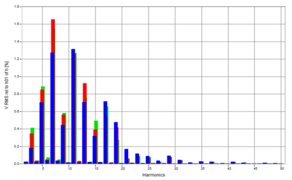
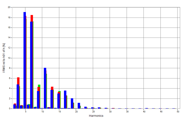
When analyzing the occurrence of higher harmonics in the network of a public building (Fig. 1), the 7th and 11th harmonics dominate, and to a lesser extent the 5th, 9th, 13th and 17th harmonics. A similar situation occurs in the current waveform (Fig. 2). Mainly there are harmonics of odd orders, up to the 19th harmonic. The next ones have a negligible impact on the voltage and current distortion.
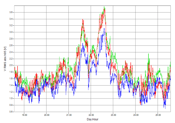
After isolating the 5th harmonic (Fig. 3), an increase in values can be observed during the weekend, when most of the installed devices are turned off. The reason for this phenomenon may be the loads which, normally working on working days, additionally compensate for the 5th harmonic, or on these two days equipment was used whose characteristic harmonic is the 5th harmonic..
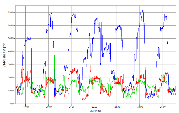
Another deviation is the occurrence of harmonic number 21 mainly in the L3 phase (Fig. 4 – blue). It means that single-phase devices are installed, which generate this harmonic characteristic.
Forecasting of higher harmonics occurrence
To predict the behavior of higher harmonics, one type of statistical series, which is a time series, can be used. It can be defined as a sequence of observations of a phenomenon in subsequent units of time, e.g. years, quarters, months.[14-17] The phenomenon under consideration may be subject to certain regularities, the detection and description of which is the purpose of time series analysis.[16]
The basic functions of time series include::
The regression function described by the formula:

The difference between empirical and model values described by the formula:

Seasonality index described by the formula:

Determination of modified theoretical values taking into account seasonality, described by the formula:

Forecasting described by the formula:

Based on the observations of harmonic variability, the type of seasonality can be identified. In the example discussed, it has an additive character.
The figures below show example charts of the seasonality function for a public building (Fig. 5).
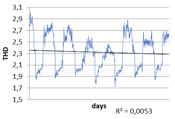
Analyzing the charts (Fig. 5), it can be observed that the seasonality function has a positive trend. The measure of model fit is low. This is most likely due to the nature of the coefficient changes.
By determining the basic functions of time series in accordance with the relationship (1) and (5), the regression function and forecasting take the form:

The forecast increase in the occurrence of harmonics for a period of 24 months is 1.67.
Summary
The analysis of electricity quality parameters did not reveal any exceedances. It can be noticed that in both current and voltage waveforms there are higher harmonics that distort the signal. Odd harmonics predominate to the greatest extent, the 5th, 7th, 11th and 13th harmonics are characteristic of the voltage signal, and to a lesser extent the 3rd, 9th, 13th and 17th harmonics. The current waveform mainly contains the 5th and 7th harmonics. It can therefore be concluded that these are characteristic harmonics (5 and 7) of devices located in the building, such as:
• converter devices, i.e. computer power supplies prevailing in the building, as well as LED light sources. Their construction is based on semiconductor elements such as thyristors, diodes, etc. whose task is to adjust the network parameters so that the devices work properly, i.e. converting the alternating voltage into direct current and reducing its value for proper power supply,
• as well as high-power motors used in elevator drives.
When taking into account the type of facility that is a public building, the best solution would be to use an active filter to reduce the number of higher harmonics. This is justified by the positive seasonality trend. The work system in the analyzed facility proves that the building is continuously equipped with the latest equipment containing converter elements,
REFERENCES
[1] Kowalski.Z.: Power quality. Monographs of the Lodz University of Technologyj. Łódź 2007.
[2] Fuchs E., Masoum M.: Power Quality in Power Systems and Electrical Machines. Elsevier Inc., 2008. 205
[3] Z. Hanzelka, Quality of electricity supply, Krakow: Publisher
AGH Krakow, 2013
[4] K. Kuczyński, J. Szymański,Harmonic compensation – introduction to active filters, elektro.info 12/2020
[5] https://jeanmueller.pl/filtry-aktywne-wyzszych-harmonicznych/
[6] A.Klajn, M.Bątkiwicz-Pantuła, Application Note – Standard EN 50 160: Voltage characteristics of electricity supp
[7] EN 50160:2010. Voltage characteristics of electricity supplied by public electricity networks.
[8] Decree of the Minister of Climate and Environment of March 22, 2023 on detailed conditions for the operation of the electricity system (Dz. U. 2023 r., 819).
[9] Heping P., Wenxiong M,. Yong W., Le L., Zhong X. Identification method for power quality disturbances in distribution network based on transfer learning, Archives of Electrical Engineering , 2022 , vol. 71 , No 3 , 731-754
[10] Baggini A., Hanzelka Z., Voltage and Current Harmonic, Handbook of Power Quality, Whiley, 2008, 200-236
[11] EN 61000-4-30:2015 Electromagnetic compatibility (EMC) – Part 4-30: Testing and measurement techniques – Power quality measurement methods
[12] Chojnacki A. Ł., Kończak Z., Seasonality and causes of damage to power distribution networks, Elektro.info 7-8/2023, 2023
[13] Golkhandan, N.H.; Ali Chamanian, M.; Tahami, F. A New Control Method for Elimination of Current THD under Extremely Polluted Grid Conditions Applied on a Three Phase PWM Rectifier. In Proceedings of the INTELEC, International Telecommunications Energy Conference (Proceedings), Turino, Italy, 7–11 October 2018
[14] Kot S., Jakubowski J., Sokołowski A., Statistics, Difin, Warszawa 2011
[15] Sokołowski A., Time series analysis and forecasting, Statistics in research and teaching statistics, Statsoft, Kraków 2010
[16] Ręklewski M. Descriptive statistics. Theory and examples. State Vocational University in Włocławek, Włocławek 2020
[17] IEA,Management Seasonal and Interannual Variability of Renewables , IEA, Paryż https://www.iea.org/reports/managing-seasonal-andinterannual-variability-of-renewables, Licencja: CC BY 4.0, 2023
[18] Kuśmierek Z.: Harmonics in power systems, Przegląd Elektrotechniczny, 82 (2006), nr 6, 8-19
[19] PN-EN 61000-3-11:2020-01 Electromagnetic compatibility (EMC) – Part 3-11: Limits – Limitation of voltage variations, voltage fluctuations and flicker in public low-voltage power
supply networks – Equipment with a nominal current < or = 75 A subject to conditional connection
[20] PN-EN IEC 61000-3-2:2019 Electromagnetic compatibility (EMC) – Part 3-2: Limits – Limits for harmonic current emissions (phase supply current of the receiver ≤ 16 A)
Authors: dr inż. Marta Bątkiewicz-Pantuła, Wrocław University of Science and Technology, Faculty of Electrical Engineering, Power Electrical Department, ul. Wybrzeże Wyspiańskiego 27, 50-370 Wrocław, e-mail: marta.batkiewicz-pantula@pwr.edu.pl
Source & Publisher Item Identifier: PRZEGLĄD ELEKTROTECHNICZNY, ISSN 0033-2097, R. 101 NR 2/2025. doi:10.15199/48.2025.02.52

