Published by Krzysztof BOLEK1, Mirosław CZECHOWSKI2, Tymoteusz NACZYŃSKI3, Politechnika Krakowska (1), Politechnika Krakowska (2), Politechnika Krakowska (3),
ORCID: 1. 10009-0005-4756-8327.; 2. 0000-0001-5093-4870; 3. 0000-0003-0323-5393
Abstract. This article describes the concept of building an inexpensive power supply for testing devices in Poland whose destination is the USA. Firstly, the power grid configurations used in the USA is described. Secondly, the concept of power supply that provide required voltage parameters 60Hz / 110V out of European 50Hz / 230V is described. Next parts of the paper treat about lab testing of the device when it is not loaded and when it is loaded with required by client 2,5-3 kW.
Streszczenie. W artykule opisano koncepcję budowy niedrogiego zasilacza do testowania urządzeń w Polsce, której przeznaczeniem są USA. W pierwszej kolejności opisano konfiguracje sieci elektroenergetycznych stosowane w USA. W drugiej kolejności opisano koncepcję zasilacza zapewniającego wymagane parametry napięcia 60 Hz / 110 V z europejskich 50 Hz / 230 V. Kolejne części artykułu dotyczą badań laboratoryjnych urządzenia w stanie nieobciążonym oraz pod obciążeniem wymaganą przez klienta mocą 2,5-3 kW. (Podłączanie urządzeń europejskich w USA)
Keywords: Single and three phase connections used in the USA, Voltage inverter, Frequency inverter.
Słowa kluczowe: Połączenia jedno- i trójfazowe stosowane w USA, Przetwornica napięcia, Przetwornica częstotliwości.
Introduction
Like all over the world, electrical appliances in the United States (USA) are powered by single- or three-phase sinusoidal current. Three-phase sinusoidal current, as in every country, is produced by electricity generators in power plants. Only the AC pulsation frequency here is different from the European 50 Hz, and is 60H z. Single pole generator turbines rotate at 3600 rpm. In Europe, 3000 rpm was adopted. As elsewhere in the world, three-phase sinusoidal current is distributed over longer distances by high-voltage lines. Three-phase sinusoidal current is also distributed via medium voltage lines to industrial plants, larger individual energy consumers and housing estates. Here the resemblance to the European, American electricity system ends.
For domestic purposes, including small businesses and even large rural farms, the US uses a completely different power connection from Europe. Medium voltage three-phase, or even sparingly interphase, or single-phase, is distributed along American roads and streets most often on wooden poles. Near the property, on the street pole, a single-phase transformer is installed, lowering the interphase, or single-phase medium voltage to a low voltage – designed to power one or several local consumers, or a local low voltage lines, that run along the street for a short distance. The transformer has a secondary winding 240 V, in the middle with a grounded detachment, realizing a two-phase power supply with a voltage of 120/240 V, with phases shifted by a 90-degree angle.
It should be added that large multi-family buildings, office buildings or large industrial facilities are directly powered by a three-phase medium voltage connection, and in a local three-phase transformer lowering this medium voltage, to three-phase low voltage, secondary winding connects in a star configuration with a central point grounded, where the phase voltage is 120V, and the interphase voltage reaches not 240 but 208V. This voltage is accepted by most 240V receivers available on the North American market [1].
As already mentioned in the USA, typical low-voltage systems (500V AC and less) are single-phase and three-phase circuits, with a frequency of 60 Hz. The connection systems of single- and three-phase installations used in the USA differ significantly from the standards adopted in Poland.
In the USA, the systems are divided into:
1) Single-phase sinusoidal current circuits:
a) 120/240 V, 3-wire, single phase.
b) 240 V, 2-wire, single phase.
c) 120 V, 2-wire, single phase
d) 480 V, 2-wire, single phase
2) Three-phase systems are divided into:
a) 208Y/120 V, 4-wire, 3-phase.
b) 480 Y/277 V, 4-wire, 3-phase.
c) delta connection, where voltage is 240 V, 277 V, 480 V or 600 V
d) delta connection, 3-phase, 3-wire, triangle with “corner” grounding (line grounding)
e) delta connection, 3-phase, 4-wire, 120/240 V triangle, with one phase grounded at the center point;
f) open delta, 3-phase, 4-wire with two transformers[2]
In single-family houses, protection with 2×60 A, 2×100 A, 2×200 A fuses is used. In work places, the values of the safety fuses are very different. but in most cases the values of the main safety fuses are larger and are above 2×100 A, or 3×100 A. It should also be reminded, that electric motors imported from the EU will have a higher rotational speed which is related to the US network frequency of 60 Hz.
U. S. single-phase and three-phase power systems must comply with Article 210 of the National Electric Code (NEC) [3]. Article 210 of the NEC includes general requirements for branch circuits. When designing special purpose branch circuit, Article 210 is always applied, with some modifications or additions (references to specific devices) [4]. The National Electric Code (NEC) marked as ANSI/NFPA 70. Is the standard adopted in the United States (USA) for the safety of electrical wiring and electrical equipment installation? The NEC is developed by the Committee on National Electrical Code associated with NFPA, which consists of 19 code making panels and Technical Correlation Committee. The work on the NEC is sponsored by the National Association for Fire Protection. NEC has been approved as a US national standard by the American National Standards Institute (ANSI).
The concept of creating a power supply prototype
For the purpose of testing machinery built in Poland, whose destination is North America, a prototype power supply (Fig. 1.) was developed and built so that it simulates the parameters of the US power grid. Machines built for European market, that are based on devices powered by sine wave voltage with frequency of 50Hz, must be tested before release. One of the tested devices are drives of vibrating feeders [5], for which frequency and voltage waveform are important for correct operation. Machinery produced for North America market must be tested as well. For this purpose, a company producing machines for the US market built a prototype power supply (Fig. 1.), which simulates the parameters of a low-voltage power supply grid in the USA [6].
The prototype power supply consists of two elements:
• DC power supply ZJIVNV S-3000-110 (Fig 1. pos.1);
• Pure sine wave inverter Belevschi 8000W (Fig 1.pos. 2.).
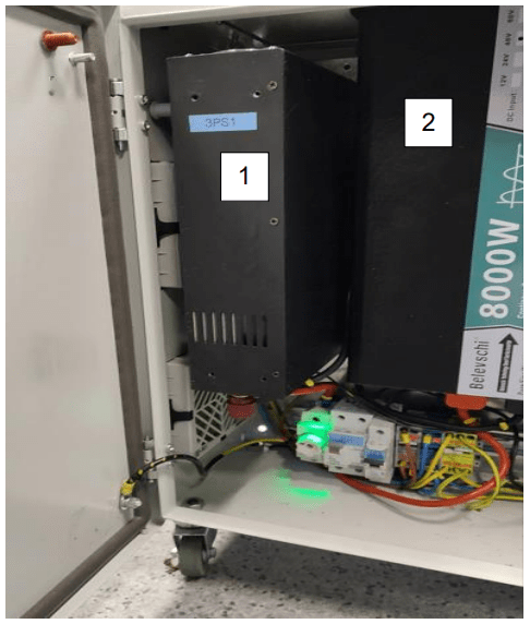
The other components are electrical protection devices and cooling fans. The power supply (Fig. 1. pos. 1) was selected to meet the requirements of the industry for machines produced for the US market, that is estimated as 2.5 – 3 kW.
The inverter (Fig 1. pos. 2) was oversized for a reason of possible future increase of the power supply and was chosen as the smallest of the type series available at the manufacturer. Oversizing the inverter was also to ensure a clean sine wave, by guaranteeing that the inverter is not overloaded with too much power consumption, power level close to a rated power.
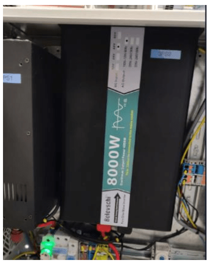
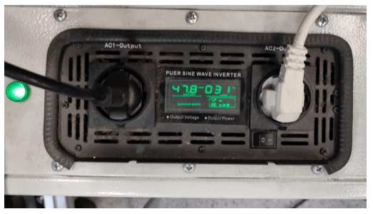
The manufacturer of the Belevschi 8000W voltage inverter (Fig. 2.) declares pure sine wave.
Laboratory testing of power supply prototype
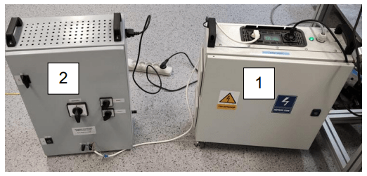
For the purpose of verifying the declaration of the manufacturer of the inverter(Fig. 3. pos. 1.), a test stand that consists of a resistive load (Fig. 3. pos. 2) and a measuring system (Fig. 4. ) was created.
Measurement was performed with digital oscilloscope RIGOL MS5104 (Fig. 4. pos. 1) via differential probe TT-SI 9002_TESTEC_1:20/1:200_25 MHz (Fig. 4. pos. 2) set to the attenuation range 1:200, and the oscilloscope read was multiplied appropriately, so that actual voltage was shown on the oscilloscope. The oscilloscope sampled 20 million samples per second during all the tests performed.
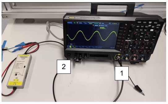
In order to verify the manufacturer’s declaration, voltage waveform (Fig. 4.) that was received at the output of the inverter, has been examined (Fig. 1.).
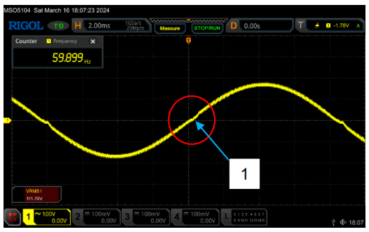
As it can be seen on the Fig. 5., sinusoidal waveform is “clean”. The stable frequency of 60 Hz RMS and voltage of about 115 V is archived. In addition, it can be noticed that the inverter has many “steps” (fig. 6) thanks to which it is able to reproduce the sinusoidal voltage waveform so well. There is a slight distortion when passing through zero (Fig 5. pos. 1).
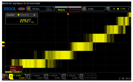
On the above waveform (Fig. 6.), which is a section of the waveform shown in Fig. 5., the switching of successive stages of the voltage inverter is clearly visible. The number of these steps in the cycle corresponds to the number of cycles by which one period of output sine wave voltage has been divided. The more cycles have been performed, the more accurate is the mapping of the perfect sine wave is achieved. Today IGBT transistors for low power can switch with frequencies up to 50 kHz.
The prototype power supply loading
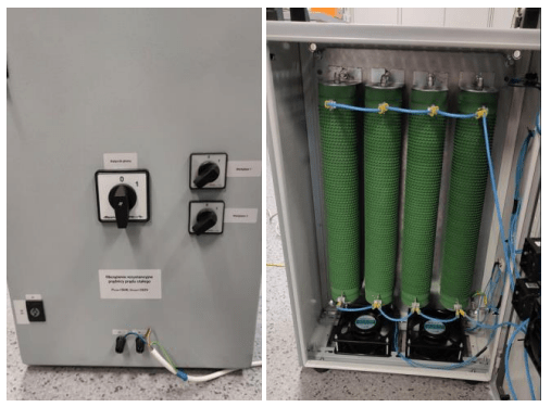
A resistive load has been connected to the inverter (Fig. 7.) of parameters of Pmax = 5 kW, Umax = 250 V. With the power supply of 120 V RMS, the power of the load should be about half of the rated power expected for European power supply system voltage of 230 V.
The purpose of this test was to check whether the inverter produces the pure sine under a load of about 2.4 kW. The load value read from the inverter display was 31% of the rated load of 8 kW, which is about 2.4 – 2.5 kW.
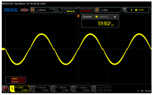
The loaded inverter also generates a sufficiently clean sinusoidal waveform (Fig. 8.). Slightly increased RMS voltage to 119V, but it is still normal (Fig. 9.).
It should be remembered that the voltage inverter is oversized in correlation to the DC power supply, so there are no obstacles in maintaining a “nice” sinusoidal voltage waveform.
Conclusion
The prepared prototype successfully simulates the parameters of the power grid such as can be found in the American power supply system. Laboratory tested power supply transforms our native 50Hz and 230V voltages to American standard 60Hz and 120V with high accuracy. Minor deviations of parameters recorded by the measuring apparatus, both in rated condition and under load, fall within the reasonable margin and result from the imperfections of the devices used for the construction of the system. This quality can be improved by using better but also more expensive inverters, however, it should be considered that the system is intended to power industrial equipment and not laboratory equipment, which could require greater accuracy. Industrial devices must be characterized by a certain tolerance to power conditions, because the power grid is a living organism that constantly remains in a dynamic state. However, the presented system provides sufficient power reserve of the inverter, obtained by oversizing the inverter in relation to the power supply, so that even at the full assumed load of the power supply, approx. 3 kW, the inverter had no problems with maintaining the parameters. And as it has been shown, such loaded circuit further maintains the parameters of the sine wave of the supply voltage at a very same level, as unloaded circuit. Considering that one of the aims of the construction of the system was to keep its production costs at a fairly low level, which necessarily had to translate into the quality of the selected elements, it should be considered that the obtained voltage parameters at the output of the system are completely sufficient, and the system successfully serves the purpose for which it was built.
REFERENCES
[1] ELHU.pl “Zasilanie elektryczne w USA,” USA Power | ELHU, dostep kwiecień 2024.
[2] EEPOWER., National Electrical Code Basics: Branch Circuits Part 1, https://eepower.com/technical-articles/nationalelectrical-code-nec-basics-branch-circuits-part-1/, dostep kwiecień 2024.
[3] Article 210, “Branch Circuits. Part I. General Provisions,”, Based on the 2023 NEC, Article 210 |(thenecwiki.com), dostep kwiecień 2024.
[4] Mark Lamendola, “National Electrical Code Articles and Information. National Electrical Code Top Ten Tips: Article 210 – Branch Circuits,”, Based on the 2023 NEC, dostep kwiecień 2024.
[5] INWET, “Maszyny wibracyjne – podajniki wibracyjne,” https://inwet.eu/maszyny-wibracyjne/podajniki-wibracyjne/, dostep kwiecień 2024.
[6] Robert Seitz, PE, “Electrical design guide for zone classified areas,” Material IEEE Paper No. PCIC-2005-6
Authors: Mgr. inż. Krzysztof Bolek, Politechnika Krakowska Wydział Inżynierii Elektrycznej i Komputerowej, ul Warszawska 24, 31-155 Kraków, E-mail: krzysztof.bolek@doktorant.pk.edu.pl; Mgr. inż. Mirosław Czechowski, Politechnika Krakowska Wydział Inżynierii Elektrycznej i Komputerowej, ul Warszawska 24, 31-155 Kraków, E-mail: miroslaw.czechowski@doktorant.pk.edu.pl; Mgr. inż. Tymoteusz Naczyński, Politechnika Krakowska Wydział Inżynierii Elektrycznej i Komputerowej, ul Warszawska 24, 31-155 Kraków, E-mail: tymoteusz.naczynski@doktorant.pk.edu.pl.
Source & Publisher Item Identifier: PRZEGLĄD ELEKTROTECHNICZNY, ISSN 0033-2097, R. 101 NR 1/2025. doi:10.15199/48.2025.01.17

