Published by 1. Raghad Adeeb Othman1, 2. Omar Sh. Alyozbaky2,
Department of Electrical Engineering, College of Engineering, University of Mosul, Iraq (1,2)
ORCID: 1. 0000-0001-5875-9210; 2. 0000-0002-9735-1469
Abstract. Ever increasing electricity demand as well as the rapid depletion of fossil fuels have increased the need for hybrid power systems that integrate distributed energy resource (DER) systems; such as solar photovoltaic (PV) systems and battery storage systems; with electrical grids. Therefore, this present study used MATLAB/Simulink to demonstrate the ability of DER inverters to provide reactive power that regulates grid voltage, decreases the total harmonic distortion (THD), decreases the amount of active power lost, and improves the capacity and power quality of a modified IEEE 13-bus test system. The study found that the injection/Absorption of the reactive power from a 400KW (PV-Battery) system in bus 675, 500KW (PV-Battery) system in bus 671, and 200 KW.h battery storage system in bus 634 decreased the power output of the main generator by 24.6%. When used in situ, the reactive power capability of the DER inverters significantly improved the voltage while an injection of reactive power decreased the THD voltage of bus 675 phase B by 81.26% when absorbing reactive power as well as decreased active power losses.
Streszczenie. Stale rosnące zapotrzebowanie na energię elektryczną oraz szybkie wyczerpywanie się paliw kopalnych zwiększyły zapotrzebowanie na hybrydowe systemy zasilania, które integrują systemy rozproszonych źródeł energii (DER); takie jak systemy fotowoltaiczne (PV) i systemy magazynowania baterii; z sieciami elektrycznymi. Dlatego w niniejszym badaniu wykorzystano MATLAB/Simulink do wykazania zdolności falowników DER do dostarczania mocy biernej, która reguluje napięcie sieci, zmniejsza całkowite zniekształcenia harmoniczne (THD), zmniejsza ilość utraconej mocy czynnej oraz poprawia wydajność i jakość mocy zmodyfikowany system testowy IEEE 13-bus. Badanie wykazało, że wtrysk/pobór mocy biernej z systemu 400KW (PV-Battery) w magistrali 675, 500KW (PV-Battery) w magistrali 671 i 200KW.h systemu magazynowania baterii w magistrali 634 zmniejszyło moc moc głównego generatora o 24,6%. W przypadku zastosowania in situ, moc bierna falowników DER znacznie poprawiła napięcie, podczas gdy wprowadzenie mocy biernej zmniejszyło napięcie THD szyny 675 fazy B o 81,26% podczas pochłaniania mocy biernej, a także zmniejszyło straty mocy czynnej. (Nowatorska metoda poprawy jakości energii za pomocą systemu hybrydowego)
Keywords: Power Quality; PV System; Battery Storage Systems; THD; Distributed Generation; Reactive power Capability.
Słowa kluczowe: Jakość energii; System fotowoltaiczny; Systemy przechowywania baterii; Moc bierna Zdolność.
Introduction
Rapid population growth and economic development have put the power industry under significant pressure to generate more electricity to meet increased demands. However, the amount of energy that can be supplied to consumers depends on the centralised power generation system, which typically consists of conventional power generators. Centralised power generation systems are also plagued with drawbacks; such as the high costs of fossil fuels [1], the loss of energy during transmission and distribution, and the depletion of reserves of conventional energy sources which, in turn, increases environmental concerns. Therefore, pollution and global warming, the volatility of oil prices, and the increased global demand for electricity create an urgent need to identify alternative sources of energy that are more sustainable than traditional energy sources [2]. As such, new concepts and strategies for planning and operating energy systems must be developed. This has caused many organisations to adopt distributed energy resource (DER) systems, which include Distributed Generation (DG) systems and Energy Storage Systems (ESS); to address these issues [3].
Distributed energy sources are alternative or renewable energy sources (RES); such as photovoltaics (PV), wind, biomass, and hydropower; that are beginning to play an increasingly vital role in the emerging electrical power systems that power residential and commercial facilities [4]. However, due to technological and economic constraints, a sudden increase in energy demand, and a lack of distribution infrastructure, power companies have taken to decentralizing their electrical systems and integrating renewable DG systems to their distribution network by connecting them directly at or near load points. This has been found to provide economic, environmental, and technical benefits to consumers and distribution systems alike [5].
As the intermittent nature of RES systems renders energy production from a single source unreliable, it has caused hybrid renewable energy source (HRES) systems; which rely on more than one energy production system; to grow in popularity. The reliability of HRES systems can be further increased by integrating ESS; such as batteries and fuel cells; to meet load demands at periods when RES systems cannot produce sufficient power [6].
Power converters are typically used to connect a DER system to a conventional network as they offer significant advantages; such as optimal operation and flexible control; while DG systems provide benefits; such as voltage support, reduced losses, higher power quality, system reliability, and opportunities to sell the extra energy to offset consumer electricity bills [7]. Nevertheless, the integration of power converters with DG systems into electrical grids creates a host of problems in terms of protection, safety, and total harmonic distortion (THD) [8]. As a RES inverter system can control reactive power, it can also be used as an in situ rapid response mechanism in areas with high levels of PV penetration. This satisfies the primary goal of a power distribution network; which is to reduce power loss and to increase the efficiency and reliability of the transmission process; to provide good quality electricity to consumers [9] and to overcome voltage regulation issues to enhance network stability [10].
This present study investigated the ability of the RES inverter to inject and absorb reactive power to a modified IEEE 13-bus test electric power system in different operating modes. The purpose of this study was to highlight the importance of effective and rapid interactions when controlling the electrical variables caused by the reactive power flows that a power distribution system requires in relation to the distribution network requirements and PV energy availability. Also examined were the ability of these effective and rapid interactions as well as the use of local power compensation controls to improve the voltage profile of each bus to provide stability, liberate the capacity of lines and equipment, and improve the power quality of the network.
The Ability of the PV Inverter to Inject and Absorb Reactive Power
A PV inverter can provide reactive power without decreasing active power output. Therefore, an important shift will drive these systems so long as reactive power is injected correctly and dynamically supplied when it is needed the most, near loads. According to the Oak Ridge National Lab, distributed voltage controls are far more superior than centralised voltage controls as distributed voltage regulation creates an efficient system without power failures. Advanced inverters are also less expensive than traditional voltage-regulation options. Therefore, systems and customers who adopt this technology will only stand to benefit. Some of the several potential advantages of generating reactive power with a PV inverter system includes [11]:
• Reflectors that can generate both capacitive reactive power and inductive reactive power.
• The generated active power can be adjusted accurately and quickly when needed.
• Additional investments are not required when using inverters.
Apart from that, inverters can, depending on climate conditions, operate as a reactive power source when solar radiation levels are low. This improves solar PV energy utilisation and eliminates the need for reactive power compensation, making it cost effective [12].
As seen in Fig. 1. and according to Eqs. (1), the amount of reactive power that an inverter can generate for a network depends on the apparent power of the inverter [13]:
Where: 𝑆inv. is the rated power of the inverter, 𝑃pv is the instantaneous PV power of the PV Array, 𝑄inv. is the reactive power of the inverter, and QMAX is the reactive power limit of the inverter when supplying active power 𝑃pv [13].
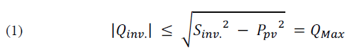
An analysis of the reactive power capability of the inverter seen in Fig. 1 indicated that the inverter was able to inject reactive power (+Q) when the network failed to generate sufficient reactive power. The inverter was also able to absorb reactive power (-Q) to decrease the voltage of the grid.

Hybrid System Modelling
A hybrid power system consisting of RES systems; specifically, a (PV-battery) system and a (battery-grid) system; was modelled and connected to a modified IEEE 13-bus test system to examine the ability of the inverter to inject and absorb reactive power in the unbalanced of a three-phase system.
A. Modified IEEE 13-bus test system
This small test feed unit, to which large loads are attached, has very interesting characteristics. The voltage level of a short and sufficiently loaded network was 4.16 kV. The system comprised 13 buses, 10 overhead and underground transmission lines, a Y 115/4.16 kV transformer, a voltage regulating unit, a voltage generating unit, a YY 4.16/0.480 kV internal transformer, and two parallel capacitances [14]. While modelling the distribution networks, it was discovered that removing the voltage regulator and replacing it with a swing generator of specific characteristics simplified the model without sacrificing accuracy. Therefore, the voltage regulator was removed from the IEEE 13-bus distribution feeder as a renewable DG system can alter voltage levels. The voltage of the generator was set at 4.16 KV and connected directly to the distribution lines. Parallel capacitances were also excluded from the design as shown in Fig. 2.

B. Modelling the Components of the (Photovoltaic Battery) System
Photovoltaic array
Two (PV-battery) systems were designed. The first system consisted of four parallelly connected PV arrays to generate 400 KW of active power while the second consisted of five parallelly connected PV arrays to generate 500 KW of active power. The PV arrays were module-type SunPower® SPR-305E-WHT-D (305W) solar panels that each generate 100 KW of electrical power. All the PV arrays were set to operate under standard test conditions (STC), which was 1000 W/m2 of solar radiation at 25°C.
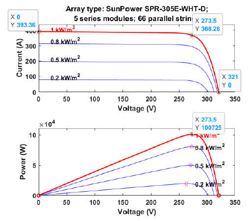
Fig.3. shows the (I-V) and (P-V) of the proposed PV model at different light radiation ratios and 25°C as well as the design of the PV system.
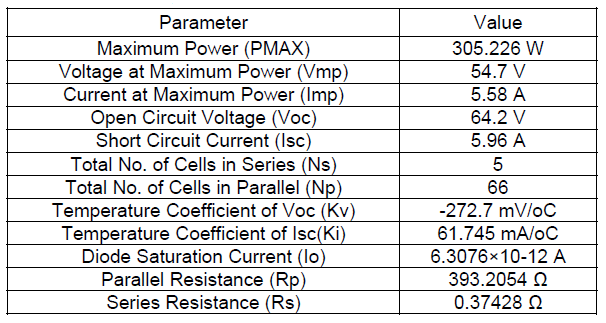
As seen in Fig. 3., variations in solar radiation mostly affected PV current and least affected voltage. Meanwhile, an increase in solar radiation increased the amount of PV power generated as the amount of current had increased. The maximum power point (MPP) obtained at 1000 W/m2 radiation was 100.725 KW. The PV arrays were set to operate under STC, which was 1000 W/m2 of solar radiation at 25°C as shown in Table 1.
Table 1. The SunPower® SPR-305E-WHT-D (305W) PV Module
The Battery Model in the (PV-Battery) System
A battery was used to store and supply energy to the network. It was charged by the power generated by the PV array and discharged to help provide the power required to operate a load when the PV array failed to produce sufficient power.
Battery size is important as it needs to provide maximum backup power to compensate for a lack of solar generation in the event of low or no radiation. The MPP of the PV arrays used in this present study was 100 KW at STC. Therefore, a battery that could provide this amount of power to loads for a maximum of one hour in an emergency; such as a lack of radiation; was chosen.
A (lithium-ion) battery, with a maximum current discharge capacity of 300 A, was selected to provide one hour of backup power in the event of zero radiation. Table 2 shows the values of the proposed battery design.

Controlling the charging and discharging of the battery in the (PV-battery) system
In the (PV-Battery) system, the battery was charged by the power generated by the PV array and acted as an alternative source of energy for the PV system when the level of radiation was low. The battery operating modes were determined by the amount of radiation in the PV system and the state of charge (SOC) of the battery. The maximum and minimum SOC limits were set at 80% and 20%, respectively. This present study used the lowest photoelectric radiation value; i.e. 300 W/m2; to prevent the battery from deteriorating and to prolong its life [15] [16]. Fig. 4. depicts the charging and discharging patterns of the battery of the (PV-battery) system.
Table 2. The Battery of the (PV-Battery) System

C. Modelling the components of the (battery-grid) system
The Battery Model in the (Battery- Grid) System
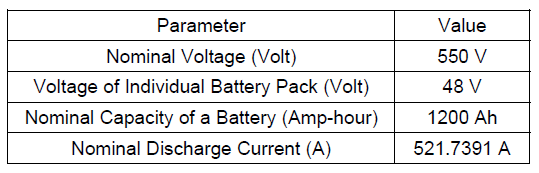
A (lithium-ion) battery was chosen to store the energy. In the battery-grid system, the battery was charged by the power generated by the main generator of the electric power system and discharged when needed to provide additional power when the load was high. A 200 KW.h battery with a total capacity of 1200 Ah was selected to provide standby power for a maximum of three hours when loads exceeded the rated value. Table 3 provides the values of the proposed battery design.
Table 3. The Battery of the (Battery-Grid) System
Controlling the charging and discharging of the battery in the battery-grid system
When the battery was connected to the network to serve as a source of electrical power via the inverter, it was charged by the power generated by the electrical power system.
However, the operating mode depended on the load required and the SOC of the battery. Fig. 5. depicts the charging and discharging patterns of the battery connected to the network.
As seen in Fig. 5., the load supplied by the electrical power system was stable. When the load demand was high, if the battery had been charged, it provided the load with the additional power necessary to operate. Meanwhile, when the load demand was low, the excess power of the network was used to charge the battery if it needed to be charged.
Simulation and Results
A hybrid system shown in Fig. 6.; which connected a 500 KW (PV-battery) system to bus 671, a 400 KW (PV-battery) system to bus 675, and a 200 KW.h battery storage system to bus 634 of a modified IEEE 13-bus test system in battery isolation, battery charging, and battery discharging modes; was used to demonstrate the feasibility of injecting and absorbing reactive power to improve power quality by decreasing the need for active power from the central generator, increasing and decreasing the voltage, and decreasing the THD of the voltage and current. This present study discusses the effect of these hybrid systems on the point of common coupling (PCC); where a RES system connects to the electric power system; as well as their effect on the IEEE buses that are locally linked to the RES system. MATLAB® Simulink was used to execute the computer simulations.


Mode 1: Battery Isolation
This mode occurs when the PV arrays of both the (PV-battery) systems operate at STC and the batteries are fully charged. Meanwhile, in a (battery-grid) system, this mode occurs when the load operates normally and the battery is full charged.
As shown in Fig. 7., The results indicate that when PV arrays operate at STC and at a unity power factor (UPF), they generate maximum active power without generating reactive power. Furthermore, isolating the battery of the (battery-grid) system at UPF means that it does not generate any active or reactive power. This is evidenced by distortions in the voltage and current.
The voltage increased at the PCC when both the (PV-battery) systems injected reactive power into the electric power system. Even in battery isolation mode, the voltage increased at the PCC when the (battery-grid) system injected reactive power into the electric power system. Therefore, an injection of reactive power from a RES system to an electrical power system causes the voltage at the PCC and DC-Link to increase. Hence, the hybrid systems failed to achieve the correct isolation pattern for the battery.
The total harmonic distortion of voltage (THD-V) was low at the PCC of buses 671 and 675 when reactive power was injected. However, the total harmonic distortion of current (THD-I) decreased at the PCC of bus 671 when 201.62 KVAR of reactive power was injected at a rate of 13.37%. It also decreased the THD-I at the PCC of bus 675 by increasing reactive power injection.
The absorption of reactive power by the electrical power system caused the voltage to decrease at all the PCC. The absorption of reactive power by the RES systems caused the THD-V to decrease at the PCC of busses 671 and 675 and the THD-I to decrease at all the PCC as the amount of reactive power absorbed increased.


Mode 2: Battery Charging
This mode occurs when the PV arrays of both the (PV-battery) systems operate at STC and the batteries are not charged (SOC = 10%). Meanwhile, in a (battery-grid) system, this mode occurs when the load is 50% of normal operating loads and the SOC of the battery is 10%. Table 4 provides the amount of voltage and current required to charge the batteries of the RES systems connected to electrical power systems.
As seen in Fig. 8., the power factor (P.F) is negative indicating that power flows from the electrical power system to the (battery-grid) system. However, an injection of reactive power into the electrical power system increased the voltage at the three PCC with RES systems, where the voltage increased by 0.54% at the PCC of bus 671 when 301.94 KVAR of reactive power was injected. It also increased the THD-V at the PCC of buses 671 and 675. Although the THD-V at the PCC of bus 634 also increased, it decreased as the amount of reactive power increased. Meanwhile, the THD-I at the PCC of buses 671 and 675 decreased as the amount of reactive power increased while it increased at the PCC of bus 634 when 47.22 KVAR of reactive power was injected.
Absorbing reactive power from the three RES systems decreased the voltage at the PCC with the electrical power system. The THD-V at the PCC of bus 634 decreased by 5.2% when absorbing 92.13 KVAR of reactive power. Meanwhile, the THD-I marginally decreased at the PCC of bus 671 when absorbing 298.7 KVAR and decreased at the PCC of buses 675 and 634 by increasing the absorption of reactive power.
Table 4. The Voltage and Current Required to Charge the Batteries of the RES Systems
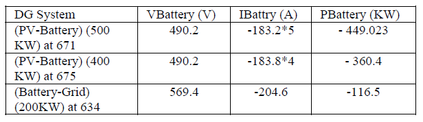
Table 5. The Voltage and Current Discharge of the Batteries of the RES Systems

Mode 3: Battery Discharging
This mode occurs in both the (PV-battery) systems when the SOC of the battery is 70% and the irradiance is 0%. Meanwhile, in the (battery-grid) system, this mode occurs when the normal operating load at bus 634 increases by 50% and the SOC of the battery is 75%. Table 5 shows the amount of power generated by the batteries in the battery discharging mode.
As seen in Fig. 9., an injection of reactive power increased the voltages at all the PCC. This decreased the THD-V at the PCC of buses 671 and 675 and increased the THD-V at the PCC of bus 634 by 10.73% when the amount of reactive power injected exceeded 109.74 KVAR over its value at UPF. The THD-I at the PCC of buses 671 and 675 increased while it decreased by 18.7% at the PCC of bus 675 when the amount of reactive power injected was 241.69% higher than its value at UPF.
Absorbing reactive power from the electrical power system decreased the voltage and increased the THD-V at the PCC of the three buses. Meanwhile, the THD-I decreased at the PCC of bus 671 and decreased by 25.43% at the PCC of bus 634 but increased by 16.6% at the PCC of bus 675 when 238.43 KVAR of reactive power was absorbed.
The effect of reactive power on buses 671, 675, and 634
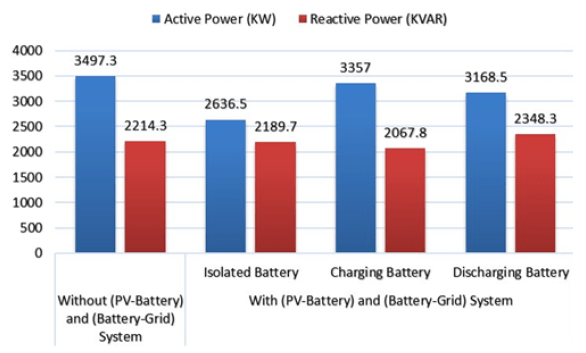
Integrating the three RES systems with the electrical power system at buses 671, 675, and 634 decreased the amount of energy that the main generator needed to generate to operate the loads of the electrical power system. The amount of active power that the main generator needed to generate in bus 632 in battery isolation mode at UPF decreased by 24.6%; from 3497.3 KW to 2636.5 KW; when RES systems were not connected (Fig. 10.).
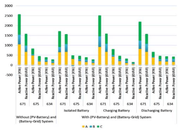
Connecting a RES system to the electrical power system effectively decreased the amount of electric power supplied from bus 632 to buses 671, 675, and 634, especially in battery isolation mode. The amount of active power supplied to the bus exceeded the amount of active power that the batteries contained in charging and discharging modes. Active power was supplied to buses 671 and 675 at a rate of 33.4% and 45%, respectively, in battery isolation mode with UPF in comparison to no RES systems. It is noteworthy that the active power flowed in reverse in phase B of bus 675 as the PV system generated more power than a common load required in battery isolation mode (Fig. 11.).


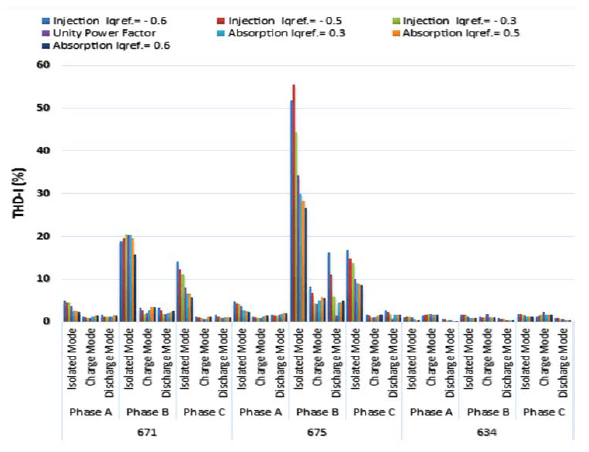
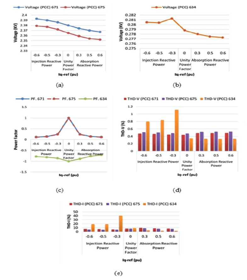
Fig.12. depicts the effect of reactive power on the voltages of buses 671, 675, and 634. The voltages increased as the amount of reactive power injection increased and decreased when reactive power absorption exceeded its value at UPF.
The largest distortion in the voltage wave (THD-V) occurred in battery isolation mode at UPF. Therefore, reactive power has a clear effect on this mode. As seen in Fig. 13., the THD-V of buses 671, 675 and 634 decreased in phases A, B, and C when reactive power was injected.
Fig. 14. depicts the evident effects of THD-I in battery isolation mode in buses 671 and 675 due to the large amount of power supplied by the PV systems to the electrical power system. The THD-I of bus 675 in phase B increased significantly more than the other phases due to the low load and P.F of this phase. As such, the PV system would supply an excess of reactive current, which would increase the THD. Therefore, the THD-I is underestimated when reactive power is absorbed.
As seen in Fig. 15., the transmission lines linking buses 632-671, 692-675, and 633-634 experienced the highest losses in the battery charging mode. This occurred as, in this mode, most of the power generated from RES is used to charge the batteries. As such, the power flows within the transmission lines from the main power generation sources of an electrical power system to cover the load requirements of the buses. The injection of reactive power helped decrease the amount of active power losses when the amount of reactive current in transmission lines decreased but increased the amount of active power losses when reactive power absorption increased.
Conclusion
This present study highlights the need for reactive power injection via DER inverters to improve the voltage profile and power quality of distribution systems. A hybrid power system with modified IEEE 13-node test system was developed to analyses the voltage profile and active power of a system in different operating modes. Most of the DERs were linked to the electrical network with the help of electronic-electric interfaces that generate active and reactive power by properly controlling the interface of an inverter. The effect of an injection and absorption of reactive power was also examined. The voltage profile significantly improved and the THD-V and THD-I decreased when the full reactive power capacity of the DER inverter was used. The proposed model decreased the power output of the generator by 24.6% and significantly improved the in-situ voltage profile by utilising the reactive power capabilities of DER inverters. Furthermore, the THD-I decreased by 81.26% when reactive power was injected or absorbed.
Acknowledgment – Authors would like to thank Mosul University, College of Engineering, Electrical Department, for the support given during this work.
REFERENCES
[1] R. H. A. Zubo, G. Mokryani, H. S. Rajamani, J. Aghaei, T. Niknam, and P. Pillai, “Operation and planning of distribution networks with integration of renewable distributed generators considering uncertainties: A review,” Renew. Sustain. Energy Rev., vol. 72, no. May, pp. 1177–1198, 2017, doi: 10.1016/j.rser.2016.10.036.
[2] J. P. Ram, H. Manghani, D. S. Pillai, T. S. Babu, M. Miyatake, and N. Rajasekar, “Analysis on solar PV emulators: A review,” Renew. Sustain. Energy Rev., vol. 81, no. July 2017, pp. 149–160, 2018, doi: 10.1016/j.rser.2017.07.039.
[3] A. F. A. Kadir, T. Khatib, and W. Elmenreich, “Integrating photovoltaic systems in power system: Power quality impacts and optimal planning challenges,” Int. J. Photoenergy, vol.2014, 2014, doi: 10.1155/2014/321826.
[4] A. Alshahrani, S. Omer, Y. Su, E. Mohamed, and S. Alotaibi, “The technical challenges facing the integration of small-scale and large-scale PV systems into the grid: A critical review,” Electron., vol. 8, no. 12, 2019, doi: 10.3390/electronics8121443.
[5] T. Adefarati and R. C. Bansal, “Integration of renewable distributed generators into the distribution system: A review,” IET Renew. Power Gener., vol. 10, no. 7, pp. 873–884, 2016, doi: 10.1049/iet-rpg.2015.0378.
[6] R. Singh and R. C. Bansal, “Review of HRESs based on storage options, system architecture and optimisation criteria and methodologies,” IET Renew. Power Gener., vol. 12, no. 7, pp. 747–760, 2018, doi: 10.1049/iet-rpg.2017.0603.
[7] R. Tonkoski and L. A. C. Lopes, “Voltage regulation in radial distribution feeders with high penetration of photovoltaic,” 2008 IEEE Energy 2030 Conf. ENERGY 2008, no. Lv, 2008, doi: 10.1109/ENERGY.2008.4781021.
[8] M. L. Kolhe and M. J. M. A. Rasul, “3-Phase grid-connected building integrated photovoltaic system with reactive power control capability,” Renew. Energy, vol. 154, pp. 1065–1075, 2020, doi: 10.1016/j.renene.2020.03.075.
[9] K. Emmanuel, T. Antonis, Y. Katsigiannis, and M. Moschakis, “Impact of increased RES generation on power systems dynamic performance,” Mater. Sci. Forum, vol. 721, pp. 185–190, 2012, doi: 10.4028/www.scientific.net/MSF.721.185.
[10] L. B. G. Campanhol, S. A. Oliveira Da Silva, L. P. Sampaio, and A. O. Azauri, “A grid-connected photovoltaic power system with active power injection, reactive power compensation and harmonic filtering,” 2013 Brazilian Power Electron. Conf. COBEP 2013 – Proc., no. April 2016, pp. 642–649, 2013, doi: 10.1109/COBEP.2013.6785183.
[11] S. Vlahinić, D. Franković, V. Komen, and A. Antonić, “Reactive power compensation with PV inverters for system loss reduction,” Energies, vol. 12, no. 21, pp. 1–17, 2019, doi: 10.3390/en12214062.
[12] R. A. Othman and O. S. A. D. Al-Yozbaky, “Effect of Reactive Power Capability of the PV Inverter on the Power System Quality,” Indones. J. Electr. Eng. Informatics, vol. 10, no. 4, pp.780–795, 2022, doi: 10.52549/ijeei.v10i4.3913.
[13] H. Li, C. Wen, K. H. Chao, and L. L. Li, “Research on inverter integrated reactive power control strategy in the grid-connected PV systems,” Energies, vol. 10, no. 7, 2017, doi: 10.3390/en10070912.
[14] W. H. Kerting, “Radial distribution test feeders IEEE distribution planning working group report,” IEEE Trans. Power Syst., vol.6, no. 3, pp. 975–985, 1991, doi: 10.1109/59.119237.
[15] Z. Yi, W. Dong, and A. H. Etemadi, “A Centralized Power Control and Management Method for Grid-Connected Photovoltaic (PV)-Battery Systems,” arXiv Optim. Control, no. September, 2017, doi: 10.48550/arXiv.1709.09219.
[16] E. D. Kostopoulos, G. C. Spyropoulos, and J. K. Kaldellis, “Real-world study for the optimal charging of electric vehicles,” Energy Reports, vol. 6, pp. 418–426, 2020, doi: 10.1016/j.egyr.2019.12.008.
Source & Publisher Item Identifier: PRZEGLĄD ELEKTROTECHNICZNY, ISSN 0033-2097, R. 99 NR 6/2023. doi:10.15199/48.2023.06.35
