Published by Ilham RAHIMLI1, Aliashraf BAKHTIYAROV2, Gulshan ABDULLAYEVA3, Sona RZAYEVA4. Azerbaijan State Oil and Industry University
ORCID: 1. 0009-0006-1976-4475; 3. 0000-0003-0168-9623; 4. 0000-0001-7086-9519
Abstract. Despite the fact that current transformers have been used for many years in certain sections of the electrical network, in power supply, to power the circuits of an electrical measuring installation, meters, and relay automation installations, they have various disadvantages, in particular, due to a fairly high accuracy class and error when integrated with modern digital technology. Depending on the requirements for traditional current transformers, they are divided into accuracy classes, i.e. 0.2; 0.5; 1; 3; 10. It is these accuracy classes that determine the scope of current transformers (laboratory, general technical devices, relay protection, etc.).
Streszczenie. Pomimo faktu, że przekładniki prądowe są od wielu lat stosowane w niektórych odcinkach sieci elektrycznej, w zasilaniu, do zasilania obwodów elektrycznej instalacji pomiarowej, liczników, instalacji automatyki przekaźnikowej, mają one różne wady, w szczególności ze względu na dość wysoka klasa dokładności i błąd po zintegrowaniu z nowoczesną technologią cyfrową. W zależności od wymagań stawianych tradycyjnym przekładnikom prądowym, dzieli się je na klasy dokładności, tj. 0,2; 0,5; 1; 3; 10. To właśnie te klasy dokładności określają zakres przekładników prądowych (Zastosowanie optycznych czujników prądu w podstacjach elektrycznych)
Keywords: sensor, rotation angle, polarization, optical fiber material, digital substation, accuracy class.
Słowa kluczowe: czujnik, kąt obrotu, polaryzacja, materiał światłowodu, podstacja cyfrowa, klasa dokładności.
Introduction
Current transformers are one of the types of transformers used in various industries. Since the first side of the current transformer connected in series with the circuit is connected to a high current circuit, the winding of this side also consists of one or more windings with a relatively large cross section. However, unlike the first side, the second side winding consists of coils with a small cross section and is connected to low-resistance devices – ammeters, series windings of wattmeters and calculators, etc. [1].
Despite the fact that current transformers are used in various industries, they have various disadvantages. First of all, it should be noted that when connecting a current transformer or during operation, the ends of its secondary winding should in no case remain open.
Otherwise, the transformer will go into idle mode and the magnetic flux (Ø) in the core steel will increase many times. This, in turn, can lead to overheating of the core steel and damage to the secondary insulation. Otherwise, the secondary voltage may increase sharply, which is extremely dangerous for the technical personnel servicing the equipment. Given these shortcomings, the secondary winding of the transformer must be short-circuited and grounded. In connection with what has been said in Fig. 1 shows a schematic diagram of connecting a traditional current transformer (a) and its structural view (b). Indeed, in circuit (a), the ends of the secondary windings of a conventional current transformer are connected and grounded through resistors. Otherwise, these complications and dangers are inevitable.
Another disadvantage of traditional current transformers is the saturation of the steel core. Thus, during short circuits in the electrical network, as well as during switching processes, the current in the circuit increases sharply, which leads to the flow of a large amount of magnetic flux from the steel of the current transformer, and, consequently, to a distortion of the value of the induced electromotive force in the secondary circuit. This, in turn, leads to inaccurate measurements [2]. In general, the main disadvantages of the traditional current transformer are as follows:
• Absolute short circuit of the secondary winding
• Saturation of the steel core of the transformer
• Sensitivity to metrological factors and external magnetic fields
• Instability to ferroresonance phenomena
These listed shortcomings create problems when traditional current transformers work with modern digital technology. The rapid development of digital technologies makes it inevitable to create more modern and sophisticated modifications of traditional equipment used in power supply.
Problem setting
A comparison was made between traditional current transformers and optical current sensors, the parameters of the optical current sensor, the principle of its operation and its application in an electrical substation were analyzed, and it was found that optical current sensors do not have the disadvantages that traditional current transformers have. It is for this reason that in the power supply (especially in electrical substations) the process of replacing traditional current transformers with optical current sensors and the transition to digital substations is very important. Thus, in connection with the development of digital technology, optical current sensors in terms of accuracy, simplicity and safety of operation, as well as self-diagnosis, are an integral part of the transition to modern technologies in power supply [3].
The solution of the problem
The above condition ensures the reliability of the transmission and distribution of electrical energy in electrical substations. The use of optical current sensors in power supply and especially in electrical substations is very important. The advantage of this technology is mainly due to its working principle.
The principle of operation of the optical current sensor is based on the Faraday effect. In 1846, when M. Faraday studied optical and electromagnetic phenomena, it turned out that optically inactive substances have the ability to rotate the polarization plane under the influence of an electromagnetic field. In other words, due to this effect, the phenomenon of polarization (electronic polarization) occurs in the material of the optical fiber (glass) under the influence of an electromagnetic field. Therefore, the electromagnetic field creates artificial activity, which is called the Faraday effect [4, 16, 21, 22].
Fig.2 shows the distortion of the electromagnetic wave as a result of the effect of a permanent magnet when passing through the glass fiber material.
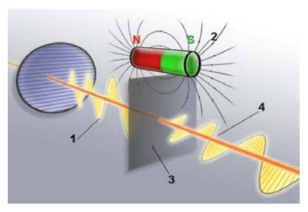
As you can see, the polarization that occurs in the fiberglass material under the influence of a permanent magnet leads to a distortion of the sinusoid, in other words, it forms an angle with the previous sinusoid. On fig. 3 shows the angle formed between the sinusoids.
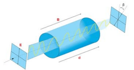
This angle formed between two sinusoids is called the angle of rotation and is denoted β. Then the value of this angle
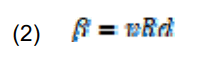
where v – is the velocity of the magnetic field; B-module of the magnetic induction vector; d – is the active length of the optical fiber material.
The measured value of the angle β characterizes the change in the magnetic field.
A change in the magnetic field is instantly perceived by an optical current sensor and transmitted to the “Central Processing Unit”, which is an electronic unit. As a result, the change in the field propagation intensity (E) determines the magnitude and direction of the flowing current [5].
Although the Faraday effect was discovered many years ago, the practical application of this effect in technology falls on the last 15-20 years. Optical current sensors are directly related to the development of digital substations.
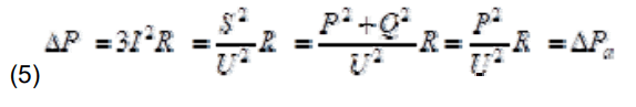
Digital substation means the management of the main and auxiliary equipment located in the substation in an intelligent and digital language. These substations comply with the international standard IEC61850. There are various types of optical current sensor designs, one of which is the ring sensors used in high-voltage busbars of electrical substations, shown in Fig. 4 [6,14,19].

In general, the main advantages of optical current sensors used in electrical substations are:
• Increased resistance to metrological and magnetic influences
• No effects of electromagnetic and ferroresonant phenomena
• Ability for introspection and diagnostics
• Accurate measurement of synchronous harmonics
• Improved dimensions and dimensions
• Simple and safe operation
In the case of the use of optical current sensors in the electrical substations of our country (especially above 110 kV), there will be a significant improvement in the following important indicators of the electrical network:
1. Reducing technical losses in the electrical network
2. Increasing the reliability of power supply (SAIDI, SAIFI).
As you know, technical losses occur in the electrical network for a number of reasons, and reducing these losses has always been considered one of the most important issues. To reduce these losses, the transition to modern technologies, reactive power compensation, power factor improvement, as well as various other methods are used.
If we replace traditional current transformers with optical current sensors in any 220/110/35 kV substation, we will get the following results. We know that technical losses vary with load.
It is clear that it is impossible to reduce technical losses (ΔPa) from active power.
However, losses can be reduced depending on reactive power in various ways, one of which is reactive power compensation. In general, reactive power losses are observed in any equipment with an electromagnetic process in the mains, and each of these losses has an impact on the overall technical losses. Reactive power losses in optical current sensors are not observed [7-9]. More precisely, losses caused by the influence of the electromagnetic field and the saturation of the steel core are not observed in these sensors.
The use of optical current sensors in electrical substations will also significantly increase the reliability of power supply.
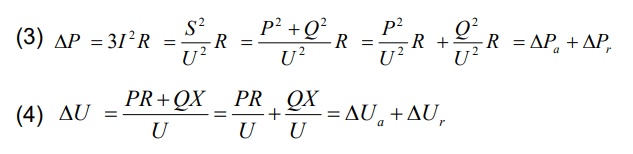
Thus, the ability to accurately measure and store measurement data in memory and accurately analyze will reduce the number of false alarms to zero, which will seriously affect the number of alarms per year (SAIDI) and the duration of alarms per year (SAIFI). The use of optical current sensors in the form of supports in electrical substations is shown in Fig.5 [10, 15].
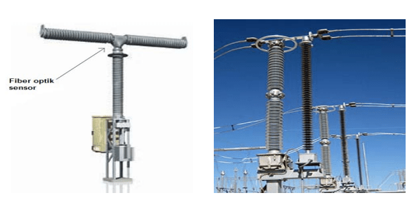
In connection with the transition of electrical substations to digital technology, many companies offer optical sensors current transformers of various shapes and designs. The main types of structures used in substations are shown in the following figure (Fig.6).
Although the types of construction are made in different ways, the principle and essence of optical current sensors do not differ from each other. When designing a substation, the optical current sensor is selected based on the specified power and voltage. Each optical current sensor data sheet will list its main parameters: Due to its ability to conduct accurate analysis, its neutral position in relation to external influences and superior performance, this technology is rapidly spreading around the world. From the point of view of reducing technical losses and increasing the reliability of power supply, the use of this technology in our country is a priority issue.
That is why this technology is expected to be improved and recommended in the near future. In these networks, optical current sensors, which are included in the power supply of only some developed countries, have fully justified themselves. In some countries, equipment based on this technology is still in the testing phase. The creation of smart grids, SCADA, digital substations and other smart grids makes it inevitable that optical technology-based equipment will rapidly develop and become an integral part of the energy supply.
Conclusıon
According to the results of our research, it was determined that the use of optical current sensors based on the Faraday effect in high-voltage electrical substations not only improves the reliability of power supply, but also eliminates some problems that arise in the electrical network. Extraneous effects caused by metrological factors, as well as technical problems caused by magnetic and ferroresonant phenomena, minimizes losses. The use of optical current sensors in electrical substations eliminates the shortcomings of traditional current transformers, which in turn minimizes the inaccuracies and operational failures caused by these shortcomings.
The integration of digital technology into power supply will lead to the creation of new design modifications of optical current sensors, as well as the rapid development of this technology in the energy sector.
REFERENCES
[1] Cease T.W. and Johnston P., “A magneto-optic current transducer”, IEEE Trans. on PowerDelivery, vol. 5, 548-555, 1990.
[2] Bohnert K., Gabus G., Nehring J., and Brändle H., “Temperature and vibration insensitive fiber-optic current sensor”, J. of Lightw.Technol., vol. 20, 267-276, 2002.
[3] Nicatti P.A. and Robert P., “Stabilized current sensor using a Sagnac interferometer”, J. Phys.E: Sci. Instrum., vol. 21, 791-796, 1988.
[4] Torbus S.A., Dutkiewicz P., Projektowanie jednomodowych światłowodów telekomunikacyjnych dla czujników wykorzystujących magnetooptyczne zjawisko Faradaya. Przegląd Elektrotechniczn, Volume 91, No2, pp.118-122, 2015.
[5] Rzayeva S.V., Mammadov N.S. and Ganiyeva N.A. “Overvoltages During Single-Phase Earth Fault in NeutralIsolated Networks (10÷35) kV”. Journal of Energy Research and Reviews 13 (1), pp. 7-13, 2023
[6] Rzayeva S.V., Mammadov N.S., Ganiyeva N.A. “Neutral grounding mode in the 6-35 kv network through an arcing reactor and organization of relay protection against single-phase ground faults”. Deutsche internationale Zeitschrift für zeitgenössische Wissenschaft / German International Journal of Modern Science №42(22) pp.31-34
[7] Enokihara A., Izutsu M., and Sueta T., “Optical fiber sensors using the method of polarizationrotatedreflection”, J. Lightw.Technol., vol. 5, 1584-1590, 1987.
[8] Short S.X., Tselikov A.A., J.U. de Arruda, and Blake J.N., “Imperfect quarter-waveplatecompensation in Sagnac interferometer-typecurrent sensors”, J. Lightw.Technol., vol.16,1212-1219, 1998.
[9] Blake J., Tantaswadi P., and R.T. de Carvalho,“In-line Sagnac interferometer current sensor”,IEEE Trans. Power Delivery, vol. 11, 116-121,1996.
[10] Tang D., Rose A. H., Day G. W., and Etzel S. M., “Annealing of linear birefringence insingle-mode fiber coils: applications to opticalfiber current sensors”, J. Lightw. Technol., vol., 1031-1037, 1991.
[11] Short S.X., Tselikov A.A., J.U. de Arruda, and Blake J.N., “Imperfect quarter waveplatecompensation in Sagnac interferometer-type current sensors”, J. Lightw. Technol., vol. 16,1212-1219, 1998.
[12] Bohnert K. and Nehring J., “Fiber-optic sensing of voltages by line integration of the electricfield”, Opt. Lett., vol. 14, 290-292, 1989.
[13] Gavrichev V. D., Dmitriev A. L., Fiber-optic sensors magnetic field / Study Guide. – St. Petersburg: SPbNIU ITMO, 2013.p. 83
[14] Udd E. Fiber optic sensors. M.: Technosfera, 2008. – 520s.
[15] Jackson R.G. Latest sensors. M: Technosphere, 2007.- 384p.
[16] Horowitz S. H. and Phadke A. G., “Current and voltage ntransformers”, in Power System Relaying, 4th ed. John Wiley and Sons, 2014, ch. 3, pp. 46–73.
[17] Instrument transformers – Part 2: Additional requirements for current transformers, IEC 61869 -2:2012, 2012.
[18] Jackson, D.A. An optical system with potential for remote health monitoring of subsea machinery.Meas. Sci. Technol. 2009, 20, 1–8.
[19] Perciante, C.D.; Ferrari, J.A. Magnetic crosst alk minimization in optical current sensors. IEEETrans. Instrum. Meas. 2008, 57, 2304–2308
[20] Drexler, P.; Fiala, P. Utilization of Faraday mirror in fiber optic current sensors. Radioengineering2008, 17, 101–107.
[21] S.A.Torbus. Current–polarization-dependent loss” optical fibre sensor. Przegląd Elektrotechniczn, Volume 95, pp.171-174, 2015
[22] Zhang P., Halliday D., Faraday Effect Optical Current Sensor, IEEE 0-7803-3143-5 (1996)
Source & Publisher Item Identifier: PRZEGLĄD ELEKTROTECHNICZNY, ISSN 0033-2097, R. 100 NR 2/2024. doi:10.15199/48.2024.02.26
