Published by M.S. ALI1,2, Mahidur R SARKER3, Mohamad Hanif Md SAAD3, Ramizi MOHAMED1, 1Department of Electrical, Electronic and Systems Engineering, Faculty of Engineering and Built Environment, Universiti Kebangsaan Malaysia, Bangi 43600, Malaysia; 2Electrical Engineering Department, German-Malaysian Institute , Jalan Ilmiah, Taman Universiti,43000, Kajang, Selangor, Malaysia; 3Institute of IR 4.0, Universiti Kebangsaan Malaysia, 43600 UKM Bangi, Selangor, Malaysia.
ORCID. 1. 0000-0001-7142-7755, 2. 0000-0002-5363-6219, 3. 0000-0002-1587-964X, 4. 0000-0003-1534-6760
Abstract. Flywheel energy storage system (FESS) technologies play an important role in power quality improvement. The demand for FESS will increase as FESS can provide numerous benefits as an energy storage solution, including a long cycle life, high power density, high round-trip efficiency, and environment friendly. A high-efficiency system is a necessity and a significant element of the overall system in this application. This is because the system determines the size, cost, efficiency, and reliability of the FESS for any application. As a result, choosing an acceptable system topology is a crucial and fundamental part of developing a FESS for portable or residential applications, and it has a big impact on the system’s overall performance. This paper presents an overview of all types of power electronic and controlled system application in FESS, contain numerous topology combinations of DC converters and AC inverters, that are generally employed in FESS for portable or home applications. The switching and controlled system strategies in power conditioning or motor generator synchronisation for FESS are also discussed in this study. Finally, the current problem with FESS is addressed in this study, which comprises a regulated system for system synchronisation with a DC converter and an AC inverter.
Streszczenie. Technologie systemów magazynowania energii w postaci koła zamachowego (FESS) odgrywają ważną rolę w poprawie jakości energii. Zapotrzebowanie na FESS wzrośnie, ponieważ FESS może zapewnić liczne korzyści jako rozwiązanie do przechowywania energii, w tym długi cykl życia, wysoką gęstość mocy, wysoką wydajność w obie strony i przyjazność dla środowiska. W tej aplikacji system o wysokiej sprawności jest koniecznością i istotnym elementem całego systemu. Dzieje się tak, ponieważ system określa rozmiar, koszt, wydajność i niezawodność FESS dla każdego zastosowania. W rezultacie wybór akceptowalnej topologii systemu jest kluczową i fundamentalną częścią opracowywania FESS do zastosowań przenośnych lub domowych i ma duży wpływ na ogólną wydajność systemu. W artykule przedstawiono przegląd wszystkich rodzajów aplikacji energoelektronicznych i systemów sterowanych w FESS, zawierających liczne kombinacje topologii przekształtników DC i falowników AC, które są powszechnie stosowane w FESS do zastosowań przenośnych lub domowych. W niniejszym opracowaniu omówiono również strategie przełączania i sterowania systemowego w kondycjonowaniu mocy lub synchronizacji generatora silnika dla FESS. Na koniec w niniejszym opracowaniu poruszono aktualny problem z FESS, który obejmuje regulowany system synchronizacji systemu z przetwornicą DC i falownikiem AC. (Przegląd topologii systemu sterowania systemu magazynowania energii w postaci koła zamachowego w zastosowaniach energii odnawialnej dla alternatywnych elektrowni)
Keywords: Flywheel energy storage system, DC converter, AC inverter, Control system.
Słowa kluczowe: magazynowanie energii, koło zamachowe, przekształtnik DC
Introduction
In recent years, energy storage systems have become increasingly essential, and the flywheel is one of the oldest storage devices with numerous advantages [1]. Flywheel energy storage systems (FESS) offer environmental and economic advantages in power quality improvement which can be utilized to stability electrical energy supply and demand compared with other energy storage system. Energy storage can be in the form of mechanical, thermal, chemical, or magnetic. FESS stores mechanical energy in a rotating flywheel, which is transformed into electrical energy by a generator and an electrical machine, which drives the flywheel to transfer electrical energy to mechanical energy. Among all types of energy storage system, FESS is the most popular because they can offer many advantages such as a long cycle life, a long operational life, a high round-trip efficiency, a high power density, a low environmental effect, and the ability to store data high level of energy without limitation. In additional of FESS in power system can improve the logistic and dynamic operation of the power quality [2][3][4]. Besides that, FESS can fulfil the requirement of the microgrid operation by providing supplementary services such as frequency and voltage management and smoothing the intermittency of renewable resources [5]. However, the existing system used either in EV or power quality system still facing with many issues and challenges in storing energy. The issues consist of charging/discharging period, protection, consistency, life cycle, size, cost, and power management. FESS become high demand power stability solution because of its ability to store energy during off-peak hours and supply energy during peak hours [6].
There are two types of FESS normally refer to their physical structure and application which is operated in low-speed and high-speed. High speed FESS consists of magnetic bearings, vacuum enclose, and composite disk. Whereby low-speed only usage mechanical bearing and steel flywheel. FESS is an electromechanical energy storage system that comprises of an electrical machine, a back-to-back converter, a DC link capacitor, and a large disc that can interchange electrical power with the electric network. FESS provides an ecologically friendly short or medium-term energy storage system that may be used for a variety of applications in the power system, including power quality enhancement, power smoothing, renewable energy integration support, and system stability enhancement [7].
The study in [8] shows the basic FESS structures commonly used in EVs and power application which is combination between two-machine system or one-machine system with bidirectional power converter. The concept of flywheel energy storage is to store the electrical energy in the form of kinetic energy by rotating a flywheel which is connected mechanically between motor and generator. The electrical power is applied to the motor causing the flywheel spinning high speed, and this spinning mass has kinetic energy is converted back to electrical energy by driven the generator when electrical energy no more applied to the motor [9]. Here, flywheel as a storage of mechanical energy react as a mechanical battery in the system. Normal design of flywheel used in energy storage system is shaped as solid cylinder [2][10]. In [11], the author applied multi criteria decision making approach to choose and validate the material for a flywheel design with appropriate weight selection. This method of optimization is used for nonclassical design algorithm and the result of the design followed the specified set of constraints. There are three main functions of FESS. First, it able to reduce price of electricity. Seconds, it prevents power fluctuation to improve power quality. Third, it helps to achieve the balance between the proper amounts of the generated power with varying demand of load power [12][13].
Due to its limited capability and potency in terms of lifespan, cost, energy and power density, and dynamics response, implementing a hybrid energy storage system that combines two or more energy storage systems is a solution to achieve the desired performance of the power resources and fulfil the desired operation [5]. The flywheels’ strong characteristics make them ideal for limiting the depth of discharge during short-duration discharges and providing fast reaction with a high daily cycle [14]. In [15], the authors analysed a hybrid energy performance using solar (PV) and diesel systems as energy sources, with a flywheel to store excess PV energy. The study looked at the influence of using flywheel energy on power generation, energy costs, and net present cost for a specific hybrid system design. HOMER is a piece of software that allows you to create. Due to its low environmental impact and great efficiency, flywheel energy storage is a nearly mature technology that is being implemented in a variety of sectors and with a variety of innovative systems [16].
Current technology behind the main topology of hybrid flywheel motor generator system Electrical machines
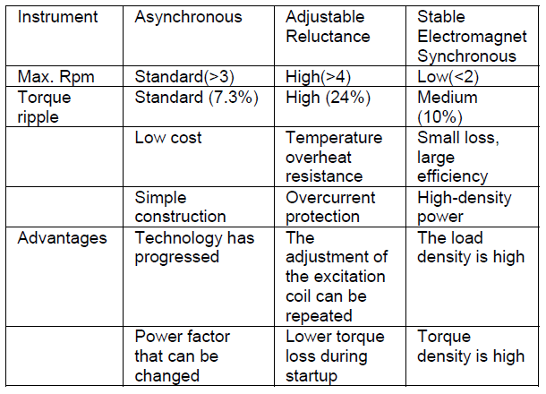
Electrical machinery such as an induction machine, a permanent magnet machine, and a variable reluctant machine are commonly employed in FESS. An induction motor such a squirrel cage type is used due to low cost, its ruggedness, higher torque and can be used for high power application. On the other side, the variable reluctant machine offered a wide speed range with simple control mechanism with low idling losses and very robust, but it has low power density and power factor with high torque ripple. The permanent magnet machine, on the other hand, has a high power efficiency, high power density, and low rotor losses, but it is expensive, has low tensile strength, and has idling losses due to stator eddy current losses [17]. Table 1 shows that the comparison of electrical machine proper utilize in FESS [18][2].
Table 1. The comparison of electrical machine proper utilize in FESS.
In [19], the authors investigated the nonlinear dynamics of a turbine generator with a squeeze film damper under the action of rub-impact in the oil film rupture. When the rotor speed ratio is minimal, the system performs period-one motion, but the periodic motion abruptly transforms into aperiodic motion with no transition. The squeeze film damper, on the other hand, fails to support the rotor within a given speed range.
In [20], the authors indicated the performance and control strategy of synchronous and induction machines that are employed in FESS. The performance of FESS is heavily dependent on the type of motor/generator (MG) combination, which is the primary component for generating or absorbing power from the grid and is made up of three categories of electrical machines: synchronous, induction, and switching reluctant machines. Induction machines are typically utilized for high-power applications, synchronous machines are used for high-speed applications, and switched reluctant machines are used less frequently because to large current ripples.
Magnetic FESS development
The study in [21] designed an unique flywheel energy storage device that relied on hybrid mechanical-magnetic bearings for assistance. The suggested design uses active magnetic bearings and an axial flux permanent magnet synchronous machine to allow the rotor-flywheel to spin while remaining in magnetic levitation in a vertical configuration. The axial-flux permanent magnet motor has a rotor and stator, with the rotor positioned between two disc-type stators and able to move along the sliding bar. However, its movement is limited to half of the air-gap length, with a 0.5mm departure from the middle point between the two stators. From experimental result show that the flywheel velocity increase from 0 to the rated speed in the charging stage and keep constant in energy maintenance stage to store energy. The speed decrease 10% in discharge stage to release energy. As a result, the proposed conceptual FESS with a compact flywheel energy storage system supported by an axial flux partially self-bearing permanent magnet machine has been proven as possible in experimental implementation.
In [22], the authors demonstrated that a fully integrated flywheel energy storage system with a high-temperature superconducting magnet suspension allows for stable flywheel levitation. The thrust bearing forces are regulated by permanent magnets, and the initial centre of the flywheel is located in a vacuum chamber, which improves system efficiency and reduces losses. To meet the need of spacecraft altitude control accuracy, the authors presented an instantaneous torque control of a magnetically hung reaction flywheel in [23]. To increase the torque-output precision of the magnetically hung reaction flywheel, a new torque control approach is proposed. To minimise diode freewheeling of the inactive phase in the conduction zone and modulate the switching-in phase during the high-speed region, a novel PWM pattern is used. To eliminate microscopic vibration, Qiang et al. [24] built a novel repeatable launch locking/unlocking device for a magnetically suspended momentum flywheel. In [25], the authors suggested an active vibration control unit with a flywheel inertial actuator for reducing distributed structural flexural vibration. To operate this actuator, the moving components of the actuator work together with a traditional coil-magnet transducer and flywheel element to generate the rotating inertia effect. This proposed actuator able to implement feedback control units which robust to shock, improve stability and vibration control effects.
In [26], the authors analysed a superconducting levitation of the flywheel system based on the H-formulation to provide a guideline for electromagnetic behaviours in the flywheel system design. Levitation forces are created by independent interactions between axial and radial bearings. The proposed design, which uses a single ring-shaped superconductor and more permanent magnets, will provide a higher stiffness characteristic. This concept comprised the multi-surface levitation by instrumentation up to 125.6% axial force and provided high force density in improvement of the flywheel system. In [27], the authors designed a stabilised flywheel unit for efficient energy storage by developing a unit with revolving flywheel for storing energy and therefore decreasing the supply-demand gap. This design aims to extract the least amount of energy from the flywheel while maintaining all five degrees of freedom.
Energy storage flywheel supported with active magnetic bearing become popular in academic or industry due to their offer many advantages such as short charging time, high specific energy, long life span and no pollution. The study in [28] constructed a rotor-AMB test rig to emulate the operation of such flywheel. In [29], the author developed REBCO high temperature superconducting magnet bearing for large capacity FESS which consist of a high temperature superconducting bulk and double-pancake coils used second generation REBCO wires. The study in [30] developed of superconducting magnetic bearing for FESS that consist of high temperature superconducting coil and bulks. This proposed design has capability of 300kW and storage capability of 100kWh by implement high inertia flywheel with diameter 2m and 4000kg weight. In [31], the authors designed an active magnetic bearing system with off-board power supply system to keep the suspension stable of the flywheel rotor at the equilibrium point. The onboard power supply cannot operate when equilibrium point cause the magnetically suspended FESS suffers fatal damage. The dynamic displacement of the flywheel rotor at equilibrium status always occurs when the dynamic braking of flywheel rotor is realized by discharge of the magnetically suspended FESS. The results show that by discharging magnetically suspended FESS and increasing the energy storage of magnetically suspended FESS with constant flywheel rotor speed, the off-board power source can maintain the mechanism of an active magnetic bearing. This mechanism also can avoid collision between unstable rotors at high rotation speed with stator.
Hybrid topologies
Sebastian et al. proposed a model of low-cost low-speed FESS (LS-FESS) to increase the power quality of the hybrid diesel and wind generator for isolated micro grid. An asynchronous machine used to drive a steel flywheel as LSFESS to provide low cost and simple maintenance which is important for remote location of the wind diesel power system. An asynchronous machine is chosen because its offer cheaper, high torque, suitable for many application, and robust. The power quality improvement proposed in this micro grid shown as a simulation model. In [32], the authors designed control strategy to manage between FESS and wind turbines by using frequency control to maintain the level of power reserves adjusted by network operator according to the wind turbines operation. This work focusing to design control strategy for wind turbine to fulfil the requirement of power reserves and to manage the system between this hybrid power sources by regulating the frequency controller. This controlling method by adjusting rating of variable-speed wind turbine make improvement of power margin of all wind speed range either below or above rated of wind speed. This frequency control can provide kinetic energy due to the variation of rotation speed of turbine exchanged with the network. Application of the flywheel in this system can reduce the need of wind turbine power generation by reloading extra power to the network.
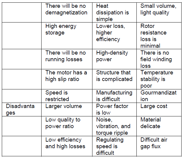
The study in [33], presented a power converting system hybrid energy storage and wind turbine by introducing two techniques of directions which are torque control and power control. This system links each other between flywheel, induction machine and power converters to the wind power generator via provided DC network. These direct controls which give faster response by eliminate the loop of variable regulation controlled and block of pulse width modulation. The implementation of this direct torque controlled to the double fed induction generator hybrid with FESS will increase the accuracy of the system. Fig 1 shows the overall system under study that proposed by the authors [33].
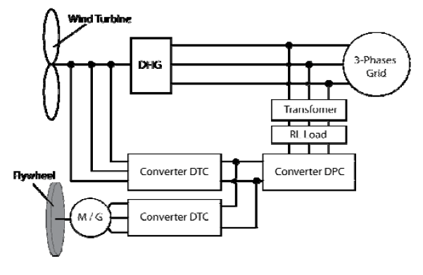
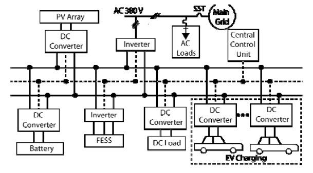
In [34], the authors applied flywheel to support the hybrid system of renewable energy with power management system. This power management system presents a control technique to manage the hybrid system between FESS and stand-alone wind-diesel generator. In this topology, application of FESS make improvement to the dynamic performance of the overall system in various situations such as load increasing, low operation of wind turbine and diesel engine. In this system, flywheel and induction motor controlled by machine power controller which is FES will deliver to the load during low power generated by other power sources. In [35], the study proposed a flywheel hybridization in energy storage system in renewable energy sources to improve battery life. This work purposely to verified the advantages of hybrid energy storage system between solar and FESS used for residential micro-grid. It is proved that the flywheel applied in the system make large improvement of the battery duration almost triple. Fig 2 shows the micro-grid layout for this proposed system, which is consists of solar panel, PV converter, battery converter, battery, flywheel converter, FESS, bidirectional inverter, user load and grid [35].
In [36], the authors presented a study of hybrid flywheel with reversible Solid Oxide Cell in micro-grid to improve capabilities of the peak-shaving and fast-ramping in power quality for renewable power sources. The limitation of the reversible Solid Oxide Cell which poor load-following capability that required hybridization to provide regulation in short time interval. This power management topology introduces two types of storages which are short-term and long-term storage to handle the power peaks and to extend storage capacity. The investigation shows that this hybridization make improvement in increasing of self-consumption efficiency up to 58.04%. Fig 3 shows the overall system architecture, which included of solar panel, PV converter, battery converter, reversible Solid Oxide Cell, Hydrogen storage, flywheel converter, FESS, bidirectional inverter, load, and grid [36].

The testing circuit diagram as shown in Fig 3 is used to analysis the system. From this testing circuit, the effect of the flywheel with different sizes and weights can be analyzed [37]. From this testing circuit also, the synchronization of the motor and generator can be measure. All the data measurements of the motor and generator such as stator current, torque, speed, input, and output voltage are being measured as shown in this figure. All measurements consist of a multi-meter to display the root mean square (RMS) value and the scope to plot the graph. The voltage supply also can be set according to the motor specification by changing the parameter of the supply relay three-phase.
Application of FESS
In [38], the authors applied flywheel energy storage to maintain current and efficiency in the modern resistance spot welding system. This system approach gives better result with high efficiency more than 80% compare with capacitor storage system. The motor-generator combination in this system purposely to boost the voltage and reduce electrical frequency. Fig 4 shows the proposed system topology that consist of 3-phases inverter, motor, generator, flywheel, and welding power supply [38].

The study in [39] designed geared transmission for hybrid vehicles to optimise the flywheel energy storage by coupling a FESS to the gear system which can recover the energy when braking and boost more energy for acceleration. Rupp et al. [36] analysed a FESS for light rail transit train to reduce operating cost by reducing energy used in the system. The result of the analysis show that cost saving up to 11% can be obtained with 1.2kWh and 360kW. In [40], the suthors resolved the limitation of the fuel cell by integrating the magnetic flywheel as a hybrid system control. This system hired two type of control method which known as particle swarm optimization and multiple adaptive neuro-fuzzy interface [41]. Fig 5 shows the magnetic flywheel system architecture proposed by the author [40]. In [42], the authors developed Kinetic Driven Flywheel by coupling the flywheel to the crankshaft to reduce mechanical vibration in this part. A new design of gearbox with double-crank which can adjustable the length and cycloidal shape. In [43], the authors found the optimize number and the best capability of the flywheel rotor that can be used to minimize the used of power in light metro trains by introducing a new design of multi-ring flywheel rotor. The result shows that this design can be handled about 1620- 3420kW of the power needed in the system.
In [44], the authors studied how to reduce load fluctuations in ship electrical system by adding hybrid energy storages between battery and flywheel. In the ship development either for commercial or military recently are focusing on ship electrification but there are challenges for electric-ship propulsion system which facing with large propulsion-load fluctuations. The power sources from the battery and flywheel become a buffer to separate load fluctuations from the all-electric ship system.
In [45], the authors studied how to maintain the rate of energy stored in the form of moment inertia and angular frequency connected directly the grid. This approach not required power electronic as interface and capable to connect directly to grid. A prototype developed in this study able to generate high power for charging and discharging ability in several second in one period. However, the efficiency of this system controller need improvement to obtain a feasible fixed-speed FESS in regulating moment of inertia.
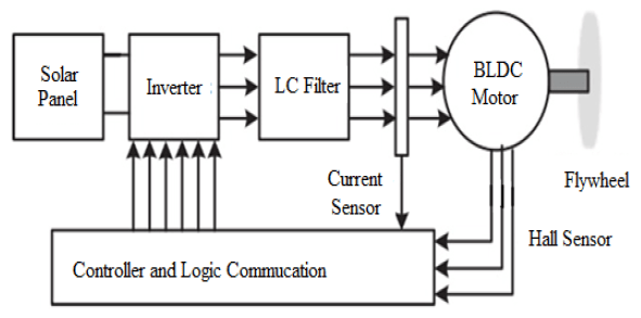
A satellite power system required solar panel to provide energy and orientation but in the dark region in orbital path required FESS. The study in [46] implemented a FESS for the space application. Fig 6 shows the current reference method (CRM) and FESS in the proposed system that consist of solar pane, inverter to converter DC to AC 3- phases, LC filter to stabilize the voltage, brushless DC motor and flywheel [46]. In [47], the authors designed a model of flywheel micro vibration isolation system to isolate the micro vibrations generated by high speed operating flywheel induce to unstable spacecraft payload and network bus. In [48], the authors studied about the effect of supercapacitors to the satellite power system by using torque flywheel whereby the traditional satellite power system has limitation on the battery capacity and space to meet the requirement of the high torque flywheel. The study in [49] tested the flywheel micro vibration with six component test benches to study the impact of flywheel micro vibration that produce high-resolution optical satellite with space-borne integrated. This impact of this vibration can be resolve by applying flywheel vibration isolator on the camera. The study in [50] designed vibration reduction for the flywheel system to study about nonlinear energy sink. This system should be able to meet requirement of structural strength, amplification of resonance peak and other performance needed in aerospace engineering. In [51], studied about the advancement flywheel motor powered by human has been applied at rural area. The investigation on the various research proved that the flywheel motor powered by human can produce until 5hp that can be utilized in rural area for different types of motorized machines application.
Limitations of FESS
Flywheel can be dangerous element in machine system, caused catastrophic and explosion when any failure happened to their body structure due to the stored kinetic energy can be released in the fast respond. Any failure occurs in the FESS required high level of expertise when the traditional approach by using human engineered features applied to detect a fault. In [52], the authors proposed a solution to detect fault in the FESS by using vibration-based fault detection method to monitor the flywheel condition. This experiment proved that the vibration signal can be detected by using data-driven method to observe faulty operation at the end of flywheel life with high accuracy.
Induction machines (IM), permanent magnet machines (PM), and variable reluctance machines (VRM) are common electrical machinery used in FESS [53][54]. Because of its ruggedness, increased torque, and low cost, an IM is employed in high-power applications [55]. The main issues with IMs are speed restrictions, difficult control, and increased maintenance requirements [56]. Because of its better efficiency, high power density, and reduced rotor losses, the PM is the most widely utilised machine for FESS [57]. Due to the speed restrictions of IMs and the torque ripple, vibration, and noise of VRMs, it is commonly utilised in high-speed applications. The issue with a PM is its high price, limited tensile strength, and idling losses due to stator eddy current losses [17]. Hybrid PM reluctance machines have been developed to alleviate these drawbacks.
Recent development in FESS
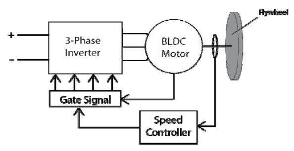
In study in [58] presented a new digital technique of pulse width modulation (PWM) to control six pulse three-phase inverter for brushless direct current (BLDC) motor drive controlled by using Spartan 3AN field programmable gate array (FPGA). The advantage of this control technique is low cost and able for high speed performance. Fig 7 shows the system topology of the control technique proposed by the author [58].
The study in [59] presented a novel of Input-Output Linearization AC voltage controlled for Dynamics Voltage Restores with proportional integral (PI) controller. The flywheel in the shape of cylinder with vertical axis from seamless steel hollow is driven by AC-AC matrix converter presented higher response speeds [60][61].
In [62], the authors designed an integrated system between flywheel and triboelectric nanogenerator with spiral spring to store energy in the form of a continues rotational energy of a flywheel and the potential energy of a spiral spring that can improve energy harvesting of intermittent excitations. In [63], the study proposed a magnet coil power supply for a small tokamak by using a self-excited induction generator couple with flywheel which is tokamak devices required large amount of pulse power consumption when the power grid is not robust enough. This proposes system succeed to achieve a peak power at 117kW and 55kW rated induction motor/generator in 0.25s flattop period. Fig 8 shows the main topology of the proposed system of self-excited induction generator [63].
In [64], the authors designed FESS to improve quality of electrical energy by using three-phase induction machine to drive high inertial loads of flywheel applied to synchronized grid generator system. This proposed system shows how to connect a high inertial cylindrical flywheel to the induction machine to improve stability in the grid. The result of this experiment shows that application of the cylindrical flywheel into the grid make improvement in power quality by increasing energy conservation efficiency.

In [65], the authors solved the limitation of the wind power due to the intermittent nature of power generation depending to the weather by adding flywheel energy storage technology to the system. This application of FES in the system can improve the power stability supply to the load at constant value. However, the output power to grid still unstable when FESS reaches at its limit and the power of wind turbine fluctuate.
The study in [66] proposed a control system that consist of fuzzy controller to create regulating speed of wind generator that used permanent magnetic synchronous generator and coupling to the FESS. The FESS in this proposed system purposely used to vary the power supply connected to DC bus stage. The extra power stored in the FESS and will use when needed. The FESS in this system consists of squirrel-cage induction motor and flywheel.
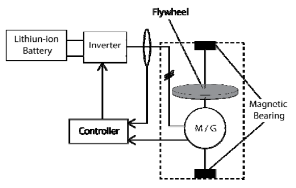
In [67], the authors used synchronous reluctance motor supported with permanent magnet in the FESS with vector digital controller which consist of offset and dead zone measurement error ability. This control system able to handle unstable speed of the motor. In [68] make improvement to the power frequency stability with hierarchical control for DC micro-grid in Electrical vehicle (EV) charging station with hybrid power source between FESS, solar and battery. Fig 9 shows the micro-grid topology EV charging station with hybrid power source proposed by the author [68].
The study in [69] applied flywheel to the robot motion by supporting two point rough plane with regulating internal friction and mass. This proposed design of flywheel with an eccentric mass and control algorithm is purposely to solve the problem of the planar motion caused by friction in the robot mechanism.
Issues and Challenges
The first issue is to increase the duration of electrical power generation from the existing flywheel energy storage system by increasing the efficiency of the system [70][71]. Due to bearing friction and air resistance causes the flywheel to stop rotating. In order to increase the generation period to occur without interruption then the energy loss caused by friction and air resistance must be reduced or eliminated. With a view to obtaining a longer period of electricity generation while improving the efficiency of existing systems, various efforts have been undertaken. Typically, magnetic bearings and vacuum housings have been used to solve this problem. Normally, steel flywheels commonly used in energy storage systems are dependent on mechanical energy caused by inertia [72]. The presence of friction and air resistance on the mechanical system causes the mechanical energy stored in the flywheel to be reduced and depleted.
The second issue is to overcome the problem of starting the rotation of the flywheel at the beginning of operation which requires high torque as well as low power consumption to improve the efficiency of the system [73]. For systems that are on the grid, high-powered motors can be used without any problems. The disadvantage of using a high-powered motor is that it will result in high power consumption and maintenance costs. After the system has already achieved synchronous speed at the set point, the torque required to maintain the speed already low then only needs a low-power motor for this purpose. For conventional systems, the operator will use a manual method to assist the motor to rotate the generator and flywheel at the start of operation [74]. This method is not suitable for automated systems used for emergency operations or backup power supplies. High torque is required for starting of operation to gain resistance forces resulting from the weight of the flywheel, bearing friction, and air resistance. For off-grid systems applications, the use of high-powered motors becomes a challenge that needs to be overcome. The energy produced from solar, or wind energy is noncontinuous energy. So, a motor that uses low power is more suitable to be used to drive the flywheel at the start of operation. Typically, electrical power generated from solar, or wind energy is direct current [75]. Direct current energy will be stored in the battery for further use. Here a single-phase inverter will be used to convert direct current to alternating current. The use of high-powered motors also will increase the cost of system development and maintenance.
This flywheel energy storage system also requires motor speed control at the nominal speed level required by the generator to produce the optimal output voltage [76][77]. A high-efficiency control system is required to ensure that the motor can drive the generator at the required speed. However, the speed of a motor that is changed by using a frequency inverter requires a control system that can keep the system moving at the desired speed constantly. The motor speed cannot be automatically determined to be at the desired speed level if no closed-loop control system is applied in the system.
Non-stop electrical power generation is becoming a new challenge in the world of flywheel power generation system technology research [63][78]. Ongoing research has been conducted so that a non-stop continuous energy generation system becomes a reality. The importance of producing something new for this study provides a new idea and discovery that benefits the industry and even the world of research. To date, an electric power generation system with a non-stop continuous flywheel energy storage system is still unrealistic, but it has not become impossible to find.
Studies are still ongoing to achieve this dream and this system is also known as a free energy generator [79].
Conclusions and Recommendations
The FESS with various topologies gives many benefits in renewable energy application for alternative power plant, especially for micro-grid. A review on FESS application shows that they can be used in various field of technology from vehicle until to space. Application of FESS with automated system and power electronic make the power plant or micro-grid produce more efficient energy conversion of the power from renewable energy to the load. Using of FESS equipped with converters and inverters can address the limitation of Flywheel system drive, which include high starting torque, low voltage supply, unregulated voltage, and unstable power. A hybrid flywheel with solar panel, wind turbine or battery or other source can stabilize the power conditioning to balance and fulfil the excess and insufficient power condition in the micro-grid. This review also shows that the development of magnetic technology with various technique use for FESS improvement. Application of permanent magnet motor, hybrid mechanical and magnetic bearing in FESS introduces improvements in terms of increased efficiency of the system. The topology of the hybrid micro-grid technology can be divided into three stage which are renewable energy power source such solar or wind generator, storage energy system such battery charging system or flywheel storage system, and power electronic such a converter or inverter to control the power to the load.
In conclusion, the design of control systems and power electronic topologies is considered important in FESS to increase the reliability of the system can be used anywhere and anytime. Therefore, more research on the development of new topologies for FESS with new switching technique control for power electronic or improve the existing technology in the flywheel system drive to create a more robust application. Currently, there are many improvements focused on mechanical friction and air resistance due to the power loss in the system but not in control and power electronics. FESS with improved power electronic technologies and intelligent control systems can be considered as promising alternative energy storage for the micro-grid application.
• For future recommendations, the approach taken are with the addition of hybrid flywheels to the flywheel energy storage system has been made. With the addition of hybrid flywheels consisting of steel flywheels and magnetic flywheels, this storage system no longer relies on inertia alone. With these improvements, the friction and resistance that reduce the energy stored in the flywheel can be overcome. Therefore, the duration of electric power generation will increase, and the efficiency of the system will be higher.
• Here, the frequency inverter is the best choice to control the speed of the squirrel cage motor. This is because the frequency inverter controls the motor speed by simply changing the frequency of the three-phase power supply resulting from the three-phase full-bridge inverter method with six IGBT as the switch without using the resistance control method which will cause high power loss and energy waste.
• Pulse width modulation used to control the frequency of the inverter does not cause power loss when a power change occurs. In addition, a frequency inverter can be used only connecting to a single-phase power supply to run a three-phase motor. This is because a frequency inverter will produce a three-phase power supply as its output voltage. Just by changing the frequency of the inverter. The motor speed will change without changing the supply voltage. By increasing the frequency of the inverter, the motor will rotate faster.
• The star and delta connection method with a combination of low-power motors can provide improvements to the system by providing sufficient torque for the high-inertia flywheel drive motor at the start of operation. This hybrid method of double star and delta connection can produce high torque and driving force at highly efficient speeds. The double delta connection can be used to drive the flywheel at the beginning of the operation and after reaching the desired speed synchronously with the motor, flywheel, and generator are at the same speed, and then the system can change the double star connection to continue operation. The use of a lower current will increase the efficiency of the system and reduce power consumption.
Acknowledgment – Universiti Kebangsaan Malaysia for funding the research under Grant Code GGPM-2021-050.
REFERENCES
1. Mousavi G, S.M.; Faraji, F.; Majazi, A.; Al-Haddad, K. A comprehensive review of Flywheel Energy Storage System technology. Renew. Sustain. Energy Rev. 2017, 67, 477–490, doi:10.1016/J.RSER.2016.09.060.
2. Amiryar, M.E.; Pullen, K.R. A Review of Flywheel Energy Storage System Technologies and Their Applications. Appl. Sci. 2017, Vol. 7, Page 286 2017, 7, 286, doi:10.3390/APP7030286.
3. Sebastián, R.; Peña-Alzola, R. Control and simulation of a flywheel energy storage for a wind diesel power system. Int. J. Electr. Power Energy Syst. 2015, 64, 1049–1056, doi:10.1016/J.IJEPES.2014.08.017.
4. Sarker, M.R.; Mohamed, A.; Mohamed, R. Performance evaluation modeling a Microelectromechanical system based Finite Element piezoelectric shear actuated beam. Prz. Elektrotechniczny 2015, 91.
5. Hajiaghasi, S.; Salemnia, A.; Hamzeh, M. Hybrid energy storage system for microgrids applications: A review. J. Energy Storage 2019, 21, 543–570, doi:10.1016/J.EST.2018.12.017.
6. Faisal, M.; Hannan, M.A.; Ker, P.J.; Hussain, A.; Mansor, M. Bin; Blaabjerg, F. Review of energy storage system technologies in microgrid applications: Issues and challenges. IEEE Access 2018, 6, 35143–35164, doi:10.1109/ACCESS.2018.2841407.
7. Arani, A.A.K.; Karami, H.; Gharehpetian, G.B.; Hejazi, M.S.A. Review of Flywheel Energy Storage Systems structures and applications in power systems and microgrids. Renew. Sustain. Energy Rev. 2017, 69, 9–18, doi:10.1016/J.RSER.2016.11.166.
8. Hannan, M.A.; Hoque, M.M.; Mohamed, A.; Ayob, A. Review of energy storage systems for electric vehicle applications: Issues and challenges. Renew. Sustain. Energy Rev. 2017, 69, 771–789.
9. ALI, M.S.; SARKER, M.R.; IBRAHIM, A.A.; MOHAMED, R. A High Gain Variable Boost DC-DC Converter for Low-Voltage Hybrid Direct Methanol Fuel Cell Batteries. Prz. Elektrotechniczny 2021, 97, 1–10, doi:10.15199/48.2021.11.01.
10. Sarker, M.R.; Mohamed, R. A Batteryless low input voltage micro-scale thermoelectric based energy harvesting interface circuit with 100mV start-up voltage. Prz. Elektrotechniczny 2014, 90.
11. Okokpujie, I.P.; Okonkwo, U.C.; Bolu, C.A.; Ohunakin, O.S.; Agboola, M.G.; Atayero, A.A. Implementation of multi-criteria decision method for selection of suitable material for development of horizontal wind turbine blade for sustainable energy generation. Heliyon 2020, 6, e03142, doi:10.1016/J.HELIYON.2019.E03142.
12. Wu, Y.; Bingham, C.M.; Peel, D.J.; Howe, D. Active magnetic bearings for a flywheel peak power buffer for electric vehicles. Int. J. Appl. Electromagn. Mech. 2001, 15, 201–206.
13. Jin, Z.; Sun, X.; Yang, Z.; Wang, S.; Chen, L.; Li, K. A novel four degree-of-freedoms bearingless permanent magnet machine using modified cross feedback control scheme for flywheel energy storage systems. Int. J. Appl. Electromagn. Mech. 2019, 60, 379–392.
14. Pullen, K.R. The Status and Future of Flywheel Energy Storage. Joule 2019, 3, 1394–1399, doi:10.1016/J.JOULE.2019.04.006.
15. Ramli, M.A.M.; Hiendro, A.; Twaha, S. Economic analysis of PV/diesel hybrid system with flywheel energy storage. Renew. Energy 2015, 78, 398–405, doi:10.1016/J.RENENE.2015.01.026.
16. Wicki, S.; Hansen, E.G. Clean energy storage technology in the making: An innovation systems perspective on flywheel energy storage. J. Clean. Prod. 2017, 162, 1118–1134, doi:10.1016/J.JCLEPRO.2017.05.132.
17. Hedlund, M.; Abrahamsson, J.; Pérez-Loya, J.J.; Lundin, J.; Bernhoff, H. Eddy currents in a passive magnetic axial thrust bearing for a flywheel energy storage system. Int. J. Appl. Electromagn. Mech. 2017, 54, 389–404.
18. Sarker, M.R.; Mohamed, R.; Saad, M.H.M.; Tahir, M.; Hussain, A. Vibration based energy harvesting system for mobile device charging. Int. J. Appl. Electromagn. Mech. 2020, 65, 149–169.
19. Hsu, W.-C.; Wang, C.-R.; Shiau, T.-N.; Liu, D.-S.; Young, T.-H. Nonlinear Dynamic Study on Effects of Flywheel Eccentricity in a Turbine Generator with a Squeeze Film Damper. Procedia Eng. 2014, Complete, 397–406, doi:10.1016/J.PROENG.2014.06.360.
20. Soomro, A.; Amiryar, M.E.; Pullen, K.R.; Nankoo, D. Comparison of Performance and Controlling Schemes of Synchronous and Induction Machines Used in Flywheel Energy Storage Systems. Energy Procedia 2018, 151, 100–110.
21. Zhang, C.; Tseng, K.J. Design and control of a novel flywheel energy storage system assisted by hybrid mechanical-magnetic bearings. Mechatronics 2013, 23, 297–309, doi:10.1016/J.MECHATRONICS.2013.01.008.
22. Dergachev, P.; Kosterin, A.; Kurbatova, E.; Kurbatov, P. Flywheel energy storage system with magnetic hts suspension and embedded in the flywheel motor-generator. In Proceedings of the Proceedings – 2016 IEEE International Power Electronics and Motion Control Conference, PEMC 2016; Institute of Electrical and Electronics Engineers Inc., 2016; pp. 574–579.
23. Jian, F.; Kun, L.; Jingbo, W. Instantaneous Torque Control of Magnetically Suspended Reaction Flywheel. Energy Procedia 2016, 100, 297–306, doi:10.1016/J.EGYPRO.2016.10.181.
24. Qiang, L.; Kun, W.; Yuan, R.; Peilan, P.; Limei, M.; Zhaojing, Y. Novel repeatable launch locking/unlocking device for magnetically suspended momentum flywheel. Mechatronics 2018, 54, 16–25, doi:10.1016/J.MECHATRONICS.2018.07.002.
25. Kras, A.; Gardonio, P. Active vibration control unit with a flywheel inertial actuator. J. Sound Vib. 2020, 464, 114987, doi:10.1016/J.JSV.2019.114987.
26. Quéval, L.; Liu, K.; Yang, W.; Zermeño, V.M.R.; Ma, G. Superconducting magnetic bearings simulation using an Hformulation finite element model. Supercond. Sci. Technol. 2018, 31, 084001, doi:10.1088/1361-6668/AAC55D.
27. Šonský, J.; Tesař, V. Design of a stabilised flywheel unit for efficient energy storage. J. Energy Storage 2019, 24, 100765, doi:10.1016/J.EST.2019.100765.
28. Lyu, X.; Di, L.; Yoon, S.Y.; Lin, Z.; Hu, Y. A platform for analysis and control design: Emulation of energy storage flywheels on a rotor-AMB test rig. Mechatronics 2016, 33, 146– 160, doi:10.1016/J.MECHATRONICS.2015.12.007.
29. Mukoyama, S.; Matsuoka, T.; Furukawa, M.; Nakao, K.; Nagashima, K.; Ogata, M.; Yamashita, T.; Hasegawa, H.; Yoshizawa, K.; Arai, Y.; et al. Development of REBCO HTS Magnet of Magnetic Bearing for Large Capacity Flywheel Energy Storage System. Phys. Procedia 2015, 65, 253–256, doi:10.1016/J.PHPRO.2015.05.139.
30. Miyazaki, Y.; Mizuno, K.; Yamashita, T.; Ogata, M.; Hasegawa, H.; Nagashima, K.; Mukoyama, S.; Matsuoka, T.; Nakao, K.; Horiuch, S.; et al. Development of superconducting magnetic bearing for flywheel energy storage system. Cryogenics (Guildf). 2016, 80, 234–237, doi:10.1016/J.CRYOGENICS.2016.05.011.
31. Xiang, B.; Wong, W. Power compensation mechanism for AMB system in magnetically suspended flywheel energy storage system. Measurement 2021, 173, 108646, doi:10.1016/J.MEASUREMENT.2020.108646.
32. Díaz-González, F.; Hau, M.; Sumper, A.; Gomis-Bellmunt, O. Coordinated operation of wind turbines and flywheel storage for primary frequency control support. Int. J. Electr. Power Energy Syst. 2015, 68, 313–326, doi:10.1016/J.IJEPES.2014.12.062.
33. Hamzaoui, I.; Bouchafaa, F.; Talha, A. Advanced control for wind energy conversion systems with flywheel storage dedicated to improving the quality of energy. Int. J. Hydrogen Energy 2016, 41, 20832–20846, doi:10.1016/J.IJHYDENE.2016.06.249.
34. Pathomchaiwat, P.; Neammanee, B. Control of power management in the renewable energy system by using Flywheel Energy Storage. ECTI-CON 2017 – 2017 14th Int. Conf. Electr. Eng. Comput. Telecommun. Inf. Technol. 2017, 513–516, doi:10.1109/ECTICON.2017.8096287.
35. Barelli, L.; Bidini, G.; Bonucci, F.; Castellini, L.; Fratini, A.; Gallorini, F.; Zuccari, A. Flywheel hybridization to improve battery life in energy storage systems coupled to RES plants. Energy 2019, 173, 937–950, doi:10.1016/J.ENERGY.2019.02.143.
36. Baldinelli, A.; Barelli, L.; Bidini, G. Progress in renewable power exploitation: reversible solid oxide cells-flywheel hybrid storage systems to enhance flexibility in micro-grids management. J. Energy Storage 2019, 23, 202–219, doi:10.1016/J.EST.2019.03.018.
37. Caruso, J.F.; Coday, M.A.; Davidson, M.E.; Riner, R.D.; Borgsmiller, J.A.; Olson, N.M.; Taylor, S.T.; McLagan, J.R. The effect of flywheel-based resistive exercise workouts on testosterone/cortisol ratios. Isokinet. Exerc. Sci. 2012, 20, 51–60.
38. Hagemeyer, M.; Frohleke, N.; Krishna, D.V.M.M.; Bocker, J. Development of a flywheel energy storage-based welding system. 2016 IEEE 2nd Annu. South. Power Electron. Conf. SPEC 2016 2016, doi:10.1109/SPEC.2016.7846049.
39. Read, M.G.; Smith, R.A.; Pullen, K.R. Optimisation of flywheel energy storage systems with geared transmission for hybrid vehicles. Mech. Mach. Theory 2015, 87, 191–209, doi:10.1016/J.MECHMACHTHEORY.2014.11.001.
40. Huang, C.N.; Chen, Y.S. Design of magnetic flywheel control for performance improvement of fuel cells used in vehicles. Energy 2017, 118, 840–852, doi:10.1016/J.ENERGY.2016.10.112.
41. Ali, M.S.; Sarker, M.R.; Ibrahim, A.A.; Mohamed, R. High efficiency flywheel motor generator model with frequency converter controlled. Prz. Elektrotechniczny 2021, 97, 184–189, doi:10.15199/48.2021.11.34.
42. Pfabe, M.; Woernle, C. Reducing torsional vibrations by means of a kinematically driven flywheel — Theory and experiment. Mech. Mach. Theory 2016, 102, 217–228, doi:10.1016/J.MECHMACHTHEORY.2016.03.011.
43. Rastegarzadeh, S.; Mahzoon, M.; Mohammadi, H. A novel modular designing for multi-ring flywheel rotor to optimize energy consumption in light metro trains. Energy 2020, 206, doi:10.1016/J.ENERGY.2020.118092.
44. Hou, J.; Sun, J.; Hofmann, H. Control development and performance evaluation for battery/flywheel hybrid energy storage solutions to mitigate load fluctuations in all-electric ship propulsion systems. Appl. Energy 2018, 212, 919–930, doi:10.1016/J.APENERGY.2017.12.098.
45. Kondoh, J.; Funamoto, T.; Nakanishi, T.; Arai, R. Energy characteristics of a fixed-speed flywheel energy storage system with direct grid-connection. Energy 2018, 165, 701–708.
46. Çelikel, R.; Özdemir, M.; Aydoǧmuş, Ö. Implementation of a flywheel energy storage system for space applications. Turkish J. Electr. Eng. Comput. Sci. 2017, 25, 1197–1210.
47. Wei, Z.; Li, D.; Luo, Q.; Jiang, J. Modeling and analysis of a flywheel microvibration isolation system for spacecrafts. Adv. Sp. Res. 2015, 55, 761–777, doi:10.1016/J.ASR.2014.10.036.
48. Wu, Q.; Zhu, M.; Li, F.; Chi, X.; Lin, W.; Luo, Y.; Ma, L. Effect of Supercapacitors Supply on the High Torque Flywheel for Satellite Power System. IFAC-PapersOnLine 2017, 50, 9419– 9425, doi:10.1016/J.IFACOL.2017.08.1458.
49. Li, L.; Tan, L.; Kong, L.; Wang, D.; Yang, H. The influence of flywheel micro vibration on space camera and vibration suppression. Mech. Syst. Signal Process. 2018, 100, 360–370, doi:10.1016/J.YMSSP.2017.07.029.
50. Sun, Y.H.; Zhang, Y.W.; Ding, H.; Chen, L.Q. Nonlinear energy sink for a flywheel system vibration reduction. J. Sound Vib. 2018, 429, 305–324, doi:10.1016/J.JSV.2018.05.025.
51. Kumar Dubey, H.; Singh, M.P.; Modak, J.P.; Makade, R. A review on the advancement of human powered flywheel motor (HPFM) in India and its application for rural empowerment. Mater. Today Proc. 2020, 28, 2223–2235, doi:10.1016/J.MATPR.2020.04.533.
52. Hasegawa, T.; Saeki, M.; Ogawa, T.; Nakano, T. Vibrationbased fault detection for flywheel condition monitoring. Procedia Struct. Integr. 2019, 17, 487–494, doi:10.1016/J.PROSTR.2019.08.064.
53. Zhang, C.; Tseng, K.J.; Nguyen, T.D.; Zhao, G. Stiffness analysis and levitation force control of active magnetic bearing for a partially-self-bearing flywheel system. Int. J. Appl. Electromagn. Mech. 2011, 36, 229–242.
54. Wu, Y.; Bingham, C.M.; Peel, D.J.; Howe, D. Active magnetic bearings for a flywheel peak power buffer for electric vehicles. Int. J. Appl. Electromagn. Mech. 2002, 15, 201–206, doi:10.3233/JAE-2002-506.
55. Nagaya, K.; Saito, M.; Kobayashi, K.; Murakami, I. Vibration suppression for high temperature superconducting levitation flywheel system using coil dampers. Int. J. Appl. Electromagn. Mech. 2007, 25, 559–564, doi:10.3233/JAE-2007-896.
56. Gao, H.; Yu, X.; Cao, J. Linear electromagnetic force and beat phenomenon for maglev flywheel battery. Int. J. Appl. Electromagn. Mech. 2019, 60, 409–421, doi:10.3233/JAE-170154.
57. Nagaya, K.; Kanno, K.; Hayashi, N. Control of flywheel system with high-Tc superconducting bearings. Int. J. Appl. Electromagn. Mech. 1999, 10, 237–247.
58. Pindoriya, R.M.; Mishra, A.K.; Rajpurohit, B.S.; Kumar, R. FPGA Based Digital Control Technique for BLDC Motor Drive. IEEE Power Energy Soc. Gen. Meet. 2018, 2018-August, doi:10.1109/PESGM.2018.8586472.
59. Gambôa, P.; Silva, J.F.; Pinto, S.F.; Margato, E. Input–Output Linearization and PI controllers for AC–AC matrix converter based Dynamic Voltage Restorers with Flywheel Energy Storage: a comparison. Electr. Power Syst. Res. 2019, 169, 214–228, doi:10.1016/J.EPSR.2018.12.023.
60. Sarker, M.R.; Mohamed, A.; Mohamed, R. Implementation of non-controlled rectifier circuit based on vibration utilizing piezoelectric bending generator. Int. J. Appl. Electromagn. Mech. 2017, 54.
61. Mohamed, R.; Sarker, M.R.; Mohamed, A. An optimization of rectangular shape piezoelectric energy harvesting cantilever beam for micro devices. Int. J. Appl. Electromagn. Mech. 2016, 50.
62. Yang, W.; Wang, Y.; Li, Y.; Wang, J.; Cheng, T.; Wang, Z.L. Integrated flywheel and spiral spring triboelectric nanogenerator for improving energy harvesting of intermittent excitations/triggering. Nano Energy 2019, 66,
63. Murayama, M.; Kato, S.; Tsutsui, H.; Tsuji-Iio, S. Magnet coil power supply by a self-excited induction generator with a flywheel for a small tokamak, PHiX. Fusion Eng. Des. 2019, 148, 111270, doi:10.1016/J.FUSENGDES.2019.111270.
64. Miyamoto, R.K.; Goedtel, A.; Castoldi, M.F. A proposal for the improvement of electrical energy quality by energy storage in flywheels applied to synchronized grid generator systems. Int. J. Electr. Power Energy Syst. 2020, 118, 105797, doi:10.1016/J.IJEPES.2019.105797.
65. Hutchinson, A.; Gladwin, D.T. Optimisation of a wind power site through utilisation of flywheel energy storage technology. Energy Reports 2020, 6, 259–265, doi:10.1016/J.EGYR.2020.03.032.
66. Mansour, M.; Mansouri, M.N.; Bendoukha, S.; Mimouni, M.F. A grid-connected variable-speed wind generator driving a fuzzycontrolled PMSG and associated to a flywheel energy storage system. Electr. Power Syst. Res. 2020, 180, 106137, doi:10.1016/j.epsr.2019.106137.
67. Shadnam Zarbil, M.; Vahedi, A.; Azizi Moghaddam, H.; Saeidi, M. Design and implementation of flywheel energy storage system control with the ability to withstand measurement error. J. Energy Storage 2021, 33, 102047, doi:10.1016/J.EST.2020.102047.
68. Shen, L.; Cheng, Q.; Cheng, Y.; Wei, L.; Wang, Y. Hierarchical control of DC micro-grid for photovoltaic EV charging station based on flywheel and battery energy storage system. Electr. Power Syst. Res. 2020, 179, 106079, doi:10.1016/J.EPSR.2019.106079.
69. Dosaev, M.; Samsonov, V.; Hwang, S.S. Construction of control algorithm in the problem of the planar motion of a friction-powered robot with a flywheel and an eccentric weight. Appl. Math. Model. 2021, 89, 1517–1527, doi:10.1016/J.APM.2020.08.022.
70. Li, X.; Palazzolo, A. A review of flywheel energy storage systems: state of the art and opportunities. J. Energy Storage 2022, 46, 103576, doi:10.1016/J.EST.2021.103576.
71. Li, J.; Zhao, J. Energy recovery for hybrid hydraulic excavators: flywheel-based solutions. Autom. Constr. 2021, 125, 103648, doi:10.1016/J.AUTCON.2021.103648.
72. Rouse, J.P.; Garvey, S.D.; Cárdenas, B.; Hoskin, A.; Swinfen-Styles, L.; Xu, W. A case study investigation into the risk of fatigue in synchronous flywheel energy stores and ramifications for the design of inertia replacement systems. J. Energy Storage 2021, 39, 102651, doi:10.1016/J.EST.2021.102651.
73. Cronk, P.; Van de Ven, J.; Strohmaier, K. Design optimization, construction, and testing of a hydraulic flywheel accumulator. J. Energy Storage 2021, 44, 103281, doi:10.1016/J.EST.2021.103281.
74. Luo, S.; Li, J.; Li, S.; Hu, J. Dynamical analysis of the fractional order centrifugal flywheel governor system and its accelerated adaptive stabilization with the optimality. Int. J. Electr. Power Energy Syst. 2020, 118, 105792, doi:10.1016/J.IJEPES.2019.105792.
75. Erdemir, D.; Dincer, I. Assessment of Renewable Energy- Driven and Flywheel Integrated Fast-Charging Station for Electric Buses: A Case Study. J. Energy Storage 2020, 30, 101576, doi:10.1016/J.EST.2020.101576.
76. Gao, J.; Zhao, S.; Liu, J.; Du, W.; Zheng, Z.; Jiang, F. A novel flywheel energy storage system: Based on the barrel type with dual hubs combined flywheel driven by switched flux permanent magnet motor. J. Energy Storage 2021, 103604, doi:10.1016/J.EST.2021.103604.
77. Erhan, K.; Özdemir, E. Prototype production and comparative analysis of high-speed flywheel energy storage systems during regenerative braking in hybrid and electric vehicles. J. Energy Storage 2021, 43, 103237,
78. Abdel-Khalik, A.; Elserougi, A.; Massoud, A.; Ahmed, S. A power control strategy for flywheel doubly-fed induction machine storage system using artificial neural network. Electr. Power Syst. Res. 2013, 96, 267–276,
79. Yang, Y.; Chen, P.; Liu, Q. A wave energy harvester based on coaxial mechanical motion rectifier and variable inertia flywheel. Appl. Energy 2021, 302, 117528.
Authors: M.S. ALI is a PhD student at the Department of Electrical, Electronic and Systems Engineering, Universiti Kebangsaan Malaysia (UKM), E-mail: mohdshamsul@gmi.edu.my
Dr. Mahidur R. Sarker is currently working as Research Fellow to the Institute of IR 4.0, Universiti Kebangsaan Malaysia (UKM). Email: mahidursarker@ukm.edu.my.
Dr. Mohamad Hanif Md Saad is currently working as Associate Professor to the Institute of IR 4.0, Universiti Kebangsaan Malaysia (UKM), E-mail: hanifsaad@ukm.edu.my.
Dr. Ramizi Mohamed is an Associate Professor of Department of Electrical, Electronic and Systems Engineering, Universiti Kebangsaan Malaysia (UKM), E-mail: ramizi@ukm.my.
Source & Publisher Item Identifier: PRZEGLĄD ELEKTROTECHNICZNY, ISSN 0033-2097, R. 98 NR 7/2022. doi:10.15199/48.2022.07.24
