Published by P Axelberg, Unipower AB, Sweden & M H. J. Bollen, Chalmers University of Technology, Sweden
I. INTRODUCTION
During the last decade, there has been an increasing focus on power quality (PQ). The interest and demand for quality assurance of electrical power has several fundamental causes. First of all, electrical power can be considered a product for which assured quality offers incentives to both buyer and seller. Secondly, large amounts can be saved by permanently keeping track of the quality of power from the electrical grid or network. Based on the analysis from the measurements, a cost effective maintenance or upgrading of transmission and distribution assets is possible. A third reason for the increased focus on power quality is the deregulation of the electrical power market, which is happening throughout the world. This has led to an increased awareness about power quality issues by customers who are now demanding better performance from electricity suppliers.
For example, in South American countries like Argentina, Chile and Peru and legislation forces the supplier to deliver a good power quality level, or otherwise pay a penalty if the quality is outside the set limits [1]. In Europe Electricité de France (EdF) offers customised power contracts in which quality of supply is specified and penalties paid for performance outside guarantee. The Victorian Regulator-General has recently introduced legislation in Australia to provide for compensation for damage caused by voltage variation outside set limits.
In summary there is a fundamental demand for measurements of power quality and to compare these with reference values. This requires that comparable results of measurements be achieved from different instruments. At present, this is not always the case.
The increasing need for PQ measurement has driven the requirement for standards that describe measuring methods and how the different power quality parameters are calculated and interpreted. There are already IEC standards that describe how harmonics (IEC 61000-4-7) and flicker (IEC 61000-4-15) should be calculated and presented. Unfortunately, there is still no overall standard available that covers the measurement techniques and calculations for other power quality parameters. This has led to the recent development of IEC 61000-4-30 (Testing and Measurement Techniques- Power Quality Measurement Methods) by the International Electrotechnical Commission.
The forthcoming IEC 61000-4-30 describes how a number of PQ parameters shall be calculated. Furthermore, it also classifies these parameters into two different classes depending on how the calculations are made. Manufacturers of power quality instruments can choose to develop instruments that are Normative (class A) or Indicative (class B). This standard will be an important document, used to spread the knowledge that PQ measurements for different purposes demand different performance from the instruments. It will also promote the achievement of comparable measurements from different products.
The purpose of this article is to give a short description of power quality issues, including application of fixed monitoring systems and outline the new standard IEC 61000-4-30 and its benefits to manufacturers and users of PQ analysers.
II. POWER QUALITY OVERVIEW
Power quality analysis is a well-established concept, used to evaluate the quality of electrical energy delivered to a customer. A simplified way to define the PQ concept is shown in Figure 1.
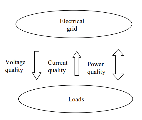
The electrical power grid or network should be designed in such a way that the supplier is always capable of guaranteeing a certain voltage quality. When loads are connected the power quality is influenced more or less depending on how the electrical network is designed and on the current profile of the loads. From this perspective, a number of basic parameters for power quality have been identified which can be measured and compared with reference values. The reference values may be absolute values or statistical values and may be obtained from standards or agreed in a bilateral contract between network generator and a customer.
For instance, a well recognised European norm is EN 50 160: Voltage characteristics of electricity supplied by public distribution systems [3], in which the parameters registered and being compared are the voltage magnitude, frequency, harmonic distortion, voltage unbalance, flicker, signaling voltages. EN 50 160 does not give any voltage characteristics for events like voltage dips, swells, transients etc. However, for the completeness a list of various events is mentioned together with indicative values. Note however that EN 50160 is not so much a requirement for the voltage quality but a description of the existing situation. The term “voltage characteristic” refers to the level not exceeded by 100% of customers during 50% of time. It is thus obvious that most locations have a voltage quality that is “better than the standard”. Measurements against the standard are only of use when this is taken into consideration.
III. DIFFERENT CATEGORIES OF POWER QUALITY MEASUREMENTS
Measurements in the power network can be split into different categories. The most common ones are demand analysis (power and energy measurements), measurements to detect disturbances, statistical measurements about the electrical grid, measurements according to standards (EN 50160 etc.) and measurements to be able to design components like transformers, capacitor bank filters etc. The various categories of measurement require different instruments.
With the increasing needs for PQ measurement, there is a growing need for standardisation. The future standard IEC 61000-4-30 will set a new benchmark for power quality measurements and will be important for both users and manufacturers of PQ instruments.
IV. CLASSIFICATION OF POWER QUALITY PARAMETERS
For the average user it is normally difficult to compare instruments. Will the instrument produce reliable results that are comparable with those from other makes? The longer the technical specification, the better, is a common approach. Unfortunately this has little to do with customer driven requirements. Here, IEC 61000-4-30 is offering a solution by classifying the power quality parameters into class A (Normative) and B (Indicative).
Instruments measuring for class B are used specifically for demand analysis and simple error search. They can be either single-phase or three phase with limited accuracy of say +/-1% per channel. Furthermore the indicative power network monitor measures only partly or not at all against given standards. However, the manufacturer of class B instrument shall define the measurement methods used.
Instruments that measure the power quality parameters according to class A are recognized as operating with the highest possible accuracy in all measuring environments/situations. The normative instrument can be used for the same kind of measurement as the indicative instrument but is especially designed to carry out normative measurements against recognised international or local standards or contracts.
Measurements made according to class A are required when verifying standards and when it comes to disputes between customer and supplier and when measurements have to be compared with those from other instruments.
What this means is that measurements that have been done with two different instruments according to class A will give the same result within the accuracy indicated in the standard. Instruments that measure according to class B only give indicative results, dependent on the method used to calculate the parameters, so that measurements taken at the same measuring point but with two different instruments could give different results. Class B instruments can be used for demand analysis, some easier disturbance trace measurements but only with measurements that do not demand an absolute accuracy. Therefore, a class A instrument will always be able to replace a class B instrument but not vice versa.
V. CHANGING DEMANDS FOR POWER QUALITY MEASUREMENTS
Considering electrical energy as a product it is self-evident that it must be quality assured. Traditionally this has been carried out by occasional short-term power quality measurements at isolated locations on the network using portable recorders. Some of these instruments produced reams of paper based data, which was hard to store and analyse. The application of modern electronics to high-speed data acquisition, signal processing, storage and analysis enables a more comprehensive and user-friendly approach from which a new trend is emerging.
IEC 61000-4-30 contains guidelines for contractual applications of power quality measurements. Whilst most parameters can be assessed over a survey period of one week, assuming no abnormal conditions occur such as severe weather, industrial action, third party interference, etc., voltage sags and swells must be assessed over a much longer period – one year is suggested. This makes sense, as dips are generally caused by faults on the network or customer’s installations – they are unpredictable, largely random and their distribution over a year can be very irregular. The implication for monitoring is profound.
A temporary survey using a portable analyser will be inadequate to monitor contractual obligations and permanent instrumentation will be required; especially since voltage dips are one of the most commonly complained about phenomena.
The following examples show how the application of permanent monitoring systems has been successfully used to tackle power quality issues.
A. Power Quality Monitoring on Wind Generators in Ireland
The number of wind generators in Ireland is rapidly increasing due to the suitability of the environment for this kind of power generation. In the southern part of Ireland, near the city of Cork, large wind generators can be seen, dotted around the countryside. However, it is well known that wind generators can cause power quality problems, particularly an increased level of flicker. In order to prevent PQ problems ESB (Eire Supply Board), one of the main suppliers of electricity in Ireland, has decided to install permanent power quality monitoring equipment in substations connected to the generators. The first batch of eighteen monitors is now working and more installations are planned. Not only the flicker, but also other important PQ parameters like sags, swells, transients are continuously monitored and measured data are regularly downloaded to the host computer via an ordinary modem or via a GSM modem for evaluation and presentation.
B. Co-operation between the local distributor and industry regarding power quality monitoring
The city of Linköping in Sweden has approximately 150,000 citizens. It is well known for its university as well as the large industry plants. The utility in Linköping was one of the first to install a permanent power quality monitoring system. It started as a quality issue with the university hospital in Linköping. Since the hospital has a lot of critical equipment, they were very concerned about the quality of their power supply. In cooperation with the utility, permanent power quality monitoring equipment was installed in the substation feeding the hospital. Today, the electrical power supplied to the hospital is fully quality assured.
In addition, the large industry plants were concerned about power quality. A mobile-phone plant and an aerospace plant have installed their own permanent power quality monitors, out-sourcing the evaluation of the measurements to the local utility on a consultant basis. This co-operation has indeed strengthened the relationship between the utility and the customer.
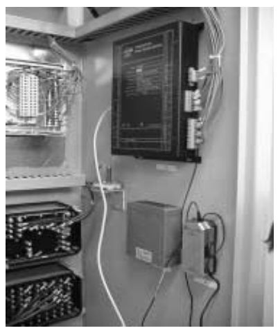
Success of the above projects and others has led to a mix of permanently installed power quality monitors and portable power network analysers. The permanently installed monitors continuously register the power quality at strategic locations in the electrical grid such as bulk supply points including transmission terminal stations and zone substations, as well as other important connection points to key customers – see Fig.2. Measured data is then transferred automatically, via LAN or modem, to a database where evaluation takes place against reference standards and norms and variations reported by exception.
Portable power network analysers are still used for occasional measurements at locations where no permanent monitors are installed, but these are now available with communication facilities and their measurements are integrated into the database. The control of power quality is becoming a fundamental and strategically important part of the electrical power suppliers’ quality assurance program. New business opportunities are being created based on guaranteeing a certain level of power quality. One opportunity is to be able to offer adjusted power quality to meet the customer’s particular demand and therefore get paid accordingly. This is something which has started to happen in the US and which is generating interest in the European market as well.
VI. THE FUTURE STANDARD IEC 61000-4-30
Now that the practical implications of the standard have been detailed, the following information provides an introduction to the forthcoming IEC 61000-4-30. For a more detailed description, refer to the original document [4].
“Measurement methods are described for each relevant type of parameter in terms that will make it possible to obtain reliable, repeatable and comparable results regardless of the compliant instrument being used, and regardless of its environmental conditions. This standard addresses instrumentation and measurement methods for in-site measurements, and applies to both portable and permanently installed instrumentation.” (IEC 61000-4-30; 1. Scope; p.9.)
The power quality parameters described are power frequency, magnitude of the supply voltage, flicker, supply voltage sags (dips) and swells, voltage interruptions, transient overvoltages, supply voltage unbalance, voltage and current harmonics, voltage interharmonics and mains signaling on the supply voltage and rapid voltage changes.
A. Class A and Class B
The standard describes how the power quality parameters fulfilling class A shall be calculated. For class B instruments, there are no restrictions as to how the parameters shall be calculated but the manufacturer shall specify the measurement methods used.
The following sections provide an overview of the relevant standards for class A instrumentation. To increase the readability of the text below, only 50 Hz are considered. Below discussions are valid also for a 60 Hz system.
B. Integration Times
For class A, the time integration window when recording shall be 10 cycles in a 50 Hz system. With this time integration window as a base, three measuring intervals are defined. These are 150 cycles, 10 minutes and 2 hours. The 150 cycles RMS value is calculated as the root mean square of fifteen 10 cycles RMS values. The windows shall be continuous and non-overlapping so it is easy to proof that the calculated 150 cycle value is the correct RMS value obtained. The aggregation from 150 cycles to 10-minutes is more complicated since the actual frequency will vary. When the system frequency is exactly 50 Hz, there are exactly 200 intervals. For a frequency of 49.5 Hz the 150 cycles become 3.03 seconds and there will be only 198 of them in a 10-minute interval. In most cases the number of intervals is not an integer number and the last interval is discarded in the calculation. Despite the discarded data, it remains safe to interpret URMS(10-min) as the RMS voltage over a 10-minute interval.
Each 10-minute interval must begin on an absolute 10- minute time clock, ± 20 ms. These intervals are used when calculating the voltage magnitude, harmonics and interharmonics and the voltage unbalance.
For frequency measurements a 10-seconds interval is used. There is no aggregation of frequency measurements.
C. Flagging concept
The ”flagged” concept avoids the counting of a single event more than once for different parameters, e.g. counting a single dip as both a dip and a frequency variation. When an event such as voltage dip, swell or a short interruption occurs the instrument shall only record that specific event. The other power quality parameters shall not be recorded. Instead, the interval will be flagged, meaning that it is marked to show the specific event and no other measured data. If a flag is set for a 10 cycles time window interval then the associated 150 cycles, 10 minutes and the 2 hours measurement intervals will also be flagged.
D. Frequency
The frequency shall be calculated every 10 second for class A instrument. To calculate the frequency the number of zero-crossings during 10 seconds is counted. The accuracy for class A shall be better or equal to ± 10 mHz and less than ±100 mHz for class B.
The frequency can be calculated by measuring the elapsed time between the first and the last voltage zero crossing within the 10-second interval. Let N be the number of zero-crossings within the interval and T the elapsed time, the frequency is obtained from:
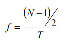
Assuming that the value of N is correct, an accuracy of 10 mHz (2⋅10-4 of 50 Hz) requires an accuracy of 2⋅10-4 in the time measurement: 2 ms on 10 s.
E. Voltage RMS value
The voltage RMS value is calculated for every 10 cycles interval for class A instruments. Based on this 150 cycles, 10 minute and 2 hour interval values can be calculated. As shown in Section VIB the values can be interpreted as the RMS voltage over 10-cycles, 150-cycles, 10-minute, and 2-hour intervals. The accuracy for class A shall be better or equal to ± 0.10 % of nominal voltage and for class B ± 1.0 %.
F. Flicker
The flicker calculations for class A instruments shall follow the restrictions according to the norm IEC 61000- 4-15 (Flickermeter – functional and design specifications) [5].
G. Voltage dips (sags) and swells
The registration of sag/swell events shall be based on 1 cycle RMS values updated every ½ cycle for class A instruments. When this RMS value exceeds or fall below a stated triggering level, the instrument shall start recording and continue until the RMS values have returned to normal. The first instant is referred to as the start of the event, the second as the end of the event. The time between the start and the end of the event is called the duration of the event. The lowest RMS value for a voltage dip is called the retained voltage. The accuracy for class A instruments shall be within ± 0.2 % of the stated nominal voltage and ± 2.0 % for class B.
H. Unbalance
To fulfil the restrictions of class A, unbalance shall be calculated using the method of symmetrical components. From the measured phases, the three symmetrical components are calculated (positive-, negative- and the zero sequence component). The unbalance is then calculated as the ratio between the negative and the positive sequence component expressed as a percentage. Unbalance shall again be calculated over 10-cycle, 150- cycle, 10-minute and 2-hour intervals.
I. Voltage harmonics (harmonics and interharmonics)
To fulfil the requirements for class A the calculations shall be made according to IEC 61000-4-7. For a more detailed description see IEC 61000-4-7 (General guide on harmonics and interharmonics measurements and instrumentation, for power supply systems and equipment connected thereto) [6]. The basic interval for harmonic measurements is again the 10-cycle interval. A DFT (Discrete Fourier Transform) over a 10-cycle window gives a spectrum with a frequency resolution of 5 Hz. This implies that in between the harmonic frequencies (integer multiples of 50 Hz), nine additional values are available. The lowest and the highest of these are “added” to the (integer) harmonic. The remaining seven together form the “interharmonic”. Thus for the interval from 245 Hz to 305 Hz: 255 Hz is added to 250 Hz and 245 Hz to form the 5:th harmonic; 295 Hz, 300 Hz and 305 Hz form the 6:th harmonic. The remaining values: 260, 265, 270, 275, 280, 285 and 290 Hz form “interharmonic 6.5”.
J. Other power quality parameters
The above descriptions provide an introduction to the type of requirements stipulated by the forthcoming standard. For a description of other parameters, such as how transient overvoltages, rapid voltage changes, short voltage interruptions and signaling voltages shall be calculated see the original document IEC 61000-4- 30:2001.
VII. OTHER DEVELOPMENTS
Next to IEC, power quality standards are also developed within IEEE. In 1997 did both the IEEE Gold Book and IEEE Std.1346 give a method for assessing the compatibility between sensitive equipment and supply as far as voltage dips are concerned. The so-called “voltage sag co-ordination chart” enables a direct comparison between equipment voltage tolerance and the voltage dip frequency of the supply [7]. Work on interruptions and reliability has been part of an IEEE standard (recommended practice) since the publication of the first IEEE Gold Book in 1980. The most recent version (1997) even includes a chapter on stochastic prediction of voltage dips. However the IEEE never published a document on measurement of voltage quality. Project Group 1159 is working on such a document, but as yet without much concrete results. The most recent decision is to use IEC 61000-4-30 also within IEEE.
Recently a standard appeared on reliability indices (IEEE Std.1366) which recommends methods for quantifying the reliability of the supply (number and duration of long interruptions). Similar indices are currently under development in IEEE Project Group 1564. The most recent version of the working document of this group uses IEC 61000-4-30 as a basis and from here defines different levels of voltage dip indices.
The first level is formed by “event characteristics as a function of time”. The one used within IEC 61000-4-30 is the one-cycle RMS voltage updated every half cycle. The IEEE document aims at defining some additional event characteristics. From the event characteristics so-called “single-event indices” are calculated. In the case of IEC 61000-4-30 these are “duration” and “retained voltage” for voltage dips. Again some additional indices are defined.
The next level is formed by the “single-site indices”: typically the number of events per year within certain ranges of single-event indices: like the number of dips per year with a duration exceeding 100 ms and a retained voltage below 70%. The final level is the “system indices” being typically a weighted average of the single-site indices of all the monitor locations [8].
Work on power-quality indices (not just voltage dips but also harmonics, unbalance and harmonics) is also ongoing in CIGRE Working Group 36.07. This working group concentrates on the definition of appropriate system indices starting from existing standard documents. The working group also collects data to propose objectives for the indices.
VIII. CONCLUSIONS AND COMMENTS
Today, there are many types of power quality instrument on the market offering different performance according to their measurement techniques. In many cases the users are not aware of this and it is common for them to be misled, believing that results always are reliable and that measurements from different instruments always can be comparable. Unfortunately this is not always the case. Measured results from different power quality instruments are often not fully comparable against either another instrument or even against existing standards. With the increasing demand for accurate power quality supervision in the electrical network it is important that an international standard states how power quality should be measured and calculated, so that valid comparison is possible. This is particularly true for power companies and their customers entering into contractual relationships for the delivery of an assured quality of supply.
One step in this direction is the forthcoming IEC 61000-4- 30 norm (standard) that defines measuring methods and provides new ways to classify power quality instruments. The standard will lead to manufacturers of power quality instruments implementing the same measuring algorithms. Furthermore, it will be important for the end user giving them the full knowledge about instrument performance. IEC 61000-4-30 will therefore be beneficial for both manufacturers and users of power quality instruments.
IX. REFERENCES
[1] Axelberg P, Pool G, 2000, “Experiences from the deregulated electricity markets in South America”. Nordic Distribution Automation Conference.
[2] Bollen M.H.J, 2000, “Understanding Power Quality Problems”. New York: IEEE press. ISBN 0-7803-4713-7,.
[3] European norm EN 50 160: Voltage characteristics of electricity supplied by public distribution systems. CENELEC 1999
[4] IEC standard 61000-4-30:2001 (draft): Testing and Measurement Techniques- Power Quality Measurement Methods.
[5] IEC standard 61000-4-15: Flickermeter – functional and design specifications. IEC 1999.
[6] IEC standard 61000-4-7: General guide on harmonics and interharmonics measurements and instrumentation, for power supply systems and equipment connected thereto. IEC 2001.
[7] Bollen M.H.J, Conrad L.E., “Voltage sag coordination for reliable plant operation”, IEEE Transactions on Industry Applications, Vol.33, No.6, pp.1459-1464.
[8] IEEE, 2001, ”Voltage sag indices”. Working document for Project Group 1564, draft 2. http://grouper.ieee.org/groups/sag/.
X. BIBLIOGRAPHIES
Peter Axelberg is a senior lecturer at Högskolan i Borås, Sweden. His research activities are focused on power quality measurement techniques. He is also one of the founders of Unipower AB.
Math H. J. Bollen is professor in electric power systems at Chalmers University of Technology. Before joining Chalmers in 1996 he worked at UMIST, Manchester, UK and at Eindhoven University of Technology in The Netherlands. His research activities include various aspects of power quality. Math is co-chair of IEEE P1564 and member of CIGRE WG 36.07.
Source URL: https://www.unipower.se/wp-content/uploads/2022/10/cired2002_paper.pdf
