Published by Machmud Effendy1, Dandy Dwi Saputra1,Fourys Yudo Setiawan Paisey2,
Department of Electrical Engineering,University of Muhammadiyah Malang, Indonesia (1)
Department of Electrical Engineering, University of Papua Manokwari, Indonesia (2)
Abstract. Centralized generation centralized storage architecture (CGCSA) and distributed generation distributed storage architecture (DGDSA) are two operation of the proposed scheme, both architectures are evaluated at different distribution voltage levels. Power flow of both architectures was analyzed using the Newton Raphson Method. DGDSA has advantages over CGCSA because the voltage drop on the bus is lower, the system efficiency is higher, and the power loss on the line is lower.
Streszczenie. Architektura scentralizowanej generacji scentralizowanej pamięci masowej (CGCSA) i architektura rozproszonej generacji rozproszonej generacji rozproszonej (DGDSA) to dwie operacje proponowanego schematu. Obie architektury są oceniane przy różnych poziomach napięcia dystrybucyjnego. Przepływ mocy w obu architekturach analizowano metodą Newtona Raphsona. DGDSA ma przewagę nad CGCSA, ponieważ spadek napięcia na magistrali jest niższy, wydajność systemu jest wyższa, a straty mocy na linii są mniejsze. (Analiza przepływu mocy generacji rozproszonej i rozproszonej pamięci masowej (DGDC) w mikrosieci prądu stałego przy użyciu metody Newtona Raphsona)
Keywords: power flow, distributed generation distributed storage, newton raphson
Słowa kluczowe: przepływ mocy, generacja rozproszona, rozproszona pamięć masowa, Newton Raphson
Introduction
Utilization of direct current (DC) has been widely explored. It aims to serve most modern loads more efficiently that require DC power. Thus, it is necessary to have an alternating current (AC) to DC conversion stage when powered from a distribution network conventional power [1,2]. In addition, the source of electrical energy from renewable energy continues to increase to replace fossil energy which causes pollution and pollutes the environment. Thus, distributed generation as an independent renewable power plant connected to the distribution network is also increasing [3].
Distributed generators form a microgrid electrical system that has various types of networks including radial, ring, and others that have different functions in power flow analysis [4]. The microgrid system consists of a DC microgrid and an AC microgrid. DC microgrids have several advantages, including higher efficiency, simpler control models, less cost and the absence of reactive power, frequency and phase [5,6]. Furthermore, the design of the power distribution system requires a power flow analysis to determine the quality of the electricity. Likewise, the DC microgrid system requires power flow analysis for system optimization during the planning and operational stages of the electrical architecture [7,8].
The electrification architecture for isolated DC microgrids consists of central generation-central storage (CGCS) and distributed generation-distributed storage (DGDS). Centralized resources are generally very beneficial when viewed from the control system because all generating and storage performance can be monitored from one location, so that the reliability of the monitoring system can be increased. However, the emergence of higher distribution losses and the difficulty of future expansion are CGCSA’s weaknesses [9,10]. This architecture is still less than optimal in two respects: (a) centralized PV generation requires higher initial costs due to the large power capacity for solar panels, and b) significant system losses due to distribution of electricity to distant houses. [11,12]
Given the limitations of the previous dc microgird architecture such as (a) distribution efficiency, (b) expansion that is not easy in the future, and (c) requirements extensive control in the region. Next, we propose a distributed generation and distributed storage architecture (DGDSA) with ring interconnection. To prove the performance of this architecture, power flow will be analyzed using the newton raphson method.
DC Microgrid Model
The proposed DC Microgrid system is an independent electrical interconnection system, where this system is capable of generating, storing and distributing electricity to loads. Solar PV is the main energy source, other generation sources can be integrated with DC microgrids because the topology presented is universal. For example, a generator from wind power can be combined with a microgrid via a rectifier circuit. However, for the scope of the study, only PV sources were considered.
Distributed Generation Distributed Storage Architecture
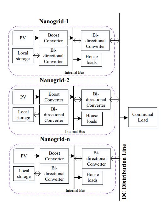
The proposed electrical architecture is a distributed generation and distributed storage (Fig. 1). Households are the basic building that represents a nanogrid. Each house is capable of generation, storage and bi-directional power flow. A combination of several nanogrids that can share resources can be defined as a DGDSA in a DC Microgrid network so that the balance of load power is fulfilled and even communal loads can also be supplied together.
Figure 1 explains that a nanogrid can be modeled by combining PV, household loads, local battery storage, boost converters, and bidirectional buck-boost converters. Boost converters are required in solar panels due to the non-linear voltage-current output characteristics, so maximum power point tracking (MPPT) is considered. Literature [13, 14] describes several MPPT methods to maximize PV output power. In this study, the DGDSA topology uses MPPT Perturb and Observe (P&O) because the system design is simpler and the convergence point is reached more quickly [15]. Batteries are employed as a storage system to give the required autonomy.
When the load varies, the bidirectional buck-boost converter is responsible for converting the bus internal voltage to grid level voltage or vice versa. Thus, bidirectional flow of power can contribute to providing flexible electricity to DGDSA. Through this bidirectional system, the household load can be supplied, the battery can be charged, and the remaining power in the house can be injected directly into the electricity grid.
DC Microgrid Scheme of Interconnection
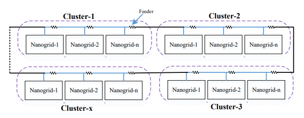
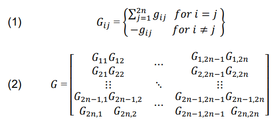
The microgrid DC network system has several clusters, where each cluster has several nanogrids, as shown in Fig. 2. The interconnection resistance between two nanogrids models the feeder resistance. The ring interconnections between nanogrids are illustrated in Fig. 2. Interconnection ring that uses an additional conductor layer (dashed line) is also shown in figure 2, so that this interconnection can connect feeders at the edge of the interconnection network in a circular manner. Thus, higher efficiency and increased reliability can be achieved by adding additional conductors, even in low-voltage distribution networks. The conductance matrix G can be constructed using feeder resistance values depending on the connectivity scheme and topological topology of a cluster. G is of the order 2n x 2n for a cluster with n nanogrids since there are two buses per nanogrid: internal bus and eksternal bus. Thus, members of the conductance matrices Gij and G can be represented in terms of individual conductance gij between any two buses i and j, where i might range between 1 and 2n:
Newton Raphson Method for Power Flow Analysis
The desired voltage level and power efficiency in the operation of the DC Microgrid electricity network are determined using power flow analysis. Power flow analysis in conventional AC power systems often employs a variety of techniques, including Gauss-Seidel (GS), Newton Raphson (NR), and Fast decoupling [16,17]. For the analysis of DC power flow, a Newton-Raphson approach is described in this paper [8]. The proposed power flow method is used to analyze several important parameters such as line loss, efficiency and voltage drop.
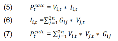
Depending on the load requirements, the power required for each load on each bus is scheduled by this equation:
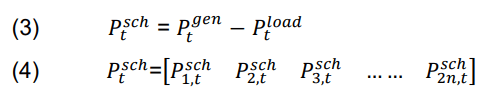
After determining the power required for each subsequent load, the instantaneous power can be calculated using the bus voltage and the total current flowing to each bus with the following mathematical formula.
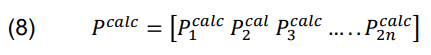
Next, equation (8) shows the Pcal load matrix:
Furthermore, equation (4) is subtracted from (8) by expanding the remaining terms using the Taylor series ignoring high-level terms, and equation (10) is obtained [8]:
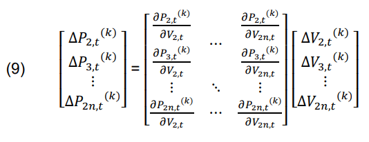
∆𝑃i(k) represents the difference between the scheduled powers 𝑃isch and 𝑃ical on bus i at the kth iteration. The term ∆𝑉i,t in the matrix explains that there is a change in the voltage of the bus in each iteration. Then, the voltage on each bus is updated by adding 𝑉i,t and the voltage ∆𝑉i,t from the previous iteration until convergence is obtained. This convergence is the voltage value used to find the power losses LLg(t) and the percentage of power losses %LLg(t). Power losses and their percentages can be can be calculated mathematically as in the formula below.
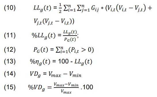
Vmax and Vmin represent the maximum and minimum values of voltage at any bus after kth iteration.
Result and Discussion
A remote area with 20 houses was utilized to test the proposed methodology. Each house has a maximum PV generation capacity of 250 WP at 1000 W/m2 radiation, battery with an energy capacity of 100 Ah. DC loads that can be operated include lighting, fans and charging. The village is divided into four clusters with five houses per cluster.
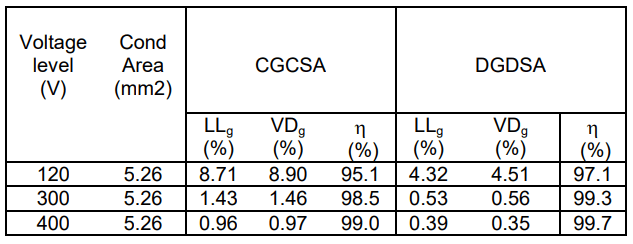
The proposed architecture applies Newton Raphson Analysis to evaluate its power efficiency, voltage level on a particular conductor. System performance is analyzed on 120V, 300V and 400V voltage distribution networks. The length of the conductor between neighboring houses is assumed to be 20m, while the length of the conductor between clusters is 200m. The cross-sectional area for the conductor i.e. 5.26mm2 is evaluated. For the DGDSA scenario, %LLg, %ɳg and %VD are calculated using (12) (14) (15).
In this scenario, some homes produce electricity in excess of load requirements, so the remaining electricity is injected into the power grid, while other homes will consume more electricity than the rated power, thereby absorbing electricity from the power grid. Microgrids act as a bridge between homes that overproduce electricity and homes that absorb electricity.
Table 1 shows the results of calculating the percentage of line loss, percentage of voltage drop and efficiency of DGDSA at peak load. Table 1 illustrates that the higher the bus voltage, the greater the distribution voltage efficiency. Safety and protection requirements up to 120V are not excessive [19,20]. In addition, bus voltages less than 120 V do not require additional grounding and protective conductors, and these voltages are safe for indirect contact, [19]. From the results of table 1, it can be concluded that DGDSA has higher efficiency than CGCSA because the electricity sources are spread out and the ability to share resources.
Table 1. Peak load comparison between CGCSA and DGDSA
Conclusions
This research presents an analysis of distributed and centralized systems for DC microgrids. DC power flow analysis (CGCSA and DGDSA) is calculated using the Newton Raphson method, so that the percentage of voltage drop, percentage of line loss, and power efficiency can be known. The analysis results show that the proposed distributed generation and storage architecture can improve distribution efficiency by close to 4% compared with centralized architecture. Furthermore, DGDSA has smaller line losses and less voltage drop than CGCSA.
REFERENCES
[1] M. Effendy, Ashari, M., & Suryoatmojo, H. (2022). Load Sharing and Voltage Restoration Improvement in DC Microgrids with Adaptive Droop Control Strategy. International Journal on Engineering Applications, 10(4), 233–240.
[2] F. S. Al-Ismail, “DC Microgrid Planning, Operation, and Control: A Comprehensive Review,” IEEE Access, vol. 9, pp. 36154–36172, 2021.
[3] M. Effendy, M. Ashari, and H. Suryoatmojo, “Performance Comparison of Proportional-Integral and Fuzzy-PI for a Droop Control of DC Microgrid,” Proceeding – 2020 Int. Conf. Sustain. Energy Eng. Appl. Sustain. Energy Transp. Towar. AllRenewable Futur ICSEEA 2020, pp. 180–184, 2020.
[4] Nasir, M., Khan, H. A., Hussain, A., Mateen, L., & Zaffar, N. A. (2018). Solar PV-based scalable DC microgrid for rural electrification in developing regions. IEEE Transactions on Sustainable Energy, 9(1), 390–399.
[5] Y. Xia, M. Yu, P. Yang, Y. Peng and W. Wei, Generationstorage coordination for islanded DC microgrids dominated by PV generators, IEEE Trans. Energy Convers., vol.34, no.1, pp.130-138, 2019.
[6] R. Kumar and M. K. Pathak, Distributed droop control of DC microgrid for improved voltage regulation and current sharing, IET Renew. Power Gener., vol.14, no.13, pp.2499-2506, 2020.
[7] Hesaroor, K., & Das, D. (2020, December 10). Improved Modified Newton Raphson Load Flow Method for Islanded Microgrids. 2020 IEEE 17th India Council International Conference, INDICON 2020.
[8] Liu, Z., Zhang, X., Su, M., Sun, Y., Han, H., & Wang, P. (2020). Convergence analysis of newton-raphson method in feasible power-flow for dc network. IEEE Transactions on Power Systems, 35(5), 4100–4103.
[9] M. Mehdi, C. H. Kim, and M. Saad, “Robust centralized control for DC islanded microgrid considering communication network delay,” IEEE Access, vol. 8, pp. 77765–77778, 2020.
[10] R. Zhang, A. V. Savkin, and B. Hredzak, “Centralized nonlinear switching control strategy for distributed energy storage systems communicating via a network with large time delays,” J. Energy Storage, vol. 41, no. February, p. 102834, 2021.
[11] J. Kumar, A. Agarwal, and V. Agarwal, “A review on overall control of DC microgrids,” J. Energy Storage, vol. 21, pp. 113–138, 2019.
[12] Saleh, M., “Esa Yusef, & “Mohamed, A. (2017). Centralized Control for DC Microgrid Using Finite State Machine. 2017 IEEE Power & Energy Society Innovative Smart Grid Technologies Conference (ISGT), 1–5.
[13] Li, X., Wang, Q., Wen, H., & Xiao, W. (2019). Comprehensive Studies on Operational Principles for Maximum Power Point Tracking in Photovoltaic Systems. IEEE Access, 7, 121407–121420.
[14] Bollipo, R. B., Mikkili, S., & Bonthagorla, P. K. (2021). Hybrid, optimal, intelligent and classical PV MPPT techniques: A review. In CSEE Journal of Power and Energy Systems (Vol.7, Issue 1, pp. 9–33). Institute of Electrical and Electronics Engineers Inc.
[15] Bhattacharyya, S., Kumar P, D. S., Samanta, S., & Mishra, S. (2021). Steady output and fast tracking MPPT (SOFT-MPPT) for P&O and InC algorithms. IEEE Transactions on Sustainable Energy, 12(1), 293–302.
[16] Montoya Giraldo, O. D. (2019). On Linear Analysis of the Power Flow Equations for DC and AC Grids with CPLs. IEEE Transactions on Circuits and Systems II: Express Briefs, 66(12), 2032–2036.
Authors: Machmud Effendy, Department of Electrical Engineering, University of Muhammadiyah Malang, Indonesia, e-mail : machmud@umm.ac.id Dandy Dwi Saputra, Department of Electrical Engineering, University of Muhammadiyah Malang, Indonesia, email : dandysaputra218@gmail.com Fourys Yudo Setiawan Paisey, Department of Electrical Engineering, University of Papua Manokwari, Indonesia, email : paiseyfourys75@gmail.com
Source & Publisher Item Identifier: PRZEGLĄD ELEKTROTECHNICZNY, ISSN 0033-2097, R. 100 NR 2/2024. doi:10.15199/48.2024.02.16
