Published by Ruchika, D.K. Jain, DCRUST, Murthal, Haryana
Abstract. Battery energy storage system (BESS) plays a dominant role in large scale penetration of renewable energy sources into the grid. They help in a better match between the demand- supply during standalone mode and the grid connected mode. In this paper, the authors proposed a new approach for improving the availability of the solar generation by using BESS during the period of intermittency. The BESS supports the grid during intermittency by an amount of power, which has been promised by the operator. Thus, whatever the operator bids will be supplied to the grid either using renewable energy generation or if not available, then BESS will support the grid. The paper also discusses the role of BESS for smoothing of PV power. Matlab software is used for all the simulation experiments.
Streszczenie. Bateryjny system magazynowania energii (BESS) odgrywa dominuj ˛ac ˛a rol ˛e w przenikaniu na du ˙z ˛a skal ˛e odnawialnych ´zródeł energii do sieci. Pomagaj ˛a w lepszym dopasowaniu popytu do poda ˙zy w trybie autonomicznym i trybie podł ˛aczonym do sieci. W artykule autorzy zaproponowali nowe podej ´scie do poprawy dost ˛epno ´sci generacji słonecznej poprzez wykorzystanie BESS w okresie nieci ˛agło ´sci. BESS wspiera sie ´c w przerwach w ilo ´sci mocy, któr ˛a obiecał operator. Tak wi ˛ec niezale ˙znie od tego, co operator zaoferuje, zostanie dostarczone do sieci za pomoc ˛a wytwarzania energii odnawialnej lub je ´sli nie b ˛edzie dost ˛epne, wówczas BESS b ˛edzie wspiera ´c sie ´c. W artykule omówiono równie ˙z rol ˛e BESS w wygładzaniu mocy PV. Do wszystkich eksperymentów symulacyjnych wykorzystywane jest oprogramowanie Matlab. (Akumulatorowy system magazynowania energii do penetracji Odnawialnych Zródeł Energii na du ˙ ´ z ˛a skal ˛e)
Keywords: Battery Energy Storage System (BESS), Photovoltaic (PV), Solar Energy
Słowa kluczowe: Słowa kluczowe> System Magazynowania Energii (BESS), Fotowoltaika (PV), Energia Słoneczna
Introduction
Renewable energy growth and development has now become a basic requirement for growth of a country [1], [2], [3]. For a better environment, renewable energy is seen as a replacement for conventional fossil fuel based generation. Although, there has been a lot of work in the field of renewable energy however, there are still various reasons because of which renewable energy still shares a very small amount of energy with respect to the total energy generation [4]. The renewable energy sources, such as wind, solar, biomass, ocean etc may work in standalone as well as grid connected mode. The major issue with these sources is the intermittent nature of these sources [5], [6]. They are basically dependent upon environmental conditions such as availability of sun, wind and temperature, pressure etc. When there is a cloudy condition the sun is not available and solar energy generation may go down, sometimes even to zero. The surety of power to consumers is one of the basic requirements for energy system operators [7]. To deal with the intermittency nature of these renewable sources, battery energy storage systems (BESS) are used in various power stations [8], [9], [10], [11]. However, BESS has its own advantages and disadvantages. BESS may help in providing the power to consumers during intermittency; however it is sometimes not capable of transients arising during the switching conditions [12], [13], [14], [15]. And BESS are also very expensive and have high installation costs [16], [17]. In grid connected mode, BESS may not be needed as whatever the deficit power is, it may be fed by the grid.
However in the present scenario, the grid also possesses stringent grid codes and one of them is the surety of power which is being promised by a private operator during bidding [2], [18], [19]. Thus, BESS now becomes important in grid connected mode also as during intermittency it may have to provide the power to grid in order to fully fill the amount of power which is being promised during competitive bidding. Since, BESS is now an integral part of renewable energy generation in both grid connected and standalone mode, its sizing and analysis based on the capacity of the plant is an area of research [20], [21], [22].
In this paper, a new approach is proposed for improving the availability of the solar generation by using BESS during the period of intermittency. The BESS supports the grid during intermittency by an amount of power, which has been promised by the operator. Thus, whatever the operator bids that will be supplied to the grid either using renewable energy generation or if not available, then BESS will support. The paper also discusses the role of BESS for smoothing of PV power. The simulation work is done in MATLAB. In this paper, Section – II discusses the proposed energy management for grid scale application of BESS. Section -III discuss the test system undertaken. Section IV presents the results and discussions. Section – V concludes the paper.
Energy Management for Grid Scale Application of BESS
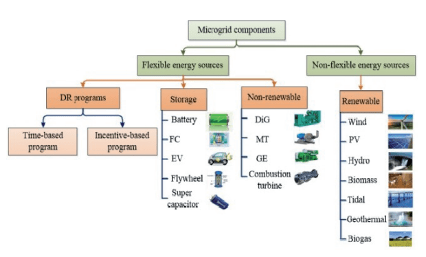
The microgrid concept is introduced to have a selfsustained system consisting of distributed energy resources that can also operate in an islanded mode during grid failures. Thus, the energy management system (EMS) may serve a variety of purpose depending upon the application of BESS during the grid connected and standalone mode of operation such as power smoothing, power quality improvement, matching supply and demand, supplying energy to grid if bid power is greater than generation etc. Over the last decade, EMS have been researched considering various perspectives and have attracted the attention of researchers. EMSs have been classified into four categories as shown in Fig.1 based on the kind of the reserve system being used, including non-renewable, ESS, demand-side management (DSM) and hybrid systems.
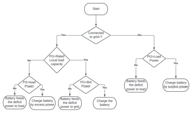
The proposed energy management system coordinates with the renewable energy generation, BESS, local load and power grid. It assumes that every individual plant has some onsite local load. Thus, the generating station is responsible for feeding the local load. This is done by feeding the load either from generation done by RES or if not available then the load will be fed by the battery. Thus, the generating plant has three functions (i) feeding the local load (ii) charging of BESS and (iii) selling surplus power to the grid. The energy management scheme considers the generation which is equal to the total local load rated capacity, as the power either used for feeding the load or if the load is less the its peak value then the rest of the power is utilised for charging the battery. Thus, whatever power is more than the rated local load capacity is considered as surplus power which may be sold to grid. An operator bids the power to be supplied to the grid on the basis of either predictions based on weather conditions or old trend of the generation. Its not necessary that the generation matches the bid power. Sometimes the generation may be higher and sometimes it be lower than the total generation. When the generation is higher than the bid power that power may also be used for charging of BESS, however, when the power is less than the bid power the battery is utilised to match the bid power. This, helps in maintaining the surety of power being promised by an operator. The proposed scheme is presented in the flowchart shown in Fig.2. When the system is in standalone mode, the generated power is utilised to feed the load and remaining surplus power is utilised to charge the battery. In case, the generated power is less than the load power, the battery support to handle the deficit power by feeding the load.
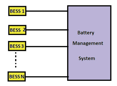
In this paper, a single unit of BESS and RES is implemented along with local load, which is in grid connected mode. Simulations are performed for standalone and grid connected mode both. The scheme is proposed for one such unit of microgrid, which may be easily extended for multiple microgird by using a battery energy management system as showin in Fig.3. Centralized BMS architecture has one central BMS in the BESS as hwon in Fig.3. All the battery packages are connected to the central BMS directly. The centralized BMS has some advantages. First, it is more compact. Second, the centralized BMS solution is the most economical since there is only one BMS. The main goal of BMS is to keep the battery within the safety operation region in terms of voltage, current, and temperature during the charge, the discharge, and in certain cases at open circuit. In this way, the battery will serve the application as long as possible in the most predictable way without creating any threat menacing the energy system and the nearby people (inhabitants, staff, maintenance, etc.). This part of BMS may be referred as charge and discharge management. Additionally, BMS may analyze the battery behavior in a continuous or periodic manner transforming the monitored parameters into battery state data which are fed to the upper system level or are directly used to control the charge and the discharge processes on a feedback principle. The upper system level can be the battery user itself (like a driver of an electric car) or a software/hardware configuration controlling the energy system. Depending on the obtained battery state data, the user can choose and execute a given decision which can be reduced often to a simple termination or restart of the charge or the discharge process.
Test System Description
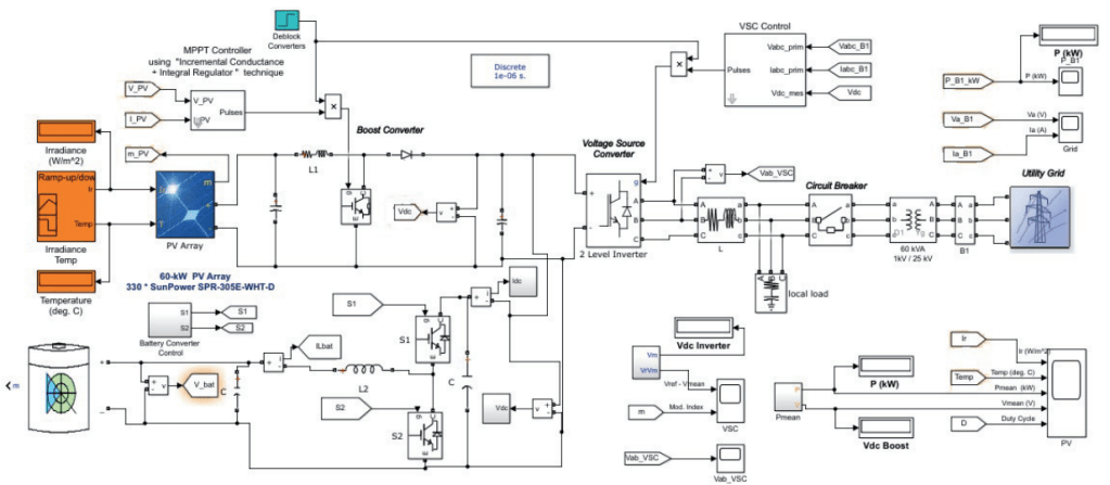
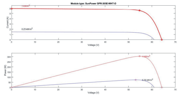
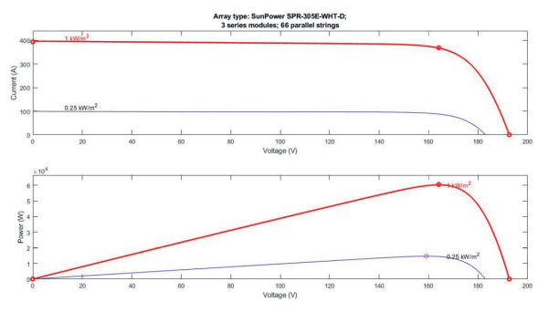
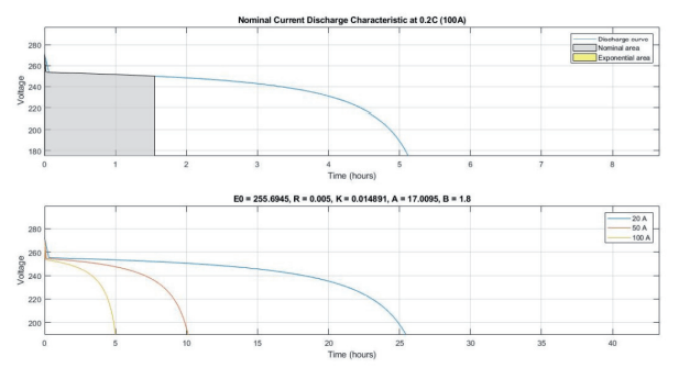
A small hybrid test microgrid is stimulated using MATLAB simulink platform, the test system model is shown in Fig. 4. The microgrid is composed of a 60 kW PV source using inbuilt 60kW Pv array SunPower SPR-305E-WHT-D module with 3 series module and 66 parallel strings. The solar PV characteristics for on module is shown in Fig. 5 and that for PV array having with 3 series module and 66 parallel strings is shown in Fig. 6. This PV module is connected to DC bus via a boost converter. PV generation is maximised with the help of maximum power points tracking (MPPT) at particular voltage for different values of irradiance and temperature. Incremental conductance based MPPT is applied to maximise the output power of PV module for a set of temperature and irradiance. In this method, the desired maximum power point depends upon the instantaneous conductance and incremental conductance. It is the point where the two values. Thus, this method measures the two conductance and compares them to track the point of maximum power, so when the two become equal, the solar PV operates at maximum power point. The algorithm tries to maintain the same during the operation. This algorithm is based on the observation that at the maximum power point, change in power with respect to the change in voltage is equal to zero. Thus, this PV module is connected to 1kV dc bus, from where it is connected to grid with the help of a two level voltage source converter. The output of two level voltage source converter is fed to a 20kW three-phase dynamic AC onsite local load. The PV module is also supported by a 250V, 500Ah battery module having an initial state of charge (SoC) = 30, which is also connected to the DC bus through a current controlled bidirectional DC/DC converter. The bi-directional converter help in two way flow of power. The nominal current discharge characteristics of the battery module at 0.2degC for a current of 20A, 50A and 100A is shown in Fig.7.
BESS plays an important role in energy management of microgrid in both the operation mode. During standalone mode its role is only to charge and discharge itself whenever there is any difference in generated power and load power. The surplus power generated during off peak hours is utilised to charge the BESS. While, during peak load hours, the BESS supports the microgrid by feeding the load utilising the stored energy. This balance needs to be made in order to maintain the voltage and frequency within the specified limits. During standalone operation, all the priority loads need to be served all the time. In the absence of storage device, load shedding is the only option. So to avoid load shedding battery is placed in the microgrid along with its control system. The decision of distinguishing between the priority of different loads is to be made judiciously by implementing proper control algorithm. In grid connected mode, the BESS now has many functions, like feeding the deficit amount of bid power to grid, smoothing of power and ramp rate control etc. In this paper, the test hybrid AC/DC test microgrid is connected to grid via a three phase circuit breaker as shown in Fig.4. The hybrid AC/DC test microgrid has the capability of operation in grid connected as well as standalone mode.
Results and Discussions
The hybrid AC/DC test microgrid which is shown in Fig. 4 is operated in both standalone mode and grid connected mode. The algorithm for energy management in both the grid connected an standalone mode of operation is shown in Fig.2. The microgrid is successfully operated in both the mode. the battery module is supporting not only during the standalone mode but also in grid connected mode whenever the bid power is more than the PV generation. The results and specific observations are presented and discussed in the next subsections, respectively.
0.1 Standalone Mode of Operation
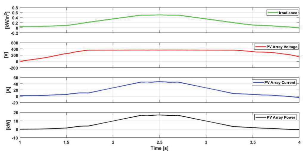
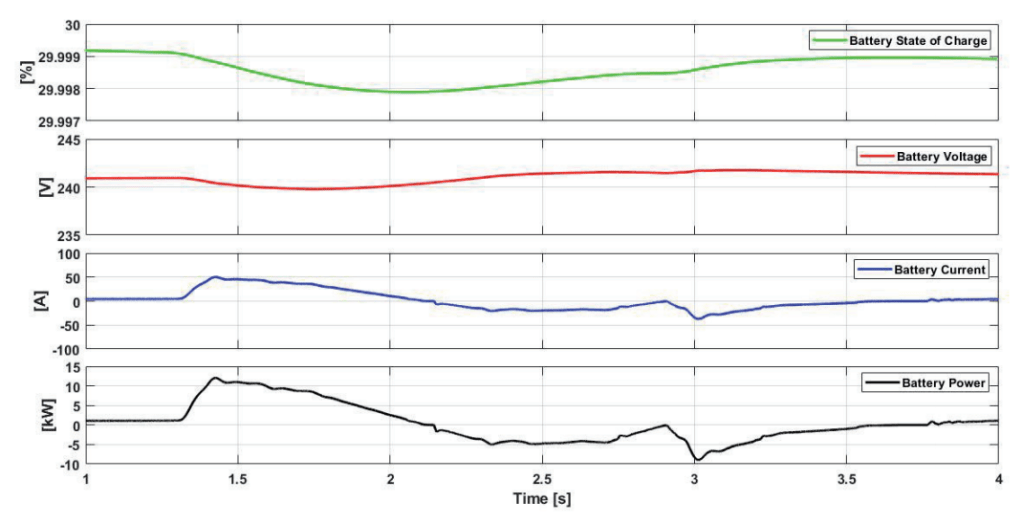
The test microgrid shown in Fig.4 is run for 4s and various characteristics are obtained. The Fig.8, presents the characteristics at the output of PV module, the variation in PV array current, voltage and power with respect to variation in irradiance, respectively. Initially at t=1s, the irradiance is set to 0KW/m2, hence the current, voltage and power are found to be 0.
At t= 1.5s, irradiance starts increasing, PV array current and PV power follows the same pattern as that of irradiance and hence, starts increasing. At t=2.5s, irradiance is highest and hence, the PV array current and the corresponding PV array power reaches their highest value with respect to the irradiance pattern. Irradiance values decreases after t=2.5s, which is followed by PV array current and PV array power, while the PV array voltage is found to be almost constant at the output of PV module. The output of the battery module is shown in 9, depicts the state of charge (SOC), voltage, current and power of the battery, respectively. Initially at t=1s, battery current and power are zero, so a constant voltage is maintained while the SOC of battery is 29.999 percent. Now, at t=1.3s, load is switched on while PV power is zero, battery starts feeding the load. So, the battery current and power starts increasing while its state of charge and voltage starts decreasing. At t=2s, PV generates power almost equal to the load power, so there is no need for the battery to serve the load. Hence, the battery current and power becomes zero while the SOC and voltage of battery becomes constant. Now, after 2.1s, the excess amount of power generated by PV is used to charge the battery, hence the battery current and power increases in the negative direction (showing charging of battery) while SOC of the battery starts increasing and voltage is maintained at the initial voltage level. Again, at t=2.9s, the load is switched off, the battery gets more power to get charged which is shown by further increase in the battery current and power in the negative direction and the SOC of the battery in positive direction while the battery voltage is maintained at a constant value. Now when the PV power becomes zero, battery current and power are brought back to zero while SOC of the battery and its voltage are constant.
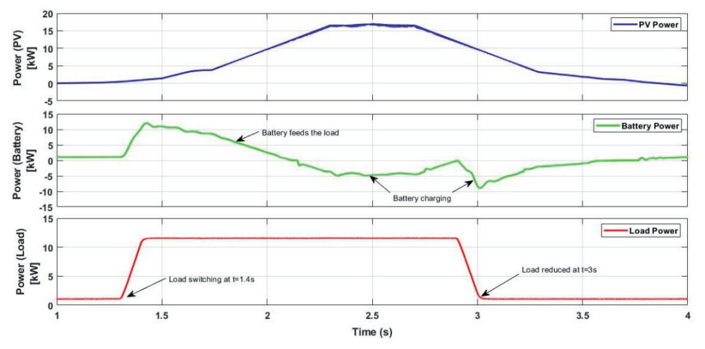
The PV generated power for various irradiance values, the corresponding response of the battery and load power is shown in Fig.10. At t=1s, the total load is fed by the battery as there is no generation by the PV module. At t=1.4s, load switching is done and load power is increased. The battery starts delivering more power to the load, while PV also starts generating power. Battery continues to feed the load along with the PV till the generated PV power becomes equal to the required load power. At t=2.2s, battery stops feeding the load, rather it starts charging by the excess amount of power generated by the PV. At t=2.7s PV power starts decreasing, so battery starts feeding the load. At t=2.9s, PV is capable of generating the power required by the load and starts charging the battery with the excess amount of power generated. At t=3s the load is switched to 0, the battery continues to get charged till the PV stops generating power. Thus the battery supports the PV generation by discharging and charges itself when the generation is in excess. The energy management works well for standalone mode of operation.

0.2 Grid Connected Mode of Operation
Fig.11 shows the result of a 60kW power station. Fig.11a shows the power generated by the PV during a day and the power to be used on site for local purpose. Fig.11b shows the local load power demand. Thus, PV generation minus the local load demand gives the surplus PV power which may be supplied to grid. The operator bids the power to be supplied to grid as shown in Fig.11c with a blue curve. Thus the difference in bid power and PV generated power may find as shown in Fig.11d.
The proposed BESS energy management works on the concept that a total 20kW PV generated power will be utilised for local onsite purpose rest is sent to grid. This means that PV power feeds the local local and whatever the deficit power is, it will be fed by BESS. In case, PV power is available and load is less than 20kW, whatever power is available after feeding load is utilised for charging the BESS. Fig.11e shows that the BESS feeds the load during non-availability of PV power, however it also feeds the grid if the bid power is more than PV generation. In case of availability of PV power after feeding local load, the BESS is being charged by the PV power.
0.3 PV Power Smoothing
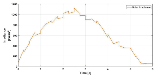
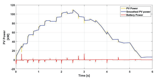
The BESS may also play an important role in grid connected mode of operation, which is smoothing of output PV power by balancing the sharp variation in the PV generation. The solar generation is fluctuating or intermittent in nature and may vary with respect to change in the irradiance pattern. A moving average filter is employed for power smoothing purpose and to obtain the power value which must be supported by the BESS. Fig.12 shows the irradiance pattern received the solar module. The respective smoothing of power is done using BESS as shown in Fig.13.
Conclusion
A new approach is proposed and successfully implemented for improving the availability of the power to consumer by using BESS during the period of intermittency of solar power. The BESS supports the grid during intermittency by an amount of power, which has been promised by the operator. The paper successfully implements an hybrid AC/DC test microgrid, which has the capability of working in grid connected as well as in grid connected mode. The power management algorithm is so designed that BESS has utilization in both the modes of operation. Various test scenario have been successfully implemented and it is shown that the proposed algorithm works well in both the modes of operations.
REFERENCES
[1] Jones, Lawrence E.: Renewable energy integration: practical management of variability, uncertainty, and flexibility in power grids, Academic Press, 2017.
[2] IEEE standard for interconnecting distributed resources with electric power systems, IEEE Std 1547-2003, pp. 1-28, July, 2003.
[3] Juan Manuel Carrasco, Leopoldo Garcia Franquelo, Jan T. Bialasiewicz, Eduardo Galvan, Ram6n C. Portillo Guisado, Ma. Angeles Martin Prats, Jose Ignacio Leon, and Narciso MorenoAlfonso : Power-Electronic Systems for the Grid Integration of Renewable Energy Sources: A Survey IEEE Transactions on Industrial Electronics, vol. 53, no. 4, pp. 1002 -1017, August 2006.
[4] Luthra, Sunil, Sanjay Kumar, Dixit Garg, and Abid Haleem.: Barriers to renewable/sustainable energy technologies adoption: Indian perspective Renewable and Sustainable Energy Reviews 41, pp. 762-776, 2015
[5] Ritu Kandari, Pankaj Gupta, and Ashwani Kumar: Battery state of charge based improved adaptive droop control for power management of a microgrid having large scale renewable generation Sustainable Energy Technologies and Assessments 57,pp.103146, 2023.
[6] Shen Xinwei, Zhu Shouzhen, Zheng Jinghong, et al: Active distribution network planning with distributed generation and energy storage coordination Power System Technology, 2015.
[7] Ju Ping, Huang Ye, Qin Chuan, et al.: Research on Modeling for smart grid in power system Power System and Its Automation, vol.36, no.11, pp.1-6, 2012.
[8] Eyer, J. and G. Corey.: Energy Storage for the Electricity Grid: Benefits and Market Potential Assessment Guide S. REPORT, Editor. Sandia National Laboratories Albuquerque, New Mexico 87185 and Livermore, California 94550, pp. 1-232, 2010.
[9] K. Yoshimoto, N. Toshiya, G. Koshimizu, and Y. Uchida,: New control method for regulating State-of-Charge of a battery in hybrid wind power/battery energy storage system, Proceedings of the IEEE PES Power Systems Conference and Exposition (PSCE ’06), pp.1244–1251, Atlanta, Ga, USA, November, 2006.
[10] Maghraby HAM, Shwehdi MH, Al-Bassam GK.: Probabilistic assessment of photovoltaic (PV) generation systems, IEEE Transanctions on Power System, 17(1) : pp. 205– 208, 2002.
[11] H. Hanl, T.K.A. Brekkenl, A von Jouannel, ABistrika, A.Yokochi: In-Lab Research Grid for Optimization and Control of Wind and Energy Storage Systems, 49th IEEE Conference on Decision and Control Hilton Atlanta Hotel, Atlanta, GA, USA, December 15-17, 2010.
[12] A Etxeberria, Vechiu, A Etxeberria, JM. Vinassa,H.Camblong: Hybrid Energy Storage Systems for Renewable Energy Sources Integration in Micro-grids: A Review, International Power Electronics Conference (IPEC), pp. 532-537,2010.
[13] P. Denholm, E. Ela, B. Kirby, M. Milligan: The Role of Energy Storage with Renewable Electricity Generation, U.S. National Renewable Energy Laboratory Technical Report NREL/TP6A2- 47187, Report, 2010.
[14] Chen, H., et al.: Progress in electrical energy storage system: A critical review, Progress in Natural Science, 19(3): pp. 291-312, 2009.
[15] Alamri, B.R. and A.R. Alamri: Technical review of energy storage technologies when integrated with intermittent renewable energy, Sustainable Power Generation and Supply, 2009. SUPERGEN ’09. International Conference on. 2009.
[16] Martín, J.I.S., et al.: Energy Storage Technologies for Electric Applications in International Conference on Renewable Energies and Power Quality (ICREPQ’11), 2011.
[17] Ibrahim, H., A. Ilinca, and J. Perron: Energy storage systems – Characteristics and comparisons. Renewable and Sustainable Energy Reviews,12(5): pp. 1221-1250, 2008.
[18] Farhangi, Hassan.: The path of the smart grid. IEEE power and energy magazine, 8, no. 1 (2010).
[19] Díaz, González, F., et al.: A review of energy storage technologies for wind power applications, Renewable and Sustainable Energy Reviews, 2012. 16(4): pp. 2154-2171.
[20] Akinyele, D.O. and R.K. Rayudu: Review of energy storage technologies for sustainable power networks, Sustainable Energy Technologies and Assessments, 2014. 8: pp. 74-91.
[21] Cong Jing, Song Kun, Lu Haiwei, Gao Xiaofeng, Xiao Bai.: Review of energy storage technology for new energy power system renewable energy power system, in Advanced Technology of Electrical Engineering and Energy, vol.33, no.3, pp.53-59, March, 2014.
[22] Neeraj , Pankaj Gupta, Anuradha Tomar.: Industry 4.0 Based Efficient Energy Management in Microgrid, Journal of Scientific and Industrial Research, vol. 82, no. 02, 2023.
Source & Publisher Item Identifier: PRZEGL ˛ AD ELEKTROTECHNICZNY, ISSN 0033-2097, R. 99 NR 11/2023. doi::10.15199/48.2023.11.15
