Published by 1. Waldemar ZIOMEK, 2. Krishnamurthy VIJAYAN, PTI Transformers LP, Winnipeg, MB, Canada ORCID: 1. 0000-0002-1216-6513
Abstract. The renewable energy collector transformer (RCT) in a solar station, or a wind farm, transforms the voltage from the collector system to the transmission level voltages. As the primary goal is stepping up the voltage, the RCT is similar in this function to a generator step-up (GSU) transformer, but there are design features and operational characteristics, which would make these units unique, such as typical winding configuration wye-wye-buried delta, the LV winding is typically grounded through the neutral grounding reactor. The design has to include a presence of harmonics in LV currents and voltages.
Streszczenie. Transformator główny stacji energii odnawialnej w stacji fotowoltaicznej lub farmie wiatrowej (stacji OZE) przekształca napięcie z układu zbiorczego na napięcia poziomu przesyłu. Ponieważ głównym celem jest podniesienie napięcia, RCT jest podobny w tej funkcji do transformatora GSU, ale istnieją cechy konstrukcyjne i właściwości operacyjne, które czynią te jednostki wyjątkowymi, takie jak typowa konfiguracja uzwojeń trójkąt – gwiazda-gwiazda, uzwojenie nn jest zazwyczaj uziemione poprzez neutralny dławik uziemiający. Konstrukcja musi uwzględniać obecność harmonicznych w prądach i napięciach nn. (Transformatory główne w stacjach OZE)
Keywords: power transformers, renewable energy station, overvoltage, harmonics.
Słowa kluczowe: transformatory mocy, stacja OZE, przepięcia, harmoniczne
Introduction
The renewable energy collector transformer (RCT), is a specialized power transformer which in a solar station or a wind farm, transforms the voltage from the station collector system, typically 34.5 kV, to the transmission voltage levels, typically ranging from 138 up to 345 kV or 500 kV. The location of RCT in a renewable energy station is shown in Figure 1. While the low-power transformers directly connected to the inverters are well described in the papers and standards [1, 2], the collector transformers are not well described in published references or standards. Therefore, the goal of this paper has been to fill in this gap.
Most of renewable energy stations might use more than one collector transformer for different reasons, such as to limit their physical size, especially for transportation or due to site limitations, or utilize the features of a station design philosophy, such as distributing the loads, or transferring the loads between the sections of the station during faults, or emergency loading.
As the primary goal of an RCT is stepping up the voltage, the transformer is similar in this function to a generator step-up (GSU) transformer. However, there are numerous features and characteristics differentiating RCTs from GSUs, including: (i) typical winding configuration is wye-wye-buried delta, while GSU windings are connected wye-delta, (ii) the LV winding of RCT is typically grounded through the neutral grounding reactor (NGR), while HV is solidly grounded – the presence of NGR may impact the surge transfer from HV to LV side, sustaining the voltage oscillations [3], (iii) the RCT design has to include impact of a presence of harmonics in LV currents and voltages [4], (iv) these units are equipped with on-load tap changer (LTCs), located on LV side up to 100 MVA and on HV side for higher power ratings, (v) sizing of the unit MVA rating may be optimized, e.g. due to lack of electric power generation at night in a solar station, (vi) high ambient temperature may require an expanded cooling system to avoid an additional loss of insulation life, (vii) the fault calculations should include a realistic infeed from the LV side.
Emerging application of RCTs is Battery Energy Storage System (BESS) – see Figure 2 and 3. This seems to be a future solution for totally renewable green energy source without any dependence on other conventional source of energy generation [5, 6].

Modern Energy Storage Technologies include following storage methods: (i) pumped hydro-electric – most popular technology, used for decades, (ii) compressed air energy, (iii) flywheel energy, (iv) superconducting magnetic energy, (vi) conventional rechargeable batteries, (vii) flow batteries, typically using redox reaction between two liquids separated by membrane, (vii) supercapacitors, (viii) hydrogen and (ix) thermal energy (see Figure 3) [6].

Selected design features of RCT
Most HV transmission systems are designed to be effectively grounded [7, 13, 14]. To interconnect with such transmission systems, it is usually required that the wind or solar station provide a ground point to the transmission system on an HV side of a transformer. To avoid excessive temporary overvoltages, e.g., in the event of a ground fault on the LV collector system, or the surge transfer form HV side, it is usually necessary that the renewable energy collector transformer also provide a ground point at its LV side. A transformer winding connection that provides a ground point to both the HV and LV terminals is a grounded-wye (HV), grounded-wye (LV) with a delta tertiary (TV). This connection is used for most renewable energy plants in North America. The delta tertiary winding is needed to provide a path for zero-sequence currents and triplen harmonics to circulate, and this tertiary may not be loaded. Same comments refer to the BESS stations. One may note that the wye connected LV winding allows also for easy line-to-ground fault detection on LV side. Moreover, a relatively high LV voltage of 34.5 kV results in a smaller cable size and reduced load loss of the renewable energy station.
Based on a database of several dozens of units built at PTI Transformers LP, the following parameters are typical:
• the top power rating ranges from 50 to 350 MVA,
• the cooling designation is typically ONAN/ONAF/ONAF, with ONAN/ODAF/ODAF for larger power ratings,
• the LV voltage varies between 13.8-34.5 kV, with 34.5 kV in a vast majority of units,
• the HV voltage varies within 100-345 kV, with 230 kV in majority of units,
• majority (90%) of RCTs had a TV winding, most of them at 13.8 kV,
• the HV-LV impedance at base power rating varies from 4% to 15%, averaging at 9%.
Typical winding configuration of an RCT, counting from the core, is TV-LV-HV-LTC (see Figure 4).
Following additional comments can be made: (i) very often an electrostatic shield, a.k.a. core shield, is used on the core leg, (ii) the LTC winding position may change, depending on the transformer impedance and which circuit is regulated, i.e., HV or LV, (iii) the HV lead is typically connected to the axial center of the winding (becoming a center-fed design).
In case when the transformer impedance matching to existing transformer(s) is required, the position of windings can be changed to, e.g., TV-LTC-LV-HV layout.

Operational characteristics of RCT
LV with Neutral Grounding Reactor – transferred surge voltages
The surges caused by lightnings or switching operations, can be transferred within and through the transformer from one winding system to another. The voltages transferred through the transformers are mainly fast-front, or slow-front overvoltages.
The transferred surge has usually both the capacitively and inductively transferred components which are superimposed on the power-frequency voltage. The capacitively transferred component is typically in the MHz range and is seen first in the transferred surge. The inductively transferred component is slower than the capacitive one and is seen later. Its shape and amplitude change in time, because the distribution of the voltage along the primary winding is time-dependent. The magnitude of the transferred voltages depends on the construction of the transformer, damping effect of the winding, capacitances of the transformer, winding turns (transformation), vector group, connection to the network, etc. In addition, the waveshape of the incoming surge has an important role [3, 8-11]. Often neglected factor is a neutral grounding method. Majority of RCTs are grounded through reactance with a purpose is to lower a ground fault current in the 34.5 kV system (typically single-phase underground cables), so that one can minimize the sizes of main conductors, concentric neutral and grounding wires in the collector system – those result in significant cost savings, as wind turbines can be up to 15 km away from a substation. Neutral Grounding Reactor (NGR) is typically easier to install and more durable than a neutral resistor. Typical NGR impedance is between 0.5-3.5 Ω. A presence of NGR in the neutral has impact on the transient response of a transformer. Grounding a transformer directly or with a resistor will result in lower internal overvoltages, than those appearing when an NGR is used. This characteristic – i.e., oscillatory response of a RCT grounded through reactance – was studied many times and typical results were presented at IEEE PES Transformers Committee [12]. The unit in this particular study was a 200 MVA windfarm collector transformer, 34.5Y-345Y kV with buried TV, with 1050/110 kV BIL HV and 200/200 kV BIL LV levels. The unit was analyzed for a transient response with LV neutral point: (i) grounded directly, (ii) grounded through resistance and (iii) grounded with reactance, NGR. The results on Chopped Wave application to LV terminals with different grounding methods are shown in Table 1.
From the results presented in Table1, one may see that while the LV voltage to ground does not change significantly with grounding method, the voltage from TV to ground and to LV is some 35-45% higher when the neutral is reactance grounded.
Table 1. Comparison of transient response (positive and negative magnitude) of LV and TV winding to LV CW of 220 kV, 3.5/50 ms, with different grounding type
Harmonics
The harmonic content is established by measurements of currents and voltages and performing the harmonic spectrum analysis. Next, (i) the UL K-factor, or (ii) IEEE harmonic loss factor FHL can be calculated (see Table 2). Using these factors, the stray loss increase from a fundamental frequency is calculated.
Table 2. Harmonic loss factor FHL (IEEE C57.110 [4]) and K-factor (UL UL1561 and 1562)
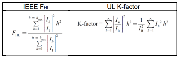
IEEE C57.110-2018 [4] defines harmonic loss factor FHL which is commonly used in HVDC, FACTS, and power applications, while UL1561-defined K-factor is used for distribution transformers connected to electronic equipment. The FHL factor is a function of the harmonic current spectrum and is independent of the relative magnitude. The UL K-factor is dependent on both the magnitude and the distribution of the harmonic current. For a new transformer with harmonic currents specified as per unit of the rated transformer secondary current, the K-factor and FHL factor have the same numerical values. The numerical value of the K-factor equals the numerical value of the harmonic loss factor only when the square root of the sum of the harmonic currents squared equals the rated secondary current of the transformer.
Voltage variation with LTC
Contrary to conventional GSU’s, RCTs are equipped with on-load tap changers (LTCs) to allow for the voltage variation under load. Typical voltage variation is: ±10% in ±8 steps, or ±10% in ±16 steps. Most often the high speed, resistor vacuum type, or high current reactor vacuum type (for LTC in LV circuit) are used. In majority of the RCTs, the LTC is provided on HV side for the HV voltage variation. Although the intention is for HV variation, most transmission voltages (specially rated 230 kV and higher) are very stable. Hence, the LTC is mostly used during initial commissioning to test the reactive performance of the wind or solar farm, by forcing the voltage changes, see e.g. [15].
In very few of the RCT units the LTC is required to vary the LV voltage, and then, depending on availability of LTC and cost consideration: (i) LTC is provided on LV side, or (ii) LTC is provided on HV side for LV variation (i.e., resulting in a variable core flux design).
Optimization of the MVA rating
Both solar and wind stations do not produce the rated power at all times, hence the power rating of a RCT could be accordingly adjusted, reducing size, weight and cost of transformer. However, the maximum power rating is often selected, as most of users want the RCT to match maximum output of the renewable energy station, and in addition the underloaded transformer insulation will last much longer than standard 20 years, meeting a long insulation life expectation of, say, 40-50 years.
Impact of high ambient temperature
Most solar stations are built in the areas of high exposure to the sunlight, having higher ambient temperatures, for momentary, daily and yearly average, different from those specified in standards. These higher ambient temperatures, together with solar irradiation increasing the oil temperature, need to be considered while designing and testing these transformers, resulting in higher winding and oil temperatures, and requiring the expanded cooling equipment.
Fault calculations with infeed from LV side
The power rating of solar or wind stations is constantly increasing, typically in several hundred MW range. The tertiary fault current will depend on infeed from the LV side. Therefore, a realistic infeed from LV side is required, to properly assess the short circuit current levels. The current of 25 kA or 40 kA is the typical system fault level on the LV side, limited by available circuit breakers’ rating.
Reverse Power Flow
In last 10-15 years the reverse power flow, resulting from the energy delivery by distributed energy sources, is affecting more and more transformers, especially these originally designed for a defined power flow direction (step-up, or step-down operation).
The operation of a transformer under reversed power flow needs to be evaluated for: tap changer’s range, voltage regulation, core overfluxing (higher core loss and temperature), load losses, etc. – see Fig.5.
This situation is especially complex for the dual LV units, supplying or receiving the power from different LV busses.
Examples of RCTs design
The RCT unit, for wind, solar and BESS applications are characterized with expanded cooling system, HV-LV-TV bushing arrangements and employment of LTCs (Figure 6). The oil preservation system for these large power transformers is based on the oil expansion vessel with separation of the oil and air with the air bag and the breather.

Recently a trend of power ratings going up to 400 MVA range is emerging. With the limitation on the LV breaker capacity, dual LV units are being considered for larger units. There is also requirement of 500 kV class renewable energy units from some customers. The number of transformer deliveries for BESS application is steadily increasing. Some customers are also looking for flexibility of HV voltage, so that it can be used in two different systems, e.g., reconnectable units of 230 x 115 kV, or 345 x 230 kV voltage (see Figure 7, more details in [17]). In the nameplate one may see that the corner of a delta connected TV winding is brought out and grounded. If required, a winding insulation test or an applied voltage test can be performed. In the field, one may measure the TV winding insulation resistance, to verify there are no shorts to ground. If there were two corners brought out, the user can operate the transformer with open or closed delta TV [16]. The above aspects increase the complexity of designs and experience of transformer suppliers plays an important role in such cases.

Conclusions
• With continuous development of large solar and wind distributed energy resources, the application of the renewable energy collector transformers (RCT’s) is increasing, with power rating up to 400 MVA, the voltage class up to 500kV.
• These units are equipped with LTCs, typically on HV side.
• The HV and LV windings are wye-connected and grounded, with buried delta TV windings.
• LV winding neutral point is typically grounded with a reactor, hence increasing the electric stresses within and between the windings due to the voltage transients produced by lightning or switching impulses, or system faults.
• Presence of inverters in the renewable energy stations introduces the voltage and current harmonics, which need to be considered for the RCT design, resulting in higher load losses and typically leading to expanded cooling system.
• Often higher ambient temperatures and solar irradiation also lead to expanded cooling system design.
REFERENCES
[1] IEEE Std C57.159-2016 IEEE Guide on Transformers for Application in Distributed Photovoltaic (DPV) Power Generation Systems
[2] IEC/IEEE 60076-16:2018 Power transformers – Part 16: Transformers for wind turbine applications
[3] IEEE Std C57.142 – IEEE Draft Guide for to Describe the Occurrence and Mitigation of Switching Transients Induced by Transformers, Switching Device, and System Interaction
[4] IEEE Std C57.110-2018 IEEE Recommended Practice for Establishing Liquid Immersed and Dry-Type Power and Distribution Transformer Capability when Supplying Nonsinusoidal Load Currents
[5] Zhang Z., Mode for reducing wind curtailment based on battery transportation, J. Mod. Power Syst. Clean Energy, 2018
[6] Refaat S.S., Ellabban O., Bayhan S., Abu-Rub H., Blaabjerg F., Begovic M.M, Smart Grid and Enabling Technologies, First Edition, John Wiley & Sons Ltd, 2021
[7] Ackermann T., (editor) Wind Power in Power Systems, Second Edition, John Wiley & Sons Ltd, 2012
[8] IEC 60072-2: Insulation coordination, Part 2 Application Guide
[9] IEEE Std 142 Recommended Practice for Grounding of Industrial and Commercial Power Systems, 1991 (revised in 2007)
[10] Tian C, et al, Lightning Transient Characteristics of a 500 kV Substation Grounding Grid, 7th Asia Pacific International Conference on Lightning, November 1 4, 2011, Chengdu, China
[11] Saied M., Effect of Transformer Sizes and Neutral Treatments on the Electromagnetic Transients in Transformer Substations, IEEE Trans. On Industry Appl., VOL. 31, NO. 2, Mar-Apr 1995
[12]https://grouper.ieee.org/groups/transformers/subcommittees/performance/C57.142/F17ImpactOfDifferentNeutralGroundingMethods-Ziomek.pdf
[13] IEEE Std C57.12.00-2021, IEEE Standard for General Requirements for Liquid-Immersed Distribution, Power, and Regulating Transformers, 2021
[14] CSA Std C88-16, Power transformers and reactors, 2016
[15] WECC Generating Facility, Testing and Model Validation Requirements, 2020
[16] IEEE Std C57.158-2017 – IEEE Guide for the Application of Tertiary and Stabilizing Windings in Power Transformers
[17] Ziomek W., Vijayan K., Ho A., Design and Operation of Renewable Energy Collector Transformers, 2023 CIGRE Canada Conference & Exhibition, Vancouver, BC, Sept.25 –28, 2023
Authors: Dr. Waldemar Ziomek, P.Eng., PTI Transformers LP, Winnipeg, MB, Canada, e-mail: wziomek@ptitransformers.com; Kroshnamurthy Vijayan, MSc, PTI Transformers LP, Winnipeg, MB, Canada
Source & Publisher Item Identifier: PRZEGLĄD ELEKTROTECHNICZNY, ISSN 0033-2097, R. 100 NR 11/2024. doi:10.15199/48.2024.11.39
