Published by 1. Marwan R. Abed, 2. Oday A. Ahmed, 3. Ghassan A. Bilal, University of Technology Iraq, Baghdad, ORCID: 1. 0000-0002-1257-2810; 2. 0000-0001-7214-3412; 3. 0000-0002-5090-103X
Abstract. When implementing a DC distribution network, it is much easier to integrate distributed energy sources than it is with an ac grid. Furthermore, the efficiency and reliability of DC distribution networks outperform those of AC systems. The protection of the DC distribution networks, particularly the interruption and isolation of short-circuit fault currents, is still a major problem. Traditional mechanical and hybrid circuitbreakers for DC fault protection have the disadvantage of being sluggish to operate, necessitating the use of high-power equipment. The Solid-State Circuit Breaker is the best choice for quick fault interruption. Since they employ thyristors, Impedance-Source Circuit Breakers are among those that provide automated fault detection and clearing. In this work, a new DC circuit breaker based Δ-impedance source configuration is proposed for medium and low voltage DC distribution networks to provide the bidirectional operation which has also become the general requirement for the modern power system. The proposed topology uses three-coupled windings with one capacitor and four SCR thyristors to facilitate the bidirectional operation. MATLAB/Simulink environment is used to analyze and evaluate the performance of the proposed DC circuit breaker to protect the 240V DC microgrid configuration with different fault conditions and locations. The results obtained prove that the proposed DC circuit breaker has a good performance in protecting the DC distribution networks.
Streszczenie. Wdrażając sieć dystrybucyjną prądu stałego, znacznie łatwiej jest zintegrować rozproszone źródła energii niż z siecią prądu przemiennego. Ponadto wydajność i niezawodność sieci dystrybucyjnych prądu stałego przewyższa sieci prądu przemiennego. Ochrona sieci dystrybucyjnych prądu stałego, w szczególności przerywanie i izolowanie prądów zwarciowych, nadal stanowi poważny problem. Tradycyjne mechaniczne i hybrydowe wyłączniki automatyczne do ochrony przed zwarciami prądu stałego mają tę wadę, że działają wolno, co wymaga użycia sprzętu o dużej mocy. Wyłącznik półprzewodnikowy to najlepszy wybór do szybkiego przerywania zwarć. Ponieważ wykorzystują tyrystory, wyłączniki źródła impedancji należą do tych, które zapewniają automatyczne wykrywanie i usuwanie usterek. W tej pracy zaproponowano nową konfigurację źródła Δ-impedancji opartą na wyłączniku prądu stałego dla sieci dystrybucyjnych prądu stałego średniego i niskiego napięcia, aby zapewnić dwukierunkową pracę, która stała się również ogólnym wymogiem dla nowoczesnego systemu elektroenergetycznego. Proponowana topologia wykorzystuje trzy sprzężone uzwojenia z jednym kondensatorem i czterema tyrystorami SCR, aby ułatwić pracę dwukierunkową. Środowisko MATLAB/Simulink jest wykorzystywane do analizy i oceny wydajności proponowanego wyłącznika prądu stałego w celu ochrony konfiguracji mikrosieci 240 V DC z różnymi warunkami i lokalizacjami uszkodzeń. Uzyskane wyniki dowodzą, że proponowany wyłącznik prądu stałego ma dobrą skuteczność w zabezpieczaniu sieci dystrybucyjnych prądu stałego. (Zabezpieczenie mikrosieci DC za pomocą ΔCB)
Keywords: DC microgrid protection; Coupled inductor; DC circuit breaker; Bidirectional operation; Impedance source circuit breaker
Słowa kluczowe: ochrona mikrosieci prądu stałego; cewka sprzężona; wyłącznik prądu stałego; Działanie dwukierunkowe
Introduction
The twentieth century began with a critical discussion over the form of energy supply and its essential elements. When Nikola Tesla with George Westinghouse argued for Alternating Current (AC) while Thomas Edison argued for Direct Current (DC). It was evident that the generation of DC power was restricted to a low voltage, and the voltage drop was a key concern. As a result, Edison’s power plants had to be used locally, which meant that loads had to be near the generating stations. The success of this fundamental milestone in the history of electricity notably ushered in the era of central power generation (power plants) and the global spread of AC transmission and distribution systems. In addition, power plants fuelled by fossil fuels (gas and coal) have risen to prominence as a source of electricity. To this time, AC power systems have lasted for even more than a century, and AC loads have ruled the market. However, high energy prices, as well as a lack of funds to build new big power stations with long-distance transmission networks, are some of the limitations to meet rising energy demand. Furthermore, ageing power system infrastructures, global warming, increased awareness of restricted power generation resources, higher power consumption requirements, and growth in the use of DC loads due to improvements in power electronics all indicate that transformation of the existing energy system is unavoidable [1, 2].
DC sources have been subjected to many developments causing an increment in the efficiency and live time of these sources, also the use of various DC loads, and the use of energy storage devices have led the way to use the of DC microgrids (DC MG). Harmonic, Ferranti, and skin effects are essentially non-existent in the DC-MG. As a consequence, DC MG will be better suited for new power systems than AC MG. The DC-MG idea may be viewed as a master foundation for using Smart Grid (SG) technologies [3]. The main problem in these DC MG is that the zerocrossing point is not present, so modern protection devices are needed to limit and interrupt the high fault current rapidly without producing sparks [4, 5].
The traditional mechanical DCCBs have many disadvantages such as Low current interruption abilities, slow response time, and low durability [5, 6], so a faster solid-state DCCBs have been suggested, these breakers provide a higher reliability and longer lifetime. The main disadvantage of such types of DCCBs are the demand for an additional forced commutation and sensing elements, which cause an increase in the circuit complexity and cost and also the high on-resistance (Ro) of the semiconductor switches [4-9].
The Impedance source DCCB is suggested as a faster response that isolates faults in microseconds and has an automatic turn-off because of its natural commutation principle [5, 10, 11].
In [11] produced the first unidirectional impedance source DCCB, consisting of one thyristor (SCR) and two capacitors and inductors which had been arranged as a cross shape. The absence of a common ground in the cross DCCB is solved by introducing the series ZCB in [10, 12]. Other research is done to reduce the reflecting current to zero and reduce the size and response time using coupled inductors in DCCBs as in [13]. In [14, 15] producing a symmetrical bidirectional ZCB with coupled-inductors. In [16, 17], a unidirectional Gamma DCCB (ГCB) was present. Also, in [18-22] presented the T-shape DCCBs (TCB). In [23-25] introduced a Y-shape DCCB (YCB), which consisted of a single capacitor and three coupled-inductors. The most important advantage of this configuration is the higher reflected current gain which produced by the secondary windings, as well as the three inductors’ turn ratios.
In this paper, a new symmetrical bi-directional with delta-shape coupled-inductors (ΔCB) is used in the protection of a DC MG, the following sections will introduce the new circuit breaker and test the protection of a 240V DC MG.
Configuration of the suggested ΔCB
A new circuit breaker with three coupled inductors configuration, in which the inductors are connected in a delta shape, is introduced as a new impedance source CB. It also consists of a single capacitor and four SCRs arranged in two back-to-back switch pairs, as shown in Fig.1. The direction of power flow in the ΔCB is selected by the two switches in the gate circuit S1 and S2 as shown in Table.1.
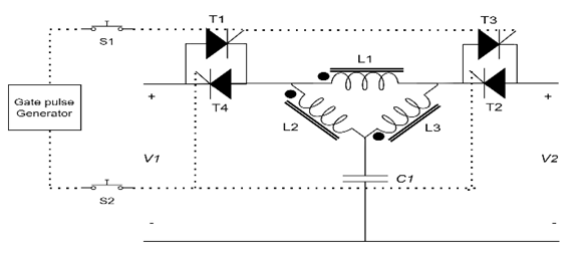
Table.1. Switches states of Gate circuit

Table.2. The values of the parameters of the proposed ΔCB

Operation principle of the ΔCB
During steady state, the power flows from V1 to V2 through T1, L1, L2, L3, and T3, as shown in Fig.2. While the power flows from V2 to V1 through T4, L1, L2, L3, and T2 during opposite power flow direction, as illustrated in Fig.3. In the event of a transient situation, such as a short circuit fault or under sudden load change, the capacitor will act as the source that fed the transient current through the three delta-coupled inductors.


As shown in Fig.4, these inductors also act as a channel for the reflected current. If this reverse current is equal to a certain value of the forward current, it will force the thyristors to turn off immediately, causing an interruption to the source current.
Input-to-output current response
By driving the current transfer relation of the ΔCB from the three loop equations, So the input-to-output current relation is shown in Eq.(1):
I1/I2=−𝑠(𝐿3−𝑀13+𝑀23)(𝐿3−𝑀31+𝑀32)+(𝐿1+𝐿2+𝐿3−𝑀12−𝑀13−𝑀21+𝑀23−𝑀31+𝑀32)(𝑠𝐿3+𝑅𝐿+𝑍𝑐)𝑠(𝐿2−𝑀12+𝑀32)(𝐿3−𝑀31+𝑀32)−(𝐿1+𝐿2+𝐿3−𝑀12−𝑀13−𝑀21+𝑀23−𝑀31+𝑀32)(𝑠𝑀32−𝑍𝑐)………Eq.(1)
Where: Zc: The total impedance of the capacitor By using the parameters in Table.2 to plot the bode plot of this relation, as shown in Fig.5:
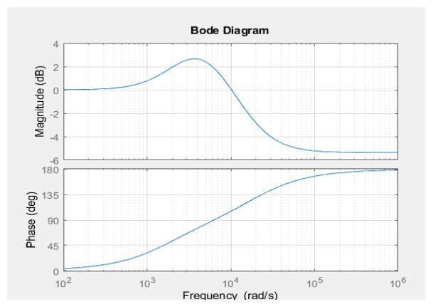
The figure shows a negative amplitude and higher value than the amplitude in low frequencies (steady state) with 180⁰ in phase. This reverse current will cause in a decrement in the first thyristor current making it lower than latching current, so the thyristor will turn-off causing in an interruption in the circuit breaker.
Simulation Results
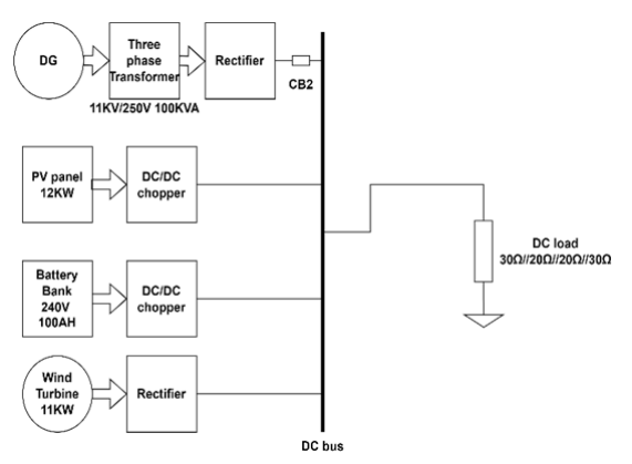
The ΔCB should be used to protect a DC microgrid (DCMG) from a short circuit fault. A MATLAB tool is used in this test. The simulation type is discrete of 5µs sampling time. A hybrid power supply system is constructed from three power sources: a connected AC grid, wind energy, and solar panels. The battery bank is 24v and used for transient cases during the changing from source to source and in an emergency. Every single source of the three power sources is regulated by a controller in order to provide a continuous supply to the load [26]. The sequence of the power source work in this simulation:
1. AC grid: From 0s to 1.5s.
2. Solar panel: From 1.5s to 3s.
3. Wind turbine: From 3s to 4s.
The schematic diagram of the used DCMG is shown in Fig.6. The bus voltage of the DCMG is 250V and the load consists of four parallel loads 30Ω, 20Ω, 20Ω, and 30Ω (the total load is equal to 6Ω), the load is connected to the DC bus.

Check the System Protection Under Fault in Parallel to Load
a) The CB is in series with the load
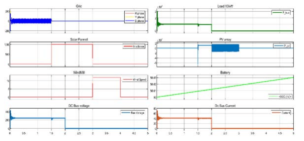
The system is tested under normal operation and records the voltage and current of each power source, bus voltage, and load current (Ibus=ILoad). The simulation time is 5s. The steady-state results are obtained Fig.7.

Three different fault cases will be tested, as follows:
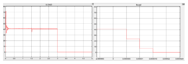
The first fault case: By inserting the fault after one second from a run during the period of the AC grid supply source, The AC is converted to DC through the rectifier and the inductive filter, and the load current shows the isolation of the breaker in about 10µs as shown in Fig.8 (Ibus=ILoad), and the other results are obtained as shown in Fig.9.
The second case: By inserting the fault after two seconds from the simulation run during the PV panel (solar panel) supply source period, Also, the load current shows the isolation of the breaker in about 10µs as shown in Fig.10, and the results are obtained as shown in Fig.11.


The third case: By inserting the fault after three seconds from a run during the period of the wind turbine and its rectifier as a supply source, the load current shows the isolation of the breaker in about 10µs as shown in Fig.12, and the results are obtained as shown in Fig.13.
b) The CB is in series with the rectifier of the AC Grid
The ΔCB is connected in series with the filter of the AC grid, as shown in Fig.14. The fault occurs after 0.5 seconds, and the source current of the ΔCB interrupted after 4.1ms with an overshoot during transient, as shown in Fig.15. The delay in isolation time and the increment in the current overshoot are because of the ripple in the rectified power and the effect of the inductor used as a filter.

Adding a capacitor in parallel with the input of this ΔCB of 220µF will illuminate the overshoot problem, and the isolation time will be reduced to 35µs, as shown in Fig.16.


Conclusion
MATLAB/Simulink environment is used to analyze and evaluate the performance of the proposed DC circuit breaker to protect the 240V DC microgrid configuration with different fault conditions and locations. The results prove that the proposed DC circuit breaker is well at protecting the DC distribution networks. It shows a faster isolation time of 10µs and no negative part in the source current. That makes it the better choice for protecting DC microgrids. Finally, the result shows that ΔCB could distinguish between fault and step load change.
REFERENCES
[1] D. Kumar, F. Zare, and A. Ghosh, “DC microgrid technology: system architectures, AC grid interfaces, grounding schemes, power quality, communication networks, applications, and standardizations aspects,” Ieee Access, vol. 5, pp. 12230-12256, 2017.
[2] J. J. Justo, F. Mwasilu, J. Lee, and J.-W. Jung, “AC-microgrids versus DC-microgrids with distributed energy resources: A review,” Renewable and sustainable energy reviews, vol. 24, pp. 387-405, 2013.
[3] K. Nandini, N. Jayalakshmi, and V. K. Jadoun, “An overview of DC Microgrid with DC distribution system for DC loads,” Materials Today: Proceedings, 2021.
[4] W. Li, Y. Wang, X. Wu, and X. Zhang, “A novel solid-state circuit breaker for on-board DC microgrid system,” IEEE Transactions on Industrial Electronics, vol. 66, no. 7, pp. 5715-5723, 2018.
[5] S. S. Lumen, R. Kannan, and N. Z. Yahaya, “DC Circuit Breaker: A Comprehensive Review of Solid State Topologies,” in 2020 IEEE International Conference on Power and Energy (PECon), 2020: IEEE, pp. 1-6.
[6] S. Bhatta, R. Fu, and Y. Zhang, “A New Design of Z-Source Capacitors to Ensure SCR’s Turn-Off for the Practical Applications of ZCBs in Realistic DC Network Protection,” IEEE Transactions on Power Electronics, vol. 36, no. 9, pp. 10089-10096, 2021.
[7] S. Bhatta, “Specification, Control, and Applications of Z-Source Circuit Breakers for the Protection of DC Power Networks,” 2021.
[8] V. Raghavendra, S. N. Banavath, and S. Thamballa, “Modified z-source dc circuit breaker with enhanced performance during commissioning and reclosing,” IEEE Transactions on Power Electronics, vol. 37, no. 1, pp. 910-919, 2021.
[9] L. L. Qi, A. Antoniazzi, L. Raciti, and D. Leoni, “Design of solidstate circuit breaker-based protection for DC shipboard power systems,” IEEE Journal of Emerging and Selected Topics in Power Electronics, vol. 5, no. 1, pp. 260-268, 2016.
[10] A. H. Chang, B. R. Sennett, A.-T. Avestruz, S. B. Leeb, and J. L. Kirtley, “Analysis and design of DC system protection using Z-source circuit breaker,” IEEE Transactions on Power Electronics, vol. 31, no. 2, pp. 1036-1049, 2015.
[11] K. A. Corzine and R. W. Ashton, “A new Z-source DC circuit breaker,” IEEE Transactions on Power Electronics, vol. 27, no.6, pp. 2796-2804, 2011.
[12] A. H. Chang, A.-T. Avestruz, S. B. Leeb, and J. L. Kirtley, “Design of dc system protection,” in 2013 IEEE Electric Ship Technologies Symposium (ESTS), 2013: IEEE, pp. 500-508.
[13] A. Maqsood and K. Corzine, “Z-source Dc circuit breakers with coupled inductors,” in 2015 IEEE Energy Conversion Congress and Exposition (ECCE), 2015: IEEE, pp. 1905-1909.
[14] S. G. Savaliya and B. G. Fernandes, “Modified bi-directional Zsource breaker with reclosing and rebreaking capabilities,” in 2018 IEEE Applied Power Electronics Conference and Exposition (APEC), 2018: IEEE, pp. 3497-3504.
[15] S. G. Savaliya and B. G. Fernandes, “Performance Evaluation of a Modified Bidirectional Z-Source Breaker,” IEEE Transactions on Industrial Electronics, vol. 68, no. 8, pp. 7137-7145, 2020.
[16] H. Al-khafaf and J. Asumadu, “Γ-Z-source DC circuit breaker operation with variable coupling coefficient k,” in 2017 IEEE International Conference on Electro Information Technology (EIT), 2017: IEEE, pp. 492-496.
[17] X. Diao, F. Liu, Y. Song, M. X. Y. Zhuang, and X. Zha, “Topology Simplification and Parameter Design of Z/T/CSource Circuit Breakers,” IEEE Journal of Emerging and Selected Topics in Power Electronics, 2021.
[18] C. Li, Z. Nie, H. Li, and Y. Zhang, “A novel solid-state protection scheme for DC system,” in 2016 IEEE 8th International Power Electronics and Motion Control Conference (IPEMC-ECCE Asia), 2016: IEEE, pp. 2039-2042.
[19] Y. Song, Y. Yu, S. Wang, Q. Liu, and X. Li, “A Novel Efficient Bidirectional T-source Circuit Breaker for Low Voltage DC Distribution Network,” in 2021 IEEE 12th International Symposium on Power Electronics for Distributed Generation Systems (PEDG), 2021: IEEE, pp. 1-5.
[20] X. Diao, F. Liu, Y. Song, M. Xu, Y. Zhuang, and X. Zha, “An Integral Fault Location Algorithm Based on a Modified T-source Circuit Breaker for Flexible DC Distribution Networks,” IEEE Transactions on Power Delivery, 2020.
[21] S. Sapkota, K. Pokharel, Y. Wang, W. Li, and H. Wang, “Modified T-Source Circuit Breaker for Bidirectional Operation in MVDC,” in 2020 IEEE Sustainable Power and Energy Conference (iSPEC), 2020: IEEE, pp. 813-818.
[22] X. Diao, F. Liu, Y. Song, M. X. Y. Zhuang, W. Zhu, and X. Zha, “A New Efficient Bidirectional T-source Circuit Breaker for Flexible DC Distribution Networks,” IEEE Journal of Emerging and Selected Topics in Power Electronics, 2020.
[23] H. Al-Khafaf and J. Asumadu, “Bi-directional Y-Source DC Circuit Breaker Design and Analysis Under Different Conditions of Coupling,” in 2018 9th IEEE International Symposium on Power Electronics for Distributed Generation Systems (PEDG), 2018: IEEE, pp. 1-6.
[24] H. Al-khafaf and J. Asumadu, “Efficient Protection Scheme Based on Y-Source Circuit Breaker in Bi-Directional Zones for MVDC Micro-Grids,” Inventions, vol. 6, no. 1, p. 18, 2021.
[25] H. Al-khafaf and J. Asumadu, “Y-source bi-directional dc circuit breaker,” in 2018 International Power Electronics Conference (IPEC-Niigata 2018-ECCE Asia), 2018: IEEE, pp. i-v.
[26] D. SHAH. “DESIGN OF DC MICROGRID.” MathWorks. https://www.mathworks.com/matlabcentral/fileexchange/104120-design-of-dc-microgrid (accessed March 4, 2023).
Source & Publisher Item Identifier: PRZEGLĄD ELEKTROTECHNICZNY, ISSN 0033-2097, R. 99 NR 11/2023. doi:10.15199/48.2023.11.25
