Published by Enaam ALBANNA1, Alya H. AL-RIFAIE2, Ahmed A. Abdullah AL-KARAKCHI3, Northern Technical University (1,2,3) ORCID: 1. 0000-0002-3974-0116; 2. 0000-0002-7978-2193; 3. 0000-0003-1151-3015;
Abstract. High-impedance fault HIF occurs when an energized conductor makes contact with a surface with a high impedance. Conventional overcurrent protection cannot detect this fault due to the low fault current, and there is no effective protection for HIFs. This paper introduces a novel method for detecting HIFs in low voltage distribution systems by decomposing neutral current using Wavelet and FFT. Modeling HIF fault data in Matlab to analyze the proposed scheme. Simulations demonstrate that the proposed method can accurately detect HIF and distinguish it.
Streszczenie. Błąd wysokiej impedancji HIF występuje, gdy przewodnik pod napięciem styka się z powierzchnią o wysokiej impedancji. Konwencjonalne zabezpieczenie nadprądowe nie jest w stanie wykryć tej usterki z powodu niskiego prądu zwarciowego i nie ma skutecznej ochrony dla HIF. W artykule przedstawiono nowatorską metodę wykrywania HIF w systemach dystrybucji niskiego napięcia poprzez dekompozycję prądu neutralnego za pomocą funkcji Wavelet i FFT. Modelowanie danych o błędach HIF w Matlabie w celu analizy proponowanego schematu. Symulacje pokazują, że proponowana metoda może dokładnie wykrywać i rozróżniać HIF. (Wykrywanie uszkodzeń o wysokiej impedancji w niskonapięciowej dystrybucji napowietrznej w oparciu o wskaźniki falkowe i harmoniczne )
Keywords: HIF, Fast Fourier Transform, overcurrent relay, (WT) wavelet transform.
Słowa kluczowe: Szybka Transformata Fouriera FFT, .przekażnik, Transformata falkowa
Introduction
The unconventional flaw High impedance fault HIF is a concern in distribution utility protection because it is difficult to detect. HIFs occur when a primary conductor of a distribution feeder falls and contacts a ground or asphalt surface with a high impedance [1][2]. This surface restricts the current flow below the overcurrent protection level. This type of fault occurs in distribution networks; High Impedance Fault has low current magnitude and transient arcing as main characteristics, depending on contact with a high-impedance surface or object like a tree.
Flow currents with magnitudes less than protective device overcurrent or earth fault pickup current at the feeder substation can cause major environmental or property damage if not extinguished by the feeder protection. A ground fault occurs when a three-phase conductor falls and contacts a high-impedance object or a poorly conducting surface. When HIFs occur in overhead distribution feeders, overcurrent protection devices cannot detect the current fault and provide a trip signal. Because of the faults’ insufficient current draw, which ranges from 0 to 70 amperes depending on the effective touch in the distribution network and is below the overcurrent protection devices’ pickup level. The broken conductors carrying current with objects that are not properly grounded, such as vehicles, trees, and wood fences. This results in the energized conductor touching the ground, posing a public safety risk and negatively impacting power supply reliability. HIFs also arc, posing a fire and electric shock risk.
These factors make finding HIFs in power systems, particularly the distribution network, a common problem [3]. Since 1970, HIFs have been of interest, but detection techniques are still unclear [4][5]. In a conventional fault current, the current amplitude will be more than 10 times the relay pickup, thus the protection relay will respond to the fault. In the case of HIF, the overcurrent relay will not respond because its setting is much higher than the HIF current. [6] presents a lower-order harmonic detection technique from neutral current. Time-frequency analysis based methods [7]. The techniques include the time-frequency algorithm [8], neural network type of feed-forward (multi-layer) method [9], the kalman filter approach [10] and the low order harmonic ratio [11]. Due to their capacity to identify the frequency component of the signal and their position over time, Wavelet transform WT techniques have been widely used in signal processing [12]. These techniques have been used to protect the power system for more than ten years.
WT is a relatively new concept, but it has proven to be a successful method in many application fields such as speech discrimination, optics, acoustics, image processing, and recently in power system application. WT is used in power systems in a variety of fields that have advanced in recent years. The goal of this paper is to detect HIFs on distribution feeders using a new technique for protection based on WT and Fast Fourier Transform FFT. The advantages that the Wavelet Transform and the FFT both offer will be used to the advantage of the proposed protection method.
Modelling of HIF
The modelling of HIFs is needful to understand and study its behavior of this type of fault in an emulation environment. HIFs currents which are related to conditions such as: non-linearity, asymmetry, buildup, intermittence and shoulder. They are also important featured that HIFs have harmonics index for high and low and frequency components respectively [13]. Simulation is necessary because of that recording HIF are not always available due to that in most cases they are difficult to detect by conventional monitoring protection devices. In this study the HIFs are modelled and simulated because of reproduce a conditions that as close as possible to HIF reality. The use of a simulation model should take an electric arc at the fault contact point into account. Arcing has a nonlinear voltagecurrent relationship and may exhibit the behavior of an asymmetric waveform between the negative and positive halves of the cycle. As buildup progresses, this kind of fault current may also show amplitude variations, shoulders, and other characteristics. Based on the model in [14], the HIF model used in this paper, with the main consideration for detection being the voltage V versus I in nonlinearity of the arc. Figure 1 depicts the HIF applied model.
The HIF model is made up of two DC supplies connected in series with two diodes. The current flows through the power supply VP during the positive half cycle and through VN during the negative half cycle. The content of harmonics generated through the fault condition are functions of ( VN – VP ) the difference of voltages and alsothe rate of XL ̸ R. These relations the voltages and X to R were confirmed by simulation tests.

DWT Signal Analysis
HIF current signals are defined as current discontinuities, which means zero crossing regions brought on by the extinguishment and re-ignition of electric arcs. DWT turns into a useful tool for analyzing HIF as a result of its capacity to spot transient and abrupt changes in current signals with time or frequency [15]. For discrete applications, the DWT is:
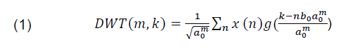
Where: g(:) is the mother wavelet; a and b are the parameters for scale and translation (functions of an integer parameter m); x(n) is the input signal; m is a function of integer parameter

Due to its capacity to extract time and frequency information from a transient input signal [16], WT is an effective algorithm tool for the analysis of transient phenomena. DWT have modelled by utilizing a multistage filtering to the original signal then to the mother wavelet as two types of filter, low pass filter LPF dn (detail) and dual filter of high pass filter HPF an (approximation). The lowpass filter output, dn, is down sampled by two. Scaling the wavelet analysis by two makes the expansion signal in the next step. The term for the component of high frequency high pass filter output provides a detailed representation of the original signal. The approximations an are then signal split to obtain additional information about the original signal. The coefficients of the filter (dn and an) are related to the mother wavelet’s selection. The approximate an and detailed dn versions of the original signal can be obtained in subsequent stages of down sampling by a specific factor referred to as approximation an and detail dn, respectively. Figure 2 depicts the DWT process.
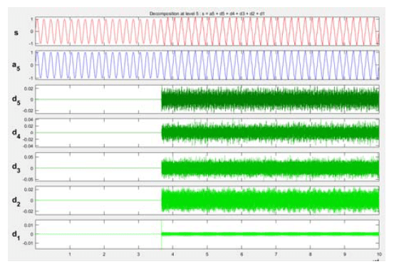
It is possible to implement any type of signal using this efficient technique. The coefficients an and dn of the two filter types (LPF and HPF) are related to the mother wavelet’s parameters. The original signal is then divided into approximation and details, two additional signals that represent a smooth and detailed representation of the signal being processed, respectively. To create the following approximation level (an) and detail level (dn), this analysis is repeated using the approximation that is further decomposed (dn). The process of approximation and level of detail in the DWT are directly proportional to the sampling rate (fn) of the signal being processed [17]. Multi-resolution analysis (MRA) is the method described in [18]. The method provides a signal description for voltages or currents as they vary with respect to various time domain scales, wherein the selection of large scales is associated with lowfrequency signal components and the selection of small scales is associated with high-frequency signal signatures. In addition, the presence of low-order harmonics and highfrequency components distinguishes HIFs currents. Many papers and studies in the field of HIFs have focused on the development of methods that are effective, sensitive, and reliable for detecting these types of faults. As previously described in the literature, these techniques include neural networks, system experts, fuzzy logic control, fast or discrete Fourier transformation, Kalman filtering, and the most recent Wavelet analysis. Despite the fact that wavelet analysis is more complex than other signal analyses, it is suitable for dealing with transient condition (non-stationary) signals, such as those found in HIFs. There are numerous types of mother wavelet, including Coiflet (coif), Daubiches (db), Symmlet (sym), and Harr [19]. Under transient conditions, the selection of the mother wavelet is crucial for detecting and localizing various types of fault [20]. In addition, the selection of the mother wavelet is application dependent. In this proposed work, Daubiches (db) was selected as the mother wavelet type, the neutral current signal was decomposed into five levels for enhanced resolution, and Detail coefficients (d1-d5) were employed for neutral current extraction. d5 detail coefficients are used (wavemenu-matlab) for one dimension 1D.
Fast Fourier Transform
Fast Fourier Transform FFT in power system protection is one of the most well-known signal processing techniques. For digital signal processing DSP applications, discrete Fourier transforms (DFT), can be implemented using FFT algorithms. FFT algorithms based on harmonic analysis provide a precise frequency spectrum with a quick response time. The FFT can indicate HIF current signatures in a unique manner [21]. In addition to this, depending on the frequency resolution, the FFT can also provide interharmonic signals.
Proposed Technique for HIF
In an HIF condition, current will flow across ground identically to a ground fault, with the exception that the amplitude will be low. In order for the protection relay not to detect it, as specified. To detect HIF, neutral line current fault signatures superimposed with HIF are considered. DWT and FFT are used to detect arcing, but DWT analysis is superior for extracting high-frequency current signals. Therefore, the MRA technique of DWT is applied to the neutral line signal to discriminate the HIF signature. This signal is decomposed into multiple levels in order to obtain the desired coefficient d5. Discrete Daubiches (db) is chosen as the mother wavelet for this study, with five decomposition levels. By analyzing the decomposition’s results. FFT is used to analyze the neutral current’s harmonic content, specifically the third harmonic, and d5 is used to determine the fault index for tracking the disturbance period. HIF declares that a trip signal will be generated to disconnect the feeder when two conditions are verified. Figure 3 depicts the flowchart of the proposed method.

Modelling and simulation results
The study system, shown in Figure 4, is a low voltage in distribution feeder network with an 11/440kV distribution transformer and three phases lines (R, S, and T). At this stage, the system is operating normally without HIF. As shown in Figure 5, a temporary fault occurs at t=0.45 second for a duration of 5 seconds, and the circuit breaker responds and trips at t=9.5 seconds. Figure 6 depicts the DWT analysis of the neutral current signal, and the extraction analysis reveals that the value of the detail d5 coefficient relative to the steady-state value of neutral current was 0.02 p.u. From the decomposition signal information d5 detail coefficient, it was determined that the content in d5 (absolute values) shown in Figures 7a and b, respectively, is proportional to the transient disturbances that occur in the neutral line (current signal). The disturbances measured in detail coefficient d5 is continuous between 0.37 seconds when the disturbance occurs and 10 seconds that indicate the end of the HIF cycle. HIF index can be thought of as the energy contained in coefficient d5, these energies can be derived through time integration.


Depending on the disturbance (HIF) in the neutral current, the energy (area under curve) increases or decreases. It can record the d5 proportion of fault events.
The fault event is continuous for HIFs that are sustained. To identify permanent HIFs, the coefficient d5 is used as a fault index. To enhance and increase the validation of the proposed detection, an analysis for harmonics of lower order, including odd harmonics of the order such as the 3rd, 5th, 7th, etc., is added, as well as the computation of the 3rd and 5th harmonics components. As depicted in Figure 8, the waveform of sustain HIF in neutral current is indicative of the odd harmonic type of neutral currents with an order between 3 and 13. The FFT analysis of the neutral current of sustain HIF in Figure 8 is depicted in Figure 9, from which it is possible to observe that the odd harmonic currents of orders 3rd, 5th, and 7th are distinct and have high amplitude. During load switching and network fault occurrence, these low-order harmonics are observed under two circumstances.


Conclusions
The detection of HIFs in low-voltage overhead distribution feeders is crucial because they pose a significant threat to human life. These conventional overcurrent protection schemes cannot detect HIF. In this study, a novel technique for protecting HIFs is proposed. By extruding the detailed coefficients in DWT for the declared fault condition, a new scheme algorithm is created. The detail d5 was used to detect the HIF in this study. Additionally, harmonic analysis was added to enhance the detection capability, and the algorithm was developed in Matlab. The new method demonstrates that the existence of HIF is contingent on two parameters: the absolute value of the d5 coefficient and the presence of the third and fifth harmonics. According to the simulation results, the proposed technique detects the HIF with sufficient accuracy.
REFERENCES
[1] D. P. S. Gomes , Cagil Ozansoy and Anwaar Ulhaq, “High sensitivity vegetation high-impedance fault detection based on signal’s high- frequency contents,” IEEE Transactions on Power Delivery, vol.33, no. 3, pp. 1398 – 1407, 2018.
[2] Alya H. AL-RIFAIE, et al. “Analysis of faults on high voltage direct current HVDC transmissions system”, Przegląd Elektrotechniczny, issue. 2 pp. 49-53, FEB 2022.
[3] Ghaderi, H. L. Ginn Iii, and H. A. Mohammadpour,“High impedance fault detection: A review”, Elect. Power Syst. Res., vol 143,pp. 376-388 ,2017.
[4] S. Gautam and Brahma, “Detection of high impedance fault in power distribution systems using mathematical morphology,”IEEE Transactions on Power Systems, vol. 28, no. 2, pp. 1226–1234, 2013.
[5] ZBER, Sanabel Muhson ALHAJ, et al. “Simulation and Analysis of a VSC-HVDC Transmission System Based on DC Line-Line Fault.”, Przegląd Elektrotechniczny, issue. 8 pp. 69-72, AUG 2022.
[6] K. Sekar, N. K. Mohanty and A. K. Sahoo, ” High impedance fault detection using wavelet transform”, Technologies for Smart-City Energy Security and Power (ICSESP), Bhubaneswar, pp. 1-6, 2018.
[7] S. A. Govar, et al. “Adaptive CWT-based overcurrent protection for smart distribution grids considering CT saturation and highimpedance fault,” IET Generation, Transmission & Distribution, vol. 12, no 6, pp. 1366-1373, 2018.
[8] N. Milioudis, G T. Andreou and D. P. Labridis,“ Detection and Location of High Impedance Faults in Multiconductor Overhead Distribution Lines Using Power Line Communication Devices”, IEEE Transactions on Smart Grid, Vol. 6, no.2, pp. 894 – 902,2015.
[9] O. Chaari, M. Meunier and F.Brouaye: “Wavelets: A new tool for the resonant grounded power distribution systems relaying”, IEEE Transaction son Power System Delivery,Vol.12, No. 1, pp. 1–8, 2018.
[10] Mudathir Funsho Akorede and James Katende,” Wavelet Transform Based Algorithm for High- Impedance Faults Detection in Distribution Feeders”, European Journal of Scientific Research, Vol.41 No.2, pp.237-247, 2010. .
[11] Douglas P. S. Gomesm C. l Ozansoy and A. Ulhaq, “High- Sensitivity Vegetation High-Impedance Fault Detection Based on Signal’s High-Frequency Contents”, IEEE Transactions on Power Delivery, vol. 33,no. 3, pp. 1398 – 1407, 2018
[12] N. Vineeth and P. Sreejaya, “High Impedance Fault detection in Low Voltage Distribution Systems Using Wavelet and Harmonic Fault Indices,” 2020 IEEE International Conference on Power Electronics, Smart Grid and Renewable Energy (PESGRE2020), 2020, pp. 1-6, doi: 10.1109/PESGRE45664.2020.9070573.
[13] T. Sirojan, et al. “High Impedance Fault Detection by Convolutional Deep Neural Network,” 2018 IEEE International Conference on High Voltage Engineering and Application (ICHVE), ATHENS, Greece, 2018, pp. 1-4.
[14] J. -C. Gu, et al. “High Impedance Fault Detection in Overhead Distribution Feeders Using a DSP-Based Feeder Terminal Unit,” in IEEE Transactions on Industry Applications, vol. 57, no. 1, pp. 179-186, Jan.-Feb. 2021, doi: 10.1109/TIA.2020.3029760.
[15] W. C. Santos, et al. “High-Impedance Fault Identification on Distribution Networks,” in IEEE Transactions on Power Delivery, vol. 32, no. 1, pp. 23-32, Feb. 2017, doi: 10.1109/TPWRD.2016.2548942.
[16] M. Moreto and I. Kursancew Khairalla, “A Voltage Based High Impedance Fault Detection Scheme for Distribution Feeders Using Park and Wavelet Transform,” 2018 Power Systems Computation Conference (PSCC), 2018, pp. 1-6, doi: 10.23919/PSCC.2018.8442520. [15] Ghaderi, A., Ginn, H.L.III, Mohammadpour, H.A.: ‘High impedance fault detection: a review’, Electr. Power Syst. Res., 2017, 143, pp. 376–388
[17] M. Y. Suliman and Mahmood T. Alkhayyat, “High impedance fault detection in radial distribution network using discrete wavelet transform technique”, Archives of Electrical Engineering, vol. 70(4), pp. 873 –886 (2021), DOI: 10.1109/TPWRD.2018.2791986.
[18] D. C. Robertson, et al. “Wavelets and Electromagnetic Power System Transient,” IEEE Transaction on PowerDelivery, vol.11, nº 2, pp. 1050-1058, April 1996.
[19] M. F. Akorede, James Katende” Wavelet Transform Based Algorithm for High Impedance Faults Detection in Distribution Feeders”, European Journal of Scientific Research,vol. 41, no 2, pp. 238-248, 2010.
[20] M. Y. Suliman and Mahmood T. Alkhayyat, “Discrimination Between Inrush and Internal Fault Currents in Protection Based Power Transformer using DWT”, International Journal on Electrical Engineering and Informatics, vol. 13(1), 2021, DOI: 10.15676/ijeei.2021.13.1.1
[21] M. Y. Suliman and M. T. Ghazal, “Detection of High impedance Fault in Distribution Network Using Fuzzy Logic Control,” 2019 2nd International Conference on Electrical, Communication, Computer, Power and Control Engineering (ICECCPCE), 2019, pp. 103-108, doi: 10.1109/ICECCPCE46549.2019.203756.
Authors: Enaam ALBANNA2, E-mail: enaam.albanna@ntu.edu.iq; Alya Hamid Al-Rifaie1, E-mail: alya.hamid@ntu.edu.iq; Dr. Ahmed A. Abdullah Al-Karakchi1, E-mail: ahmedalkarakchi@ntu.edu.iq.
Source & Publisher Item Identifier: PRZEGLĄD ELEKTROTECHNICZNY, ISSN 0033-2097, R. 99 NR 7/2023. doi:10.15199/48.2023.07.45
