Published by Jacek KLUCZNIK, Gdansk University of Technology, Faculty of Electrical and Control Engineering. ORCID: 0000-0002-2328-9180
Abstract. The medium voltage underground cable sheaths are usually bonded and earthed in every substation on the cable route. This results in additional power losses in the sheaths. The paper presents an idea of reducing power losses caused by sheaths cross-bonding. The idea of sheaths cross-connecting only in selected MV/LV substations is given instead of a typical solution, where sheaths cross-bonding requires installing additional joints on the cable route. It leads to a significant power losses reduction while investment cost remains low. Two cases are analysed in the paper: a theoretical simple radial network and a part of a real open-loop network. A significant power losses reduction was obtained in both cases
Streszczenie. Żyły powrotne kabli średniego napięcia są zazwyczaj łączone ze sobą i uziemiane w każdej stacji na trasie linii kablowej. Skutkuje to dodatkowymi stratami mocy w żyłach powrotnych. Referat przedstawia ideę ograniczenia tych strat poprzez zastosowanie przeplotu żył powrotnych. Proponowana jest jednak metoda wykonania połączeń cross-bondingowych jedynie w wybranych stacjach SN/nn, a nie za pomocą instalowania dodatkowych muf na trasie kabla. Powoduje to zmniejszenie strat mocy przy niewielkim nakładzie środków finansowych. W referacie rozważane są dwie sieci – sieć teoretyczna oraz fragment sieci rzeczywistej. W obu analizowanych przypadkach osiągnięto istotne zmniejszenie strat mocy. (Nowe podejście do wiązania krzyżowego w liniach kablowych średniego napięcia)
Słowa kluczowe: cross-bonding, linie kablowe, sieć dystrybucyjna, straty mocy.
Keywords: cross-bonding, underground cables, power distribution system, power losses.
Background
The underground cable lines are fundamental elements of the electrical power systems. They are used in a wide range of nominal voltages – from low voltage domestic installation up to ultra-high voltage transmission systems. The lines are usually built of single-core cables for medium and high operating voltages. The single core-cable cable consists of a conducting core, insulation layers, and conducting sheath in a coaxial arrangement. The presence of the conducting sheath is needed to ensure proper distribution of the electric field in the cable and to provide a path for the fault current. The presence of the sheath reduces the risk of electric shock by reducing the touch voltage. The sheath is earthed at the ends of the cable to achieve the above objectives. However, this can cause some operational issues. The current that flows in the cable core induces a voltage in the sheath. When the sheath is earthed at both ends of the cable, the closed-loop circuit is created, and the induced current will flow in the sheath. The induced current causes several negative phenomena. Firstly, the induced current causes additional power losses, which decreases the efficiency of the power transmission [1]. Secondly, the additional power losses are converted into heat, which increases the temperature of the whole cable. It results in a decreasing of cable current-carrying capacity. Various techniques are used to counteract these phenomena, and to reduce induced current [2–6]. The most effective technique is the use of cross-bonding earthing schemes [7]. Sheaths cross-bonding is widely used for HV and UHV underground cables while it is rarely used for MV distribution lines [4,8–10]. This situation is caused by the fact that the length and the load of HV cable lines are usually much higher than for a typical MV distribution line. Therefore, the problem of additional power losses and extra heating is more visible in HV installations, and its counteracting (however expensive) brings greater financial benefits.
The increasing load of MV distribution network is visible worldwide due to an increasing number of electric vehicles charging stations and paradoxically due to an increasing number of distributed photovoltaic energy sources. The climate warming, the increase in average global temperature, is another factor that increases the load of the distribution grid because in many regions of the world additional air conditioners must be installed. At the same time, an increase in the number of storms and hurricanes is observed. Nowadays, these weather phenomena are often very rapid and they pose a serious threat to the electricity grid, especially for overhead distribution lines. That is why many distribution system operators plan to modernize the distribution grid by replacing the overhead distribution lines with underground cables.
If the above trends are combined with the need to increase the energy transmission efficiency which contributes to reducing fossil fuel consumption and limits global warming, the conclusion that reducing power losses in MV cable sheaths becomes an important and topical issue.
Medium voltage network arrangements and earthing systems
The MV network is used to feed secondary substations, where MV/LV transformers are installed. It can operate in different arrangements. The most commonly adopted are radial networks and loop systems. Loop systems are used for widespread networks with large future extensions. They can operate as open or closed. Open-loop systems are used more often than closed because they are less expensive. However, their reliability is lower and interruption indices are higher [11].
The typical manner of MV cable sheaths earthing does not depend on network arrangement. As described in the introduction, usually the sheaths of three single-core cables are bonded at both ends of the cable. The bonded sheaths are then connected to the earthing system of the supplying substation at one end of the cable line. Similarly, at the other end of the cable line, the bonded sheets are connected to the earthing system of MV/LV secondary substation. If there are more substations in the network then the sheaths of another cable line are connected to the substation earthing and thus to the sheaths of the previous cable line. At the other end of the cable, the sheaths are connected to the earthing system of the next substation. In that way, all the sheaths are connected together and earthed in multiple points. Fig. 1 shows a simplified example of an open-loop network, where cable sheaths are bonded and earthed in every substation. If the network operates as an open loop, the cable sheaths remain connected together at the tie point as shown in Fig. 1 in the Secondary substation 6.

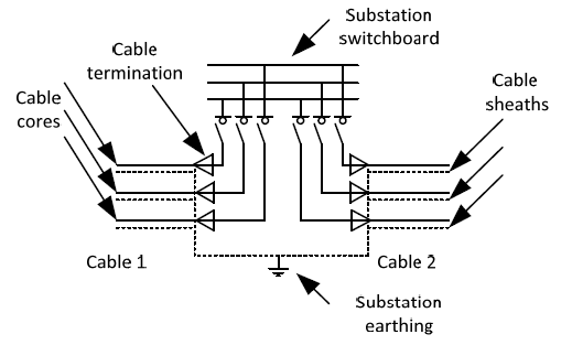
Figure 2 shows more details of the cable connection inside a secondary substitution. Each cable ends with a cable termination, which allows for cable core connection to a switchboard. The sheaths are led out of the cable termination, bonded together and connected via the earthing conductors to the earthing electrode. The earthing prevents stray voltages in lightly insulated sheaths in the event of a phase-to-earth fault occurring, or due to the transformer action of the conductor and sheath [12].
Cross-bonding recommended practices
The reduction of the current induced in the sheaths can be achieved in two ways. The first method is a single point bonding, where one of the sheath ends is earthed, while the other end remains disconnected. It results in the elimination of the induced current because the circuit remains open. The main disadvantage of such a solution is that sheath voltage at the unearthed end can rise to an unacceptably high value, especially during faults [2]. Therefore, the solution is acceptable only for short cable lines and it is rarely used in practice. The problem of sheath high voltage during faults can be reduced by indirect earthing of the cable sheaths by surge arresters (Sheath voltage limiters SVLs). An additional cable – earth conductivity conductor ECC is used to balance the potential between cable ends [7]. The solution is unacceptable for long-distance cables, because the installation of SVLs reduces sheaths voltages during faults, while sheath voltages can reach maximum permissible values [13] during normal line operation.
The solution which guarantees to reduce the sheaths currents and keep sheath voltages low during normal operation and during faults is the division of the cable length into three (or six, or nine, etc.) approximately equal sections. The sheaths are earthed at the beginning of the first section and at the end of the third section. In the two intermediate joints, the sheaths are crossed according to Fig. 3. As a result, three sheaths connected in series are associated with conductors of different phases, and consequently, for the balanced load, the sheath resultant voltage is close to zero. The solution is effective, however, it increases the investment cost. It requires installing nontypical insulation joints between cable sections. Sheaths can be cross-bonded using special link-boxes, which is typical for HV cables, while for MV cables bonding cables can be used directly between joints as shown in Fig. 3 [8].

While cross-bonding can be recommended and applied for newly built cable lines, the modernization of existing cable systems is problematic. It requires digging-up the cable in a specified location by removing some of the soil. To carry out such an operation it is necessary to know the burial depth and exact location of the cable route. Without this information, digging tools cannot be used effectively and the cable may be damaged. Moreover, in urban areas, dividing the existing cable line into sections of equal length can be impossible due to existing infrastructure i.e. roads, pipelines, property rights etc. Therefore, the paper discusses the alternative ways for cross-bonding, which can be applied for the existing MV cable lines.
Alternative Cross-bonding method for MV network
The idea of alternative cross-bonding assumes the limited intrusion on the existing cable line. The goal is to reduce the sheaths currents without digging-up of the cable and without installing the cross-bonding joints in the ground on the cable route. It can be done by changing the arrangement of the earthing system in the secondary substations.
The MV networks supply several numbers of secondary substations, and the distances between subsequent substation are relatively low, especially in the urban areas. Therefore, the substations can be chosen as places where the cable line is divided into three sections as for typical cross-bonding. The idea is presented in Fig. 4. The figure presents a diagram of an MV radial network supplying five substations. The sheaths are earthed only in two points i.e. in the supplying substation, at the beginning of the cable line L1, and at the end of the cable line L5, in substation 5. In all intermediary substations (substations 1-4) cable sheaths are not connected to the substation earthing system. In selected substations (e.g. substations 1 and 3) the cable sheaths are crossed. In that way, the cable line is divided into three sections.

The selection of cross-bonding points for the real MV networks can be a challenge, because of unequal cable line lengths between the subsequent substations. Moreover, the currents flowing in subsequent sections of the MV network would be different.
The sheath voltage induced along the specified length, for balanced system is equal to [7]:
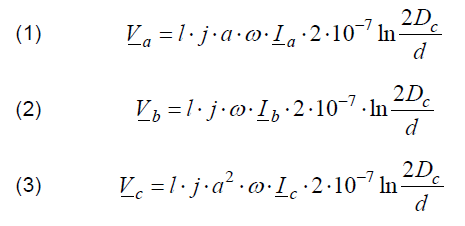
Where: l – cable length, Dc – axial spacing of adjacent cables, d – average sheath diameter, Va, Vb, Vc, – voltages induced in sheaths of cables in phases a, b, c respectively per one kilometre, Ia, Ib, Ic – current in cores of the cables, ω – the angular frequency of the system, a=ej120 .
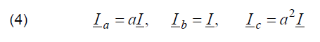
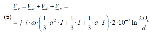
Assuming the same cable type and the same cable formation, which is typical for MV network, the voltages induced in the sheaths depends directly on the currents in the core cable and cable lengths. In conventional ideally cross-bonded line, the total voltage along cable ends can be reduced to value Vr which is the sum of sheath voltages along three sections of the cable. If the load is balanced:
then, the resulting voltage Vr would be zero:
In practice, the resulting voltage is not zero and low current flow in the sheaths is expected, because of unbalanced, and unequal currents along the line (due to distributed line capacitance), as well as unequal distances between cables along the route.
When applying the alternative cross-bonding method, as proposed in the paper, it should be noted that the currents flowing in the individual line sections (from a substation to the next substation) will not be equal. Therefore, to decide at which substation the cross-bonding should be made to reduce the resulting voltage Vr, it is not enough to simply divide the line into three equal sections. Not only the length of the sections must be taken for consideration, but also the load of the sections.
Assuming that the cable line supplies n substations, there are n sections of the cable line with different lengths. The sections will be assigned to a lengths set L (6). In every section of the line, there are different load currents, and they will be assigned to a currents set I (7).

The aim of cross-bonding sites optimization is dividing the length set L into three subsets, which will contain the cable line sections assigned to a particular cross-bonding sequence. The subsets will be noted as:
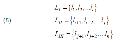
Hence, the substations where the sheaths cross-bonding are substations i and j.
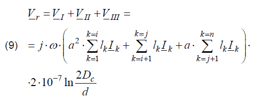
Assuming a balanced load in each section of the line, the induced voltage along the whole line is equal:
To reduce sheath currents the resulting voltage along the whole cable system should be as lowest as possible. This can be achieved for the condition:

This condition is difficult, or even impossible, to fulfil in the real power system hence the proposed alternative cross-bonding method will not result in decreasing sheaths current to zero and will not fully eliminate power losses in the sheaths. However, it is possible to partially equalize the sums of products of length and currents for the cable line sections assigned to a particular cross-bonding sequence.
Calculation example – simple radial network
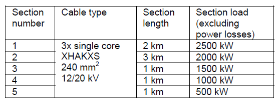
The first, very simple calculation example is based on the network model shown in Fig. 4. It is assumed, that all sections (from one substation to another) have lengths given in Table 1, and at each substation, power demand is 500 kW. This results in decreasing loads of subsequent line sections. The network nominal voltage is 15 kV. A summary of the assumptions for analysis is presented in Table 1.
Without making detailed calculations of current flow and voltage levels, it can be estimated that the sections currents are proportional to sections loads. If it is assumed, that current in the last section is equal, I5 = I, then currents in the previous sections would be I4 = 2 I, I3 = 3 I, I2 = 4 I, I1 = 5 I. According to the formula (10), the sums of products of length and currents for the cable line sections assigned to particular cross-bonding sequence should be equalized.
Table 1. Assumptions for analysis
The resulting values of products of section lengths and currents are presented in Table 2. It can be seen, that for a perfect cross-bonding, to satisfy equation (10), one-third of the total sum of products of section lengths and currents should be assigned to each cross-bonding sequence. One-third of the total sum of products of section lengths and currents should is equal to 9.33 I for the analyzed case. It is impossible to reach such a value using cross-bonding in substations only, but it is possible to obtain for each cross-bonding section values close to optimal. For the analyzed case, the optimal sites for cross-bonding are substations 1 and 2. In that way, the sum of products of section lengths and currents for each cross-bonding section are close to each other as possible and close to the optimal value of 9.33.
Table 2. Cross-bonding site analysis for the radial network.

The detailed analysis of the case was made on a model created in PowerFactory software. The cable system model for each section consists of three single-core cables per one cable line. Each cable is modelled by conducting and insulating layers in a coaxial arrangement. These layers represent the core and the sheath, separated by semiconducting and insulating layers. The couplings between the single-core cables are also modelled by determining the cable layout and spacing. The detailed description of the PowerFactory cable system model is provided in [14].
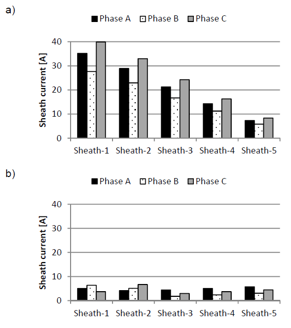
Two cases are compared. The first case is a typical network arrangement, where the sheaths are bonded and earthed in each substation, there is no cross-bonding. In the second case, sheaths are bonded and earthed in the supplying substation and in the last substation 5, and the crossing is done in substation 1 and 2, according to Table 2. Fig. 5 shows a comparison of sheaths currents for two cases. In the first case, where sheaths of each cable are bonded and earthed at the ends, the observed sheath currents are high. In the first, the most loaded cable section, the currents reach up to 40 A, which is about 40% of the cable core current. The lower the cable core current, the lower is the resulting sheath current. In the second case (Fig. 5-b) sheaths currents are significantly decreased in comparison to the first case. This proves that the proposed method leads to effective sheaths currents limitation. It is worth noting that the proposed crossing sites do not provide a perfect equalizing of induced sheaths voltages, although currents are considerably reduced. Sheath current reduction causes power losses reduction and increasing power transmission efficiency, which is very desirable. For the analysed network, the power losses in the whole network were reduced by 24%, from 21 kW to 16 kW, which is a very good result.
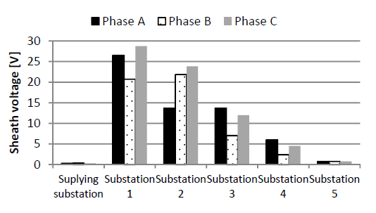
One of the most common reasons for earthing cable sheaths in multiple points is Distribution System operators’ (DSO) anxiety about the sheath induced voltages. The analysis of the sample case shows that sheath voltage levels are not high enough to pose a threat. In the analyzed case (Fig. 6) the sheath voltages do not exceed 30 V in the steady-state, which is lower than the permissible touch voltage 80 V [13]. During the earth faults, higher voltage values can be expected, therefore additional surge arresters may be needed to be installed at the substations where the sheaths are not earthed. This problem will not be discussed in the paper.
Calculation example – real open-loop network
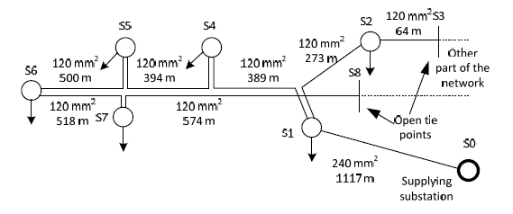
The next example is based on part of a real network in Poland. The network arrangement and its basic parameters are shown in Fig. 7. The network contains six secondary substations (S1, S2, S4, S5, S6 and S7) which supply customers via MV/LV transformers. This is an open-loop network arrangement and two open tie points are visible (Substations S3 and S8). The network is fed from supplying substation S0. All the cables are single aluminium core cables, with cross-section area of 120 or 240 mm2. The length of each cable is given on the diagram. The sheaths are made of copper tape, and the cross-section area for each cable is 50 mm2.
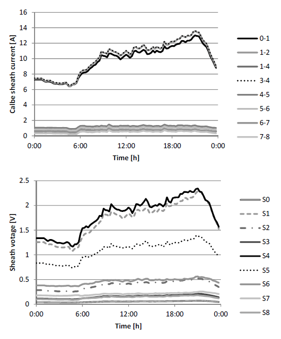
The substation load, taken for further consideration, is based on real measurements of secondary substation power demand taken during a one day in September of 2017. The resulting currents for each substation are shown in Fig. 8. The currents change during the day according to power demand variability. It is visible, that load profiles vary in shape and value for each substation.
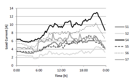
Figure 9 shows the calculation results of the cables core current and the sheath currents for the existing state i.e. sheaths of each cable section are bonded and earthed in the substations. It is visible, that loading of the core cables depends on the substations power demand and on network topology. The most loaded are cables close to the supplying substation i.e. 0-1 or 1-4, while only small charging current flows in the cables on route to the open tie points i.e. 2-3, 7- 8. The sheath currents correspond to the core currents.
Here the question arises how to account for the variable load in the cross-bonding sites selection process. The authors propose to use an average current value over the measurement period. This results in average currents presented in Table 3. The analysis shows, that the most loaded is the first cable section (from supplying Station 0 to Substation 1). It is also the longest section, therefore the product of length and average current for this section is much higher than for the other sections. This indicates that making an equal division of the length and the current products is impossible for the analyzed case. The optimal value (one-third of the total sum of lengths and currents products) is 23.11, while the calculated product for the first section is almost twice higher. Despite this, Table 3 presents a proposal to divide the network into three parts. According to the table, the recommended cross-bonding substations are S1 and S4. It is assumed that for safety reasons sheaths are bonded and earthed in substations where open tie points are S3 and S8.
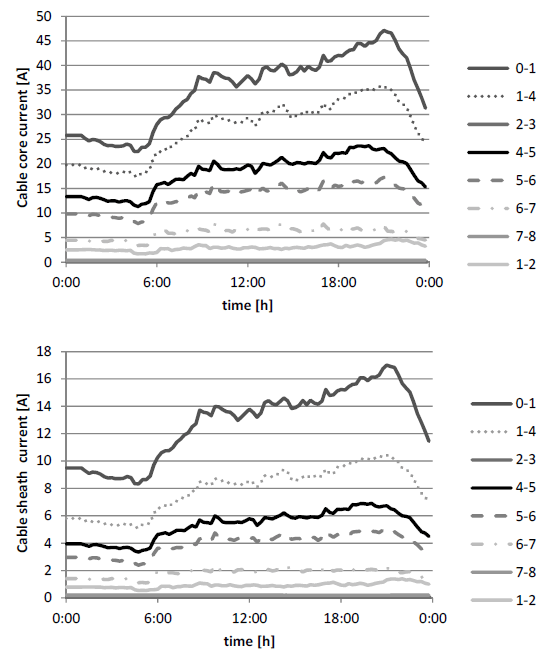
Table 3. Cross-bonding site analysis for the real open-loop network
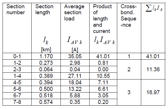
Fig 10 presents sheaths currents and sheaths voltages for a cross-bonded network (alternative cross-bonding method based on Table 3). A small current decrease (about 2 A) is visible for the first section (0-1). This is not a big change, but the considered network and the assumed load, do not give many opportunities. Moreover, the branch from substation 1 via substation 2 to substation 3 is relatively short, which creates an additional closed-loop (sheaths are bonded and earthed in tie point S3). Therefore, the sheath currents in sections 0-1-2-3 cannot be effectively reduced. The reduction of the sheaths current is visible in the remaining part of the network. On route from substation S1 to S8, the sheaths current is reduced to about 1 A. This results in a reduction of energy losses in the network for one day from 29.7 kWh to 27.3 kWh which is 8%.
It can be seen that the analysed network is lightly loaded. The measurement data, on which the analysis is based, were collected in the summer when power demand in Poland is usually lower than in winter. Therefore, for a heavier loaded network, the expected reduction of energy losses would be greater. In fact, the best optimisation results could be achieved if yearly load profiles of the MV/LV substation are known.
The daily energy losses reduction for the analysed small part of the network is 2.4 kWh. This value corresponds to the total length of the cable lines equals to 3.88 km. Therefore, the average daily energy losses reduction per kilometre can be estimated as about 0.6 kWh/km. If this factor is multiplied by the total length of MV cable lines of the single Distribution System Operator, the energy-saving can be roughly estimated. For one of the Polish DSOs, who’s total length of the MV cable lines is 13000 km, the daily energy savings can exceed 7 MWh.
The sheath voltage assessment was also done for the assumed daily load profiles. The sheaths voltages, which are presented in Fig. 10, remain at a safe level, significantly below the limit of 80 V.
Conclusions
The alternative cross-bonding method is an interesting solution for an existing network. It allows for reducing the overall power losses in the network. The solution is cost-effective because sheaths cross-bonding can be done directly at cable line termination in the substation building. There is no need to dig-up the cable and no need to install extra joints and link boxes.
The effectiveness of the power losses reduction depends on network arrangement and its load. The heavier loaded the cable lines are, the greater losses decrease can be expected. The most complicated cases to optimise are open-loop networks with short branches. The sheaths bonding and earthing in the last substation in the branch creates sheath closed loops, where the reduction of currents can be impossible. Despite this, using the proposed method, it is possible to limit losses.
The best results in decreasing the power losses are visible for a single route cable lines (without branches), where sheaths are bonded and earthed only in two points, at the beginning, and at the end of the line.
The decision to apply sheath cross-bonding in the network has to be aided by network analysis, based on detailed information of the network arrangement and the load profiles. The load profiles are particularly important to ensure analysis accuracy and assess solution profitability. Roughly estimated energy savings for one of the Polish DSOs can reach up to 7MWh daily which turns into savings of about 2.5GWh yearly.
REFERENCES
[1] Popovic L M. Practical Methods for Analysis and Design of HV Installation Grounding Systems. Elsevier; 2018. https://doi.org/10.1016/C2017-0-01221-1.
[2] Andruszkiewicz J, Lorenc J, Łowczowski K, Weychan A, Zawodniak J. Energy losses’ reduction in metallic screens of MV cable power lines and busbar bridges composed of singlecore cables. Eksploatacja i Niezawodnosc – Maintenance and Reliability 2019; 22:15–25. https://doi.org/10.17531/ein.2020.1.3.
[3] Sobral A, Moura Â, Carvalho M. Technical Implementation of Cross Bonding on Underground High Voltage Lines Projects. 21st International Conference on Electricity Distribution, vol. 21, p. 6–9. Frankfurt 2011.
[4] Dobrzynski K, Lubosny Z, Klucznik J, Noske S, Grala J. Cross- Bonding of MV Cable Lines for Energy Losses Decrease. Acta Energetica 2019 2/39. https://doi.org/10.12736/issn.2330-3022.2019204.
[5] Li L, Yong J, Xu W. Single-Sheath Bonding—A New Method to Bond/Ground Cable Sheaths. IEEE Transactions on Power Delivery 2020;35:1065–8. https://doi.org/10.1109/TPWRD.2019.2929691.
[6] CIGRE Working group B1.18. Special bonding of high voltage power cables. 2005.
[7] IEEE Guide for Bonding Shields and Sheaths of Single-Conductor Power Cables Rated 5 kV through 500 kV. 2014. https://doi.org/10.1109/IEEESTD.2014.6905681.
[8] Kehl L, Meier R, Quaggia D. Cross-bonding for MV cable systems: advantages and impact on accessories design. 25th International Conference on Electricity Distribution, Madrid 2019, p. 3–6.
[9] Jakubowski J, Pasniewski M, Kibler M. Cross-Bonding in Middle Voltage Distribution Grids, as a Method of Energy Efficiency Improvement. 21-th International Conference on Electricity Distribution, Budapest 2011.
[10] Gouramanis K V., Stasinos K, Papagiannis G K, Kaloudas C G, Papadopoulos T A. Methodology for the selection of longmedium-voltage power cable configurations. IET Generation, Transmission & Distribution 2013;7:526–36. https://doi.org/10.1049/iet-gtd.2012.0165.
[11] Prévé C. Protection of Electrical Networks. London, UK: ISTE; 2006. https://doi.org/10.1002/9780470612224.
[12] Bayliss C, Hardy B. Transmission and Distribution Electrical Engineering. Elsevier Ltd; 2007. https://doi.org/10.1016/B978-0-7506-6673-2.X5000-9.
[13] EN 50522:2010 Earthing of power installations exceeding 1 kV A.C.
[14] PowerFactory Technical Reference Documentation – Cable System. DIgSILENT 2021.
Author: dr hab. inż. Jacek Klucznik, Politechnika Gdańska, Wydział Elektrotechniki i Automatyki, ul. G. Narutowicza 11/12, 80-233 Gdańsk, E-mail: jacek.klucznik@pg.edu.pl;
Source & Publisher Item Identifier: PRZEGLĄD ELEKTROTECHNICZNY, ISSN 0033-2097, R. 99 NR 2/2023. doi:10.15199/48.2023.02.10
