Published Vijayshree G1, Sumathi S2, RNSIT, Bangalore,Karnataka,India(1). RNSIT, Bangalore,Karnataka, India(2)
Abstract – This paper proposes a power system network modeled using a microgrid, integrated with wind and solar photovoltaic (PV) resources, along with the battery energy storage system (BESS) connected to the three-phase grid feeding the linear and nonlinear load. The simulation is carried out with unit vector and instantaneous reactive power control algorithm for series and shunt active power filter respectively. The power quality improvement is analyzed for the voltage sag, swell, and harmonics for system with load variation and without load variation. The performance analysis is based on voltage & current THD, voltage & current RMS, and power and power factor analysis. The THD for comparison is represented in form of bar chart to show the effective performance of control algorithm proposed using PWM method and hysteresis controller.
Streszczenie. W artykule zaproponowano modelowanie sieci elektroenergetycznej za pomocą mikrosieci zintegrowanej z wiatrowymi i słonecznymi źródłami fotowoltaicznymi (PV) wraz z bateryjnym systemem magazynowania energii (BESS) podłączonym do sieci trójfazowej zasilającej obciążenie liniowe i nieliniowe. Symulacja prowadzona jest za pomocą wektora jednostkowego i algorytmu regulacji mocy biernej chwilowej odpowiednio dla filtru mocy czynnej szeregowego i bocznikowego. Poprawa jakości energii jest analizowana pod kątem zapadów, wzrostów napięcia i harmonicznych dla systemu ze zmiennym obciążeniem i bez zmiennego obciążenia. Analiza wydajności opiera się na THD napięcia i prądu, wartości skutecznej napięcia i prądu oraz analizie mocy i współczynnika mocy. THD dla porównania przedstawiono w postaci wykresu słupkowego, aby pokazać efektywne działanie algorytmu sterowania zaproponowanego przy użyciu metody PWM i regulatora histerezy. (Poprawa jakości energii elektrycznej w systemie generacji rozproszonej w warunkach zmiennego obciążenia z wykorzystaniem PWM i regulatora histerezy)
Keywords: microgrid, distributed generation, power quality, UPQC
Słowa kluczowe: mikrosieci, rozproszone źróda energii, PWM
Introduction
Power quality (PQ) is used to assess and maintain the good quality of power at different levels (generation, transmission, distribution, and utilization) of the AC electrical power system. Power quality has become a challenging area of research in electrical engineering. Power quality is a combination of current and voltage quality. The voltage or current deviation from the ideal value is the disturbance of power quality. However, distinguishing between the voltage and current disturbances in the power system is difficult because for different customers different event leads to different disturbances. Therefore, in general, power quality is related to disturbances in voltage, current, frequency, and power factor. The electrical network considered for power quality assessment includes a three-phase programmable source connected to a microgrid with wind and solar PV resources along with battery storage. The system is connected to the non-linear load and linear load for power quality analysis. In [1] author explains generalized integrator controller which provides unity power factor (UPF) operation, load balancing, harmonics mitigation, and reactive power compensation for three phases single-stage grid interfaced solar energy conversion system. Different methods of analysis that describes the harmonic behavior of the electrical network and these data are reported to provide suitable mitigation strategies in a real-time operation is explained in [2]. The author in [3] explains the implementation of distributed generation operated for nonlinear and unbalanced load with different source conditions using enhanced Instantaneous Power Theory. The use of renewable energy sources has different environmental benefits and is also economical when compared with the traditional source of power generation [4]. The integration and control of renewable energy in electric power systems is mathematically modelled in [5] .In [6] ,a modified p-q theory-based control that implements a solar photovoltaic (PV) array integrated unified power quality conditioner (PV-UPQC-S) for analysis of the steady and dynamic performance of the system is explained. The paper [7] proposes a three-phase transformer less Hybrid Series Active Filter (THSeAF) in combination with SRF and PQ theory to provide suitable mitigation for power quality issues. [8] explains about the stationary and non-stationary power quality disturbance which is mitigated using variational mode decomposition (VMD) and decision treebased detection method which is capable of accurate detection, estimation, localization, and classification of all kinds of PQ disturbances in both noisy and noise-free cases. [9] explains how fluctuation in photovoltaic (PV) power plants affects the power quality and stability of the grid along with the increasing penetration of PVs. The addition of an energy storage system resolves this issue. The importance of battery parameter state of charge is taken care of to ensure the stability of the energy storage system. In [10], different positions of UPQC placement for better performance are analyzed. A Synchronous reluctance generator is used as an input to feed linear and nonlinear loads with an adaptive neural network-based control algorithm to improve power quality which mitigates some power quality problems such as harmonic suppression, and load balancing, reduction in frequency variation and voltage regulation[11]. Passive and active filters in providing power quality compensation, the advantages and disadvantages of both types of filters are explained and justify that the active power filter is more advantageous [12].
Problem formulation
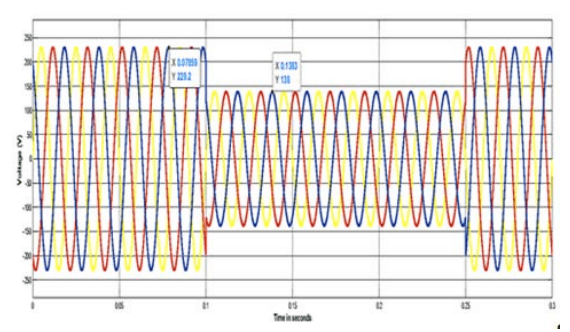
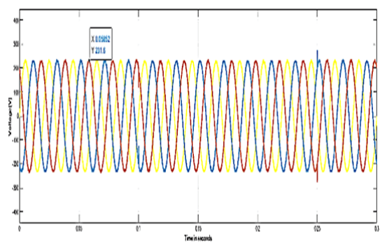
The three-phase voltage source of 415V, 50 Hz is integrated with a Microgrid designed with solar and wind generation connected to linear and nonlinear load . The magnitude of the voltage at the microgrid is maintained the same as the supply voltage as it is connected in parallel. The supply voltage is observed to be 229.2 volts phase to phase as shown in figure 1, at t=0s to t=0.1s. The voltage sag of 0.6 pu is introduced at t= 0.1s to t= 0.25s whose magnitude is reduced to 138V as indicated in figure 1, at t= 0.1s to t= 0.25s.Its corresponding RMS voltage is shown in figure 2. The power system is connected to a nonlinear load of a three-phase bridge rectifier with R= 40Ω and L=1e-4 H through a transmission line of resistance 0.002 ohms and inductance of 1e-5 H. At t=0.02 s, the linear load is added to the system to analyze the effect of a sudden change in load on the power system considered. The decrease in voltage and increase in current from t= 0.02s to t=0.16s, due to the addition of load is shown in figure 3 and figure 4.


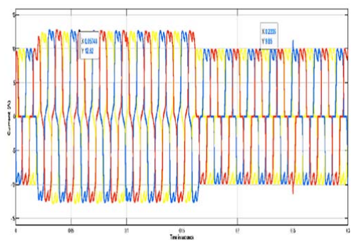
The RMS current waveform for variation in load is as shown in figure 5 where the load is added at t=0.02 s to t= 0.16s. The load is removed at t=0.16s, and hence the magnitude of the current decreases at t=0.16s. At t= 0.1 s, the voltage sag of 0.6 pu is introduced which indicates the reduction in power at that instant as shown in figure 6. It is observed in figure 7, that the power factor without UPQC compensation is 0.94.


Design of unified power quality controller (UPQC)
In view of improving the system performance by mitigating the defined power quality issue in section 2, UPQC is designed with a unit vector algorithm for series active power filter (APF) and Instantaneous reactive power theory for shunt active power filter. The gate pulse is generated using the PWM technique in series APF and PWM and the hysteresis controller in the shunt active filter. The MATLAB simulation model designed for the defined power system network is shown in figure 8.
Three-phase voltage source in parallel to the microgrid at the supply terminal is connected to a three-phase load (both linear and nonlinear) through the transmission line. The UPQC comprising of series and shunt compensator is as shown in figure 8. The series active filter is designed using a unit vector control algorithm. The single phase input is fed to the phase-locked loop with the gain of 0.005 to obtain the value of wt. The three-phase voltage is derived by using the equation (1) – (3) which is then compared with the supply voltage to determine the error in voltage that derives the switching signals using the method of pulse width modulation.
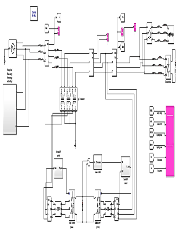

The series active filter is connected to the supply terminal using three phases linear transformer with 12 terminals with three phases rated power of 10e6VA, with 50 Hz frequency. The winding RMS voltage is set to 100V, R= 0.002pu and X= 0.00005 pu.
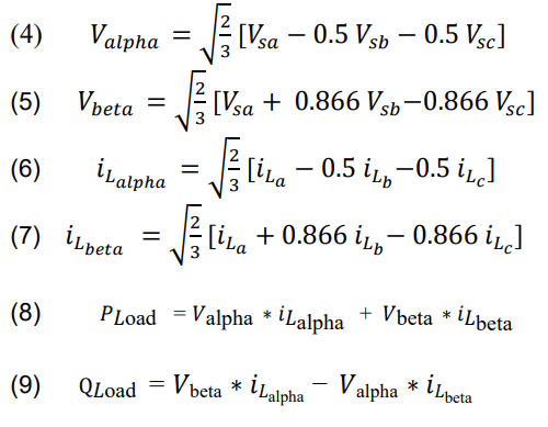
The design of shunt APF is done using instantaneous reactive power theory (IRPT) with two different control algorithms for the generation of switching signals. One uses a PWM controller and the other uses a hysteresis controller. The IRPT is designed using supply voltage and load current. The reference current is obtained using supply voltage, load current, and control signal obtained using a PI controller. The reference current is obtained using the equation (4) – (9)
The series and shunt compensation is provided by using a MOSFET-based universal bridge inverter connected along with the interfacing inductor of 4e-3 H. The simulation results after providing UPQC compensation for the problem formulated are shown in figure 9. In figure 9, at t= 0.05s and t=0.15s, with a magnitude of voltage 231.6 V. Its corresponding RMS component of voltage is shown in figure 10.


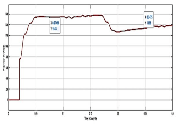
The current waveform is as indicated in figure 11. The magnitude of current is 14.54 A at t= 0.02s to t=0.16s. At t=0.16s the linear load is removed and hence the magnitude of the current is reduced to 12.3A. After UPQC compensation the power waveform is as shown in figure 12. The magnitude of power is 1543 W at t= 0.02s to t= 0.16s. As the load is removed at t=0.16s, the power magnitude also reduces to 1333 W. The power factor after UPQC compensation is as shown in figure 13, where the power factor is improved to 0.98 compared to 0.94 without UPQC compensation. As per IEEE standards 519-1992: For general distribution system, current distortion limits obtained by the simulation performed lie within the limit.

The comparison of simulation output obtained from PWM and hysteresis controller for system without variation in load and with variation in load for different magnitudes of voltage sag and swell and harmonic orders are as tabulated in table 1 to table 6.
Table 1. THE MAGNITUDE OF FUNDAMENTAL COMPONENT OF VOLTAGE AND CORRESPONDING THD FOR VOLTAGE SAG AND SWELL WITHOUT LOAD CHANGE.
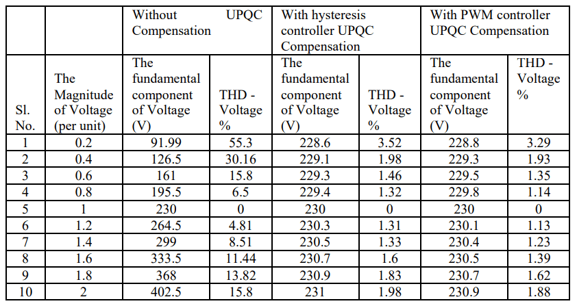
Table 2. THE MAGNITUDE OF FUNDAMENTAL COMPONENT OF CURRENT AND CORRESPONDING THD FOR VOLTAGE SAG AND SWELL WITHOUT LOAD CHANGE.

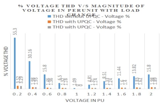
Table 3. THE MAGNITUDE OF FUNDAMENTAL VOLTAGE COMPONENT AND CORRESPONDING THD FOR VOLTAGE SAG AND SWELL WITH LOAD CHANGE.

Table 4. THE MAGNITUDE OF FUNDAMENTAL COMPONENT OF CURRENT AND CORRESPONDING THD FOR VOLTAGE SAG AND SWELL WITH LOAD CHANGE.

Table 5. THE MAGNITUDE OF FUNDAMENTAL COMPONENT OF CURRENT AND CORRESPONDING THD FOR HARMONICS

Table 6. THE MAGNITUDE OF FUNDAMENTAL COMPONENT OF VOLTAGE AND CORRESPONDING THD FOR HARMONICS.

Conclusion
The aim of power quality improvement is to provide pure sinusoidal voltage and current to the consumers. The problem formulated includes the addition of load at the distribution end, introducing voltage sag, swell, and harmonics of a different order which is as shown in figure 1 – figure 4.
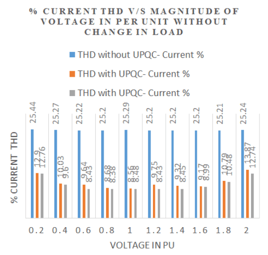
The above-defined power quality-related issues are mitigated using a combination of shunt and series active power filters called UPQC with PWM and hysteresis controller as shown in figure 9-figure 11.The bar chart representation of THD for voltage and current without UPQC, with UPQC PWM and UPQC Hysteresis is shown in figure 14 –figure17. It can be concluded that PWM controller gives good performance when compared to hysteresis controller. The power and power factor, corresponding RMS voltage, and current is analyzed to show the effectiveness of UPQC designed to improve the power quality.


REFERENCES
[1] Priyank Shah, Ikhlaq Hussain, Bhim Singh, Ambrish Chandra, Kamal Al Haddad “GI Based Control Scheme for Single Stage Grid Interfaced SECS for Power Quality Improvement”, 2018, IEEE Transactions on Industry Applications, 1–1. DOI:10.1109/TIA.2018.2866375
[2] Sean Elphick, Vic Gosbell, Vic Smith, Sarath Perera, Philip Ciufo, Gerrard Drury, “Methods for Harmonic Analysis and Reporting in Future Grid Applications” 2016, IEEE Transactions on Power Delivery, 1–1. doi:10.1109/TPWRD.2016.2586963. Farnaz Harirchi, Marcelo Godoy Sim˜oes, “Enhanced Instantaneous Power Theory Decomposition for Power Quality Smart Converter Applications”, IEEE transactions on power electronics, vol.33, no.11, November 2018.
[3] Marco Mauri, Luisa Frosio and Gabriele Marchegiani,“ Electrical generation and distribution systems and power quality disturbance” , ISBN: 978-953-307-329-3, November 21st, 2011.Web of Science publication.
[4] Ali Keyhani, Mohammad N. Marwali, Min Dai, “Integration of green and renewable energy in electric power systems”, 19 November 2009, Print ISBN:9780470187760 |Online ISBN:9780470556771 DOI:10.1002/9780470556771, Copyright © 2010 John Wiley & Sons, Inc.
[5] Sachin Devassy, Bhim Singh, “Modified p-q Theory Based Control of Solar PV Integrated UPQC-S”, 2016 IEEE Transaction on Industry Applications, DOI: 10.1109/IAS33229.2016
[6] Alireza Javadi, Member, IEEE, Lyne Woodward, Member, IEEE, and Kamal Al-Haddad, Fellow, IEEE, “Real-time Implementation of a Three-phase THSeAF Based on VSC and P+R controller to Improve Power Quality of Weak Distribution Systems”, DOI 10.1109/TPEL.2017.2697821, IEEE transaction on Power Electronics. Pankaj D. Achlerkar; S. R. Samantaray; M. Sabarimalai Manikandan, “Variational Mode Decomposition and Decision Tree Based Detection and Classification of Power Quality Disturbances in Grid-Connected Distributed Generation System”, IEEE Transactions on Smart Grid ( Volume: 9, Issue: 4, July 2018), DOI: 10.1109/TSG.2016.2626469.
[7] Mingyu Lei, Student Member, IEEE, Zilong Yang, Yibo Wang, Honghua Xu, Lexuan Meng, Member, IEEE, Juan C. Vasquez, Senior Member, IEEE, Josep M. Guerrero, Fellow, IEEE, “An MPC Based ESS Control Method for PV Power Smoothing Applications”, IEEE transaction on Power Electronics, DOI:10.1109/TPEL.2017.2694448, PP 99,1-1, April 2017.
[8] Shafiuzzaman K. Khadema, Malabika Basu, Michael F. Conlon, “A comparative analysis of placement and control of UPQC, in DG integrated grid-connected network”, Sustainable Energy, Grids and Networks, Elsevier publication, 2016.
[9] Arya, Sabha Raj; Kant, Krishan; Niwas, Ram; Singh, Bhim; Chandra, Ambrish; Al-Haddad, Kamal (2014) “Power quality improvement in isolated distributed generating system using DSTATCOM”, IEEE 2014 IEEE Industry Applications Society Annual Meeting – Vancouver, BC, Canada (2014.10.5-2014.10.9)] 2014 IEEE Industry Application Society Annual Meeting -, (), 1–8. doi:10.1109/ias.2014.6978417
[10]Bhim Singh, Ambrish Chandra, and Kamal Al-Haddad, “Power Quality Problems and Mitigation Techniques”, First Edition. © 2015 John Wiley & Sons, Ltd. Published 2015 by John Wiley & Sons, Ltd.
[11]Vijayshree. G, “Improvement of Power Quality Using Instantaneous Reactive Power Theory for Controlling Shunt Active Filter,” 2021 International Conference on Circuits, Controls and Communications (CCUBE), 2021, pp. 1-6, doi: 10.1109/CCUBE53681.2021.9702742.
Source & Publisher Item Identifier: PRZEGLĄD ELEKTROTECHNICZNY, ISSN 0033-2097, R. 99 NR 3/2023. doi:10.15199/48.2023.03.25
