Published by 1. M.S. ALI 1,2, 2. Mahidur R SARKER 3, 3. Ahmad ASRUL IBRAHIM 1, 4. Ramizi MOHAMED1, 1Faculty of Engineering and Built Environment, Universiti Kebangsaan Malaysia, Bangi 43600, Malaysia; 2Electrical Engineering Department, German-Malaysian Institute , Jalan Ilmiah, Taman Universiti,43000, Kajang, Selangor, Malaysia; 3Institute of IR 4.0, Universiti Kebangsaan Malaysia, 43600 UKM Bangi, Selangor, Malaysia. ORCID. 1. 0000-0001-7142-7755, 2. 0000-0002-5363-6219, 3. 0000-0003-4997-3578, 4. 0000-0003-1534-6760
Abstract. Flywheel motor generator (FMG) system or normally called a flywheel energy storage system (FESS) becomes the main consideration in power stability of micro-grid, transportation, portable power supply, and renewable energy power station such a solar or wind. Its contribution in stabilizing power production and reducing power consumption is undeniable. High power consumption in the small-scale industry especially sprays dryer factory become a major issue due to high-cost production. Load such a heating element needs more power consumption to operate and achieve the desired temperature. High-efficiency FMG can be an alternative power backup to reduce power consumption by serving a separate supply to the load (heater). This paper is focused on modeling and simulation of the FMG system. The simulation result shows that the system proposed can provide very high efficiency with stable output power and also can reduce the cost of production due to power consumption reduction.
Streszczenie. System silnika generatora z kołem zamachowym (FMG) lub zwykle nazywany systemem magazynowania energii koła zamachowego (FESS) staje się głównym czynnikiem stabilności energetycznej mikrosieci, transportu, przenośnego źródła zasilania i elektrowni energii odnawialnej, takiej jak energia słoneczna lub wiatrowa. Jego wkład w stabilizację produkcji energii i zmniejszenie zużycia energii jest niezaprzeczalny. Wysokie zużycie energii w przemyśle na małą skalę, zwłaszcza w fabryce suszarek rozpyłowych, staje się poważnym problemem ze względu na wysokie koszty produkcji. Obciążenie takiego elementu grzejnego wymaga większego zużycia energii do działania i osiągnięcia pożądanej temperatury. Wysokowydajny FMG może być alternatywnym zasilaniem awaryjnym w celu zmniejszenia zużycia energii poprzez dostarczanie oddzielnego zasilania do obciążenia (grzałki). Artykuł koncentruje się na modelowaniu i symulacji systemu FMG. Wyniki symulacji pokazują, że proponowany system może zapewnić bardzo wysoką sprawność przy stabilnej mocy wyjściowej, a także może obniżyć koszty produkcji dzięki zmniejszeniu zużycia energii. (Wysokowydajny model generatora silnika z kołem zamachowym ze sterowaniem przemiennikiem częstotliwości)
Keywords: Simulation, modelling, flywheel, motor generator, power consumption, voltage stability, frequency stability.
Słowa kluczowe: silnik z kołem zamachowym,.zasobnik energii
Introduction
The increase in the use of electric power has led to high monthly electricity bill rates which is a major issue for domestic and small-scale industry [1][2]. Typically, this occurs when a heater or air conditioning load is used for a long period of time. Especially in the food industry that converted liquid to powder which uses high temperature [3][4]. The high cost of electricity causes the profit to be very low. Extremely hot weather conditions in public buildings such as mosques or others invite high electricity consumption. This is due to the use of air conditioners in proportion to the attendance of many guests. This has caused public houses to have difficulty paying their monthly electricity bills. Therefore, this problem needs to be resolved immediately to reduce the rate of electricity consumption at the rate that consumers can afford.
This study aims to produce an electricity generation system that can reduce electricity bills. This means that with the use of a separate electricity generating system, the electricity consumption can be reduced [5]. Basically, the motor will drive the generator, and the generator will generate electricity. The addition of flywheels to the generating system will cause the mechanical energy generated from the motor and generator rounds to be stored and converted to electrical power [6][7]. The inertia effect of the motor flywheel and generator will be delayed even when the power supply to the motor is disconnected. Here, electricity can be saved apart from the use of low-speed generators that generate electricity with a low- speed motor.
In [8], the author obtained that more electrical output can be produced by using a flywheel. This system of FMG can give extra electrical power without the use of any extra equipment and offer environmentally friendly and nonhazardous. The system FMG can be used in various applications especially household, industrial and it increases the efficiency of traditional electrical systems [9]. In [10], the author studied flywheel energy storage system powered by wind turbine and diesel generator in isolated micro-grid to improve the power quality of the system. The topology of the hybrid system consists of a simulated winddiesel power system and flywheel energy storage system [11][12]. In this study, an asynchronous machine is used to drive the flywheel in order to attain robustness and offered low cost. The bidirectional power converter is used to control the speed of the electrical machine when acting as a motor, then controlled the output voltage when in generator mode. The bidirectional power converter is also known as back to back converter [13]. DC link in the circuit is purposely to stabilize the voltage. This bidirectional power converter is controlled by pulse width modulation (PWM) in the voltage source inverter (VSI) [14][15]. The flywheel coupling is direct to the electrical machine store mechanical energy when an electrical machine in motor mode, then convert to electrical energy when electrical energy in generator mode [16]. As result, by actuation of the flywheel in the system make improvement in power quality.
In [17], the author stated that the flywheel system stores energy at 5kWh within a speed range of 10,000-20,000 rpm and an accelerating torque of 6.7Nm. The passive magnetic bearing has been used to reduce the run-down losses of the system. By enclosing the flywheel in a vacuum chamber can be mitigated the rotor drag losses. This study analysed that the fluctuation of the DC-bus voltage due to load instabilities is limited to 3% and recovered within 40-45 ms. In [18], the author addressed that an asymmetrical six-phase induction motor that has been used to drive a flywheel can improve system reliability while supporting critical loads. Under the disconnection phase, the machine can function properly proved by simulation and experiment results. The rating of the switching device has been reduced compared to applying a normal three-phase motor. This system is suitable for medium voltage applications.
In [19], the author studied losses in flywheel energy storage systems. The system consists of the flywheel, an electrical machine, and a bidirectional converter/controller. The losses in this system were recognised as mechanical losses (drag, bearing friction), electrical losses (hysteresis, eddy current, copper) and power converter losses (switching, conduction) which is the magnitude of each loss depends on the operating conditions such as motor speed, dc bus voltage, switching frequency and load current. This study proved that the bearing friction loss in the flywheel and hysteresis loss in the machine is proportional to speed. Meanwhile, the drag loss in the flywheel and eddy current loss in the machine are proportional to the square of the speed. All these losses can be reduced by improving the efficiency of the system by the usage of a two-pole machine apply vacuum enclosure for rotating part and usage of ZVT/ZCT technique to reduce switching losses in power converter.
In [20], the author designed the flywheel energy storage system for space application. There are two regions in the orbital path of the satellite which are the dark and bright regions. The bright region can use a solar panel to provide energy but the dark region needs a flywheel energy storage system to maintain the power. In this study, brushless DC (BLDC) was used to drive flywheel due to high efficiency, high reliability, low weight, high power density, and high speed. However, there is a dramatic increased of current due to mechanical resonance will cause damage to the power system. Therefore, PI control was used to control the speed of BLDC with an effective current reference method to prevent the current spike occurred during mechanical resonance which BLDC runs at 20krpm in the vacuum condition. This experiment proved that the PI control can protect the power system from damage due to a short time current spike.
In [21], the author indicated that the combination of high temperature superconducting magnetic suspension with the integrated design of flywheel energy storage system can provide high efficiency and no additional losses. High temperature superconducting magnetic suspension is consists of a YBaCuO cylinder with axial anisotropy (external diameter – 31 mm, internal diameter – 25 mm, height 30 mm) as stator and disk-shaped nonmagnetic hull with three fixed rings FeNdB permanent magnet with axial magnetization as a rotor. This proposed design can be used on wind power stations, in the power supply systems for industry and transportation. Integration development of this system provides a stable levitation of the flywheel, allows to non-contact regulate the force of magnetic thrust bearing in a vacuum chamber, to perform an initial centering of the flywheel, and to put into operation a safety bearing in case of accidents. The main objective of this design is to create no additional losses due to magnetic hysteresis, no reactive moments, small winding inductance, and high specific power indicators due to the large value of the magnetic induction in the gap. The result of this experiment shows that there are no additional energy losses in storage mode and an electromagnetic time constant is low.
System configuration and mathematical model
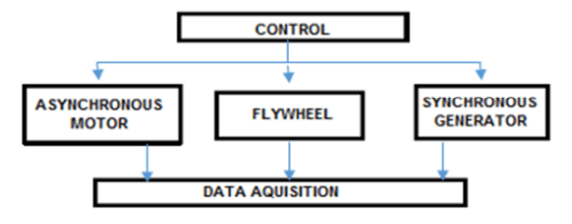
The general system configuration of the FMG System studied in this paper is as shown in Fig. 1. The flywheel is coupling directly with an asynchronous motor and synchronous generator. This coupling makes the flywheel, motor, and generator run synchronously at the same speed. A frequency inverter controls the speed of the flywheel, motor, and generator. A frequency inverter is to maintain the speed of the flywheel, motor and generator at the optimum value needed to maintain the generator voltage. Data acquisition used to get data from the generator and motor. An asynchronous motor is a Squirrel Cage motor type which is three phases induction motor that can provide high speed and torque. The synchronous generator is a high-efficiency generator that can give constant voltage with different torque. Here, the flywheel integrated with the motor and generator to support the electrical energy conversion. The flywheel still continues to rotate even the motor already swift off.
A simplified topology of the FMG connected to an electrical supply shown in Fig. 2. This studied topology is lab scale specification. The three phases supply 450V/50Hz is a power supply connected to breaker and transformer 240V/50Hz. The transformer secondary is in star connection. The frequency inverter connected to the life and neutral of a transformer. The frequency inverter 0.3kW used to control the speed of squirrel cage motor o.5hp/400V/50Hz with the nominal speed at 2800rpm. The flywheel parameter is setting together with the motor parameter which is 60cm for radius and 2kg/8kg for mass at 0.178kgm2/0.356kgm2. The frequency inverter can provide ramp mode and control the speed of a motor by changing frequency. This frequency inverter circuit consists of a full-wave rectifier and three phases full-bridge inverter. So, the incoming the frequency inverter is a single phase and the output is three-phase.
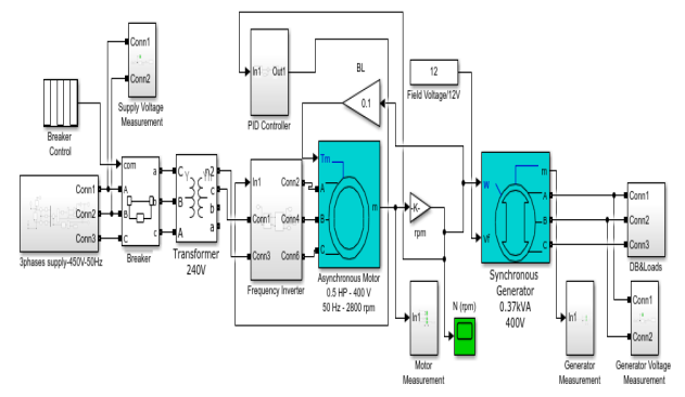
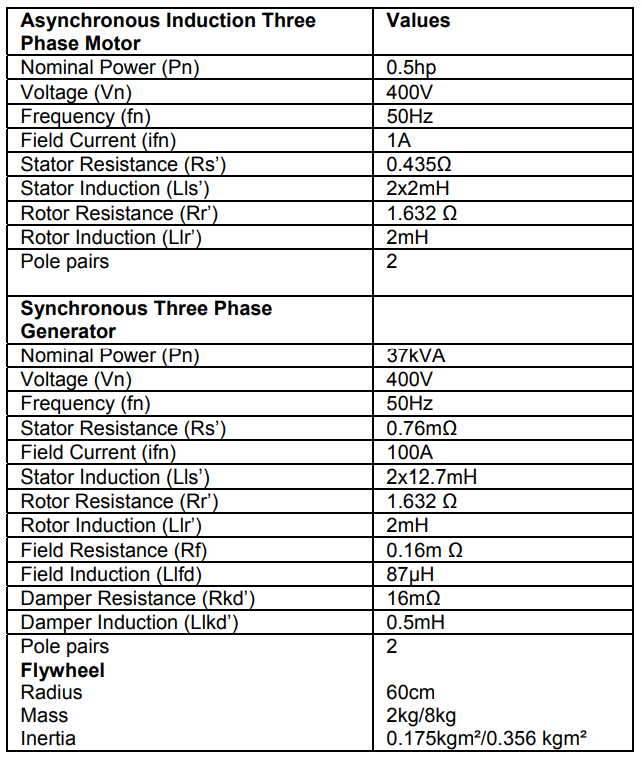
Table 1 shows the simulation parameter of an asynchronous induction three-phase motor and synchronous generator. An asynchronous motor used for this study can operate at 0.373kW and nominal speed at 2800rpm. An asynchronous motor selected for this experiment because cheaper compare with a permanent magnet motor which is very expensive. Therefore, the frequency inverter used to serve this motor must be higher than 300W. Whereby the synchronous generator used can generate a high voltage at low rpm with nominal power at 299kW and 0.8 power factor. Two different weights of flywheel user in this study are 2kg and 8kg with the same diameter. The inertia of the flywheel calculated by using the formula:
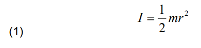
where I is Inertia, ½ is constant for solid cylinder flywheel, m is the mass of flywheel, r is the radius of flywheel.
Table 1. Parameter of asynchronous motor, synchronous generator and flywheel
The testing circuit diagram as shown in Fig 3 is used to analysis the system. From this testing circuit, the effect of the flywheel with different sizes and weights can be analyzed [22]. From this testing circuit also, the synchronization of the motor and generator can be measure. All the data measurements of the motor and generator such as stator current, torque, speed, input, and output voltage are being measured as shown in this figure. All measurements consist of a multi-meter to display the root mean square (RMS) value and the scope to plot the graph. The voltage supply also can be set according to the motor specification by changing the parameter of the supply relay three-phase.

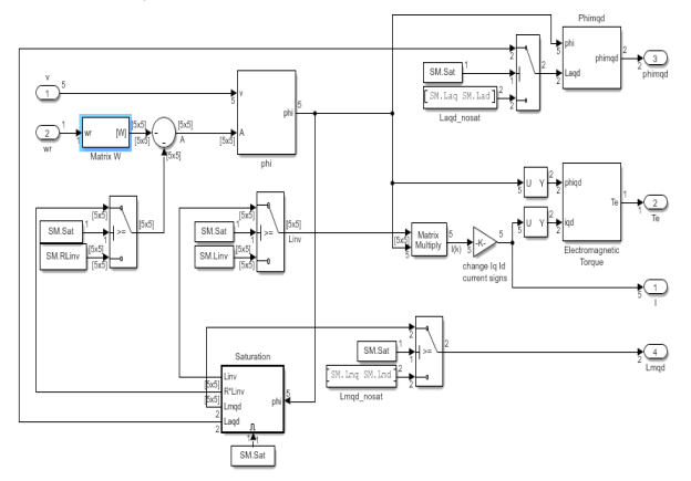
The detailed Simulink model for a synchronous generator as shown in Fig 4 used to generate voltage. This model is referring to mathematical model formula:
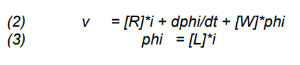
where R is a diagonal matrix ( nState, nState) of winding resistances in d q axis, L is the matrix ( nState, nState) of winding self, and mutual inductances in d q axis.
• W is matrix (nState, nState) depending on rotor speed wr, all zero except W (1, 2) = wr,W (2, 1) = –wr
• v is voltage vector = [ vq vd vfd vkd vkq (vkq2) ],
• phi is flux linkage vector = [ phiq phid phifd phikd phikq1 (phikq2) ], (state variable)
• i is current vector = [ iq id ifd ikd ikq1 (ikq2) ],
if RotorType = Salient-Pole, nState = 5
if RotorType = Round, nState = 6
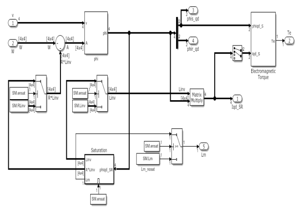
The detailed Simulink model for Asynchronous Motor as shown in Fig 5 used to drive the generator and flywheel. This model is referring to the mathematical model formula:

where: R is diagonal matrix ( nState, nState) of winding resistances in d q axis
• L is matrix ( nState, nState ) of winding self and mutual inductances in d q axis
• W is matrix (nState, nState) depending on rotor speed wr, all zero except W (1, 2) = wr,W (2, 1) = -wr
• v is voltage vector = [ vq vd vfd vkd vkq1 (vkq2) ],
• phi is flux linkage vector = [ phiq phid phifd phikd phikq1 (phikq2) ], (state variable)
• i is current vector = [ iq id ifd ikd ikq1 (ikq2) ],
if RotorType = Salient-Pole, nState = 5
if RotorType = Round, nState = 6
Results and discussion
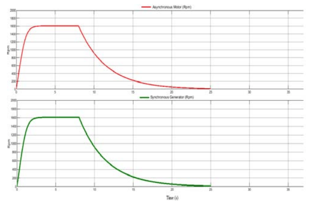
The graphs in Fig 6(a) and Fig 6(b) are showing the relationship between the weights of the flywheel with time. The green and red lines in the graph show that an asynchronous motor and synchronous generator run at synchronous speed. This is because motor, generator, and flywheel are coupling directly without any pulley or belting. The frequency converter controlled the speed of motor.
Fig 6(a) shows the graph with 60cm diameter and 2kg flywheel. After 3 seconds, the speed of the motor and generator is at a stable state. After 8 seconds, the power supply of the motor cut off to OFF mode. At OFF mode, the generator was running with support by the flywheel. With 60cm diameter and 2kg flywheel at 0.178kgm2 inertia will take about 8 seconds to stop the generator. By increasing the weight of the flywheel, the times took for the generator to stop running also increase. With 60cm diameter and 8kg flywheel at inertia 0.356 kgm2, the speed of the motor will stable at 5s and take about 15 seconds to stop the generator after cutting off the power supply.
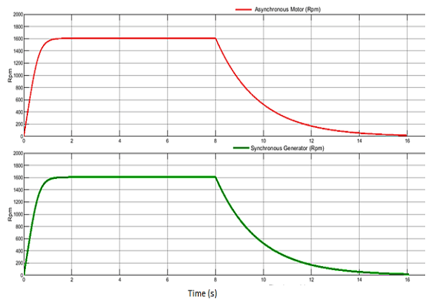
Fig 6(b) shows the graph for flywheel with 60cm diameter and 8kg. The diameter of the flywheel also affects the time of generator stop delay. Since the diameter of the flywheel affects the torque. Increasing in radius will increase the torque. Low mass, higher diameter flywheel is preferred to higher mass low diameter flywheel. This gives better efficiency of the system for given energy storage.
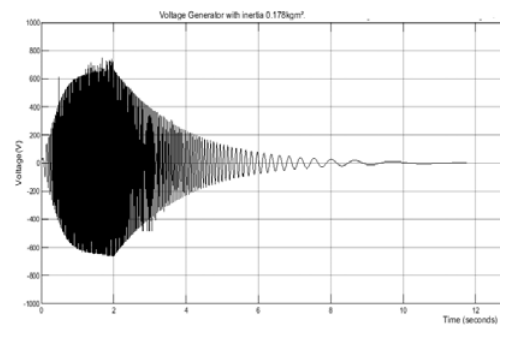
The waveform of output voltage generated by a synchronous generator in Fig 7 shows that the generator still running after the motor OFF mode at time 2s. If the motor and generator were coupling with a 2kg flywheel, the voltage of the generator will decrease slowly in 5 seconds. Initially, the generator takes about 1 second to become stable. When the motor OFF mode at time 2s, the flywheel will make the generator continuously run from time 2s to 7s.
The waveform in Fig 8(a) and Fig 8(b) shows the pattern of generator voltage waveform when the motor is under ON/OFF controlled. The voltage of the generator is in ranges from 1000V to 230V. This range of voltage can fulfill the required voltage of the load. With ON/OFF control in Fig 8(a) with inertia 0.178kgm2, we can see that the output voltage of this synchronous generator still under the voltage range at 240V after two seconds of motor OFF mode. ON/OFF control was applied to the system by active the breaker every two seconds. During OFF mode, the generator was driven by the flywheel. The duration of the generator voltage can sustain was depend on the inertia of the flywheel. Meanwhile, with inertia 0.356 kgm2 can prolong the duration of the generator to stop and the voltage generator at 240V after three seconds motor OFF mode. Fig 8(b) shows the waveform of generator voltage with the inertia of the flywheel at 0.356 kgm2.
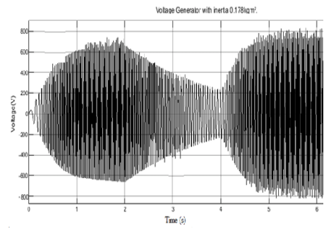
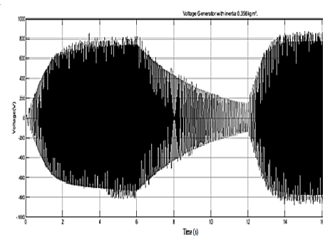
Table 2 shows that the efficiency of the system is very high above 100%. This is because the output power of the system is greater than the input power. Vin is the line voltage of the three-phase supply regulated from 100V to 400V. From this simulation, the highest efficiency of the system is at line voltage 200V achieved at 261% of power efficiency. When increasing the input voltage, the efficiency of the system decreasing from 261% to 108%. This is because the nominal voltage of the generator and motor is the only 400V. If the line voltage is 300V, then the supply voltage of the motor is bigger than 400V. The system becomes unstable when the supply voltage greater than the nominal voltage. The efficiency of the system calculated by using formula:

Table 2. Efficiency of the system
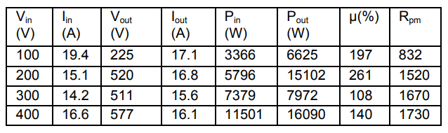
Fig 9 shows that the current of the output generator was stable after half seconds of operation. The output current is about 20A. There is no current spike that occurs at any time of system operation. This is because the asynchronous motor derived the synchronous generator without any jerk or unstable speed. Not like permanent magnet motor, always has jerked during operation will cause a current spike.
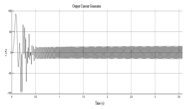
Fig 10 shows that the frequency output voltage of the generator is at a stable state after three seconds of system operation. The frequency is maintained at almost 50Hz. This graph proves that the synchronous generator can provide constant frequency at any load of the system.

Conclusions
The effects of a flywheel on the motor-generator system were investigated. The flywheel in this system makes a reduction in power consumption with an act as energy storage to convert mechanical energy to electrical energy after the power supply off. With ON/OFF control by the frequency inverter, the power consumption will reduce. The load such a heater still can function to maintain the temperature. Besides that, a synchronous generator also provides high efficiency to the system. With 1600rpm, the efficiency of the system achieves 200% with supply voltage 200V. This is possible because this modelling used a low-speed high voltage synchronous generator then give more output power compare with input power. This calculation of power can be referred to the formula 6. Therefore, from this investigation can conclude that the flywheel motor generator system proposed in this study offer higher efficiency which can solve the problem in power consumption issue. In the future, this study will continue with additional element to improve the system with a hybrid flywheel.
Acknowledgment: Universiti Kebangsaan Malaysia for funding the research under Grant Code GGPM-2019-031.
REFERENCES
1. Islam, S.; Ponnambalam, S.G.; Lam, H.L. Energy management strategy for industries integrating small scale waste-to-energy and energy storage system under variable electricity pricing. J. Clean. Prod. 127(2016), 352–362.
2. Sarker, M.R., Mohamed, A., Mohamed, R. Performance evaluation modeling a Microelectromechanical system based Finite Element piezoelectric shear actuated beam. Prz. Elektrotechniczny 2015, 91.
3. Nadaleti, W.C. Utilization of residues from rice parboiling industries in southern Brazil for biogas and hydrogen-syngas generation: Heat, electricity and energy planning. Renew. Energy. 131(2019), 55–72.
4. Sarker, M.R., Mohamed, R. A Batteryless low input voltage micro-scale thermoelectric based energy harvesting interface circuit with 100mV start-up voltage. Prz. Elektrotechniczny 2014, 90.
5. Gilbert, B., Graff Zivin, J. Dynamic salience with intermittent billing: Evidence from smart electricity meters. J. Econ. Behav. Organ. 107(2014), 176–190.
6. Wu, Y.; Bingham, C.M.; Peel, D.J.; Howe, D. Active magnetic bearings for a flywheel peak power buffer for electric vehicles. Int. J. Appl. Electromagn. Mech. 2001, 15, 201–206.
7. Mohamed, R., Sarker, M.R., Mohamed, A. An optimization of rectangular shape piezoelectric energy harvesting cantilever beam for micro devices. Int. J. Appl. Electromagn. Mech. 50(2016), 537–548.
8. Sebastián, R., Peña-Alzola, R. Control and simulation of a flywheel energy storage for a wind diesel power system. Int. J. Electr. Power Energy Syst. 64(2015), 1049–1056.
9. Brühl, J., Smith, G., Visser, M. Simple is good: Redesigning utility bills to reduce complexity and increase understanding. Util. Policy. 60(2019), 100934.
10. Thakre, S.B., Zode, S.H., Singh, A.S., Ingole, S.R. Self Generator Free Energy Flywheel. Int. Res. J. Eng. Technol. 2018, 1062–1065.
11. Zhang, C., Tseng, K.J., Nguyen, T.D., Zhao, G. Stiffness analysis and levitation force control of active magnetic bearing for a partially-self-bearing flywheel system. Int. J. Appl. Electromagn. Mech. 36(2011), 229–242.
12. Hedlund, M., Abrahamsson, J., Pérez-Loya, J.J., Lundin, J., Bernhoff, H. Eddy currents in a passive magnetic axial thrust bearing for a flywheel energy storage system. Int. J. Appl. Electromagn. Mech. 54(2017), 389–404.
13. Nagaya, K., Kanno, K., Hayashi, N. Control of flywheel system with high-Tc superconducting bearings. Int. J. Appl. Electromagn. Mech. 10(1999), 237–247.
14. Jin, Z., Sun, X., Yang, Z., Wang, S., Chen, L., Li, K. A novel four degree-of-freedoms bearingless permanent magnet machine using modified cross feedback control scheme for flywheel energy storage systems. Int. J. Appl. Electromagn. Mech. 60(2019), 379–392.
15. Sarker, M.R., Mohamed, A., Mohamed, R. Implementation of non-controlled rectifier circuit based on vibration utilizing piezoelectric bending generator. Int. J. Appl. Electromagn. Mech. 2017, 54.
16. Soomro, A., Amiryar, M.E., Pullen, K.R., Nankoo, D. Comparison of Performance and Controlling Schemes of Synchronous and Induction Machines Used in Flywheel Energy Storage Systems. Energy Procedia. 151(2018), 100–110.
17. Amiryar, M., Pullen, K., Nankoo, D. Development of a HighFidelity Model for an Electrically Driven Energy Storage Flywheel Suitable for Small Scale Residential Applications. Appl. Sci. 8(2018), 453.
18. Daoud, M.I., Abdel-Khalik, A.S., Massoud, A., Ahmed, S. An asymmetrical six phase induction machine for flywheel energy storage drive systems. In Proceedings of the Proceedings – 2014 International Conference on Electrical Machines, ICEM 2014; Institute of Electrical and Electronics Engineers Inc., 2014; 692–698.
19. Gurumurthy, S.R., Sharma, A., Sarkar, S., Agarwal, V. Apportioning and mitigation of losses in a Flywheel Energy Storage system. In Proceedings of the 2013 4th IEEE International Symposium on Power Electronics for Distributed Generation Systems, PEDG 2013 – Conference Proceedings; IEEE Computer Society, 2013.
20. Çelikel, R., Özdemir, M., Aydoǧmuş, Ö. Implementation of a flywheel energy storage system for space applications. Turkish J. Electr. Eng. Comput. Sci. 25(2017), 1197–1210.
21. Dergachev, P.; Kosterin, A.; Kurbatova, E.; Kurbatov, P. Flywheel energy storage system with magnetic hts suspension and embedded in the flywheel motor-generator. In Proceedings of the Proceedings – 2016 IEEE International Power Electronics and Motion Control Conference, PEMC 2016; Institute of Electrical and Electronics Engineers Inc., 2016; 574–579.
22. Caruso, J.F.; Coday, M.A.; Davidson, M.E.; Riner, R.D.; Borgsmiller, J.A.; Olson, N.M.; Taylor, S.T.; McLagan, J.R. The effect of flywheel-based resistive exercise workouts on testosterone/cortisol ratios. Isokinet. Exerc. Sci. 20(2012), 51–60.
Authors: M.S. ALI is a PhD student at the Department of Electrical, Electronic and Systems Engineering, Universiti Kebangsaan Malaysia (UKM), E-mail: mohdshamsul@gmi.edu.my
Dr. Mahidur R. Sarker is currently working as Research Fellow to the Institute of IR 4.0, Universiti Kebangsaan Malaysia (UKM). Email:mahidursarker@ukm.edu.my.
Dr. Ahmad Asrul Ibrahim is currently working as Senior Lecturer of Department of Electrical, Electronic and Systems Engineering, Universiti Kebangsaan Malaysia (UKM), E-mail: ahmadasrul@ukm.edu.my.
Dr. Ramizi Mohamed is an associate professor of Department of Electrical, Electronic and Systems Engineering, Universiti Kebangsaan Malaysia (UKM), E-mail: ramizi@ukm.my.
Source & Publisher Item Identifier: PRZEGLĄD ELEKTROTECHNICZNY, ISSN 0033-2097, R. 97 NR 11/2021. doi:10.15199/48.2021.11.34
