Published by Yanbo CHE, Jian CHEN,
School of Electrical Engineering & Automation, Tianjin University, Tianjin China.
Abstract. Microgrid system has received more and more attention internationally in recent years. As the most effective form of distributed generations, microgrid system has also found wide applications in many areas. In this paper, the optimal configuration issue of microgrid system is described briefly first. And then the monitoring system of microgrid system is discussed in details. Different control methods of microgrid system and their advantages and shortcomings are analyzed later. The comparative analysis of different control methods is carried out. Finally, a laboratory-scale microgrid system is proposed as an example to verify the microgrid control strategy. The operation experimental results show that the laboratory-scale microgrid system can operate in grid-connected or islanded mode, with a seamless transfer from one mode to the other, and hence increase the reliability of energy supplies. The study can be used to guide the research of microgrid systems.
Streszczenie. Zaprezentowano różne rozwiązania sieci typu microgrid. Zaproponowano metody sterowania i kontroli systemem, metody optymalizacji konfiguracji oraz systemy monitoringu. (Analiza projektowania i sterowania sieciami typu microgrid)
Keywords: microgrid, optimal configuration, monitoring system, control strategy
Słowa kluczowe: microgrid, systemy monitoring, konfiguracja sieci.
Introduction
In recent years, distributed generation (DG) technologies such as photovoltaic (PV), wind turbine (WT), combined cooling heating and power (CCHP), and fuel cells have received wide interest due to the benefits such as high reliability, good quality power supply, environmental preservation, and energy cost reduction [1]. However, increasing amounts of individual distributed generators will also cause as many problems as it may solve [2, 3]. A large number of distributed generators will probably introduce difficulties of control and manage. A better way to realize the emerging potential of distributed generation is to treat generation and associated loads as a system [4]. In order to solve the contradiction between power system and distributed generation and improve the operation performance of power system, microgrid technology comes into being. Microgrid can operate in grid-connected mode or islanded mode and hence increase the reliability of energy supplies by disconnecting from the grid in the case of network faults. Microgrid is the most effective form of distributed generations.
Nowadays, a considerable research has been undertaken on the microgrid technology. As part of the research, a series of microgrid test facilities, such as CERTS microgrid test bed, GE microgrid in America [5, 6], Aichi, Kyoto, Sendai microgrid in Japan [7, 8], Labein, Kythnos, CESI microgrid in Europe [9, 10], have been built for possible demonstrations of advanced distributed generation system. But as a newly-emerged thing, the practical applications of the microgrid is still in the initial stage, and further research is still necessary. Design and control issues are the key points which decide the performance of microgrid system. How to design the configuration and control method of microgirdr systems rationally and effectively is the most important one to be solved among relevant issues.
This paper discusses optimal configuration, monitoring system and introduces control strategy of microgrid system. A case study is given to introduce and discuss. Conclusion is stated in the last part.
Microgrid design
1 Optimal configuration
As shown in fig. 1, microgrid system typically includes PV, WT, energy storage systems, diesel generator, loads, and other distributed generations. In order to fulfill the target of economical and optimal operation of systems, the optimal capacity configuration of components is very important in system design. In related researches, scholars have made great efforts to study the problems of optimal configuration of systems. The optimal capacity configuration is summarized in [11] briefly. The authors of [12] made the optimal design adopting the method of genetic algorithm. In [13] the simulation software HOMER is used to analyze the systems.

HOMER is designed to analyze the configuration of renewable power systems. And it can simulate grid-connected and off-grid microgrid systems. HOMER compares different designs based on technical and economic characteristics in research of the optimal solution. At the same time, it can help analyze the effects brought by uncertainty and changes of input data, such as renewable energy generation installed capacity, diesel generator capacity, energy storage system capacity and resource data. The microgrid system model in HOMER is shown in fig. 2.

2 Monitoring system
Microgrid system consists of renewable energy generation systems (such as wind, solar, biomass, and so on), clean energy generation systems (fuel cells, micro gas turbines, and so on), energy storage systems, and a variety of loads. It is characterized by containing a variety of distributed energy. In view of the above characteristics, microgrid monitoring system must match the following main tasks and requirements:
(1) In order to monitor each generation unit simultaneously and improve the reliability and operational efficiency of microgrid system, monitoring system should use distributed structure so that it can monitor the operating parameter comprehensively.
(2) It should support a variety of communication protocols so that it can communicate with distribution terminal device, includes receiving and handling parameters of analog or digital in different formats.
(3) The system configuration, subsystem configuration, the device configuration, the task configuration can all be defined and modified online.
(4) The operation of the whole system, each subsystem and each device in system can all be monitored and remote controlled.
(5) The historical operation data of microgrid system is the most significant data which can be used to make accurate prediction of system state and promote the operation and control of the microgrid system. Therefore, the monitor system must be able to record and long-term storage the operating data of microgrid system. In addition, the data can also be used for accident analysis, statistical analysis, calculation and future planning [14].
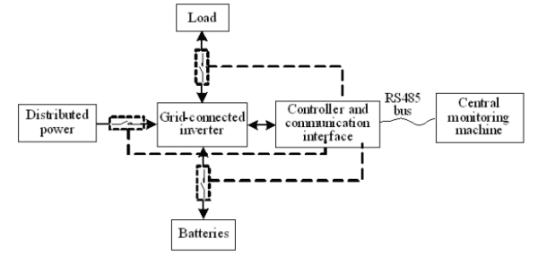
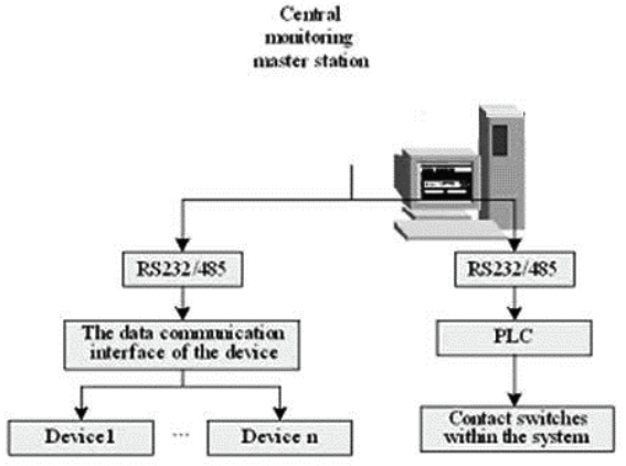
The monitoring system of micro-network system makes the distributed generation as sub-unit monitoring, the equipment of subsystem as the monitoring device. Using the communication between serial port and various devices to achieve the acquisition of real-time operational data, the detection of switch status, and remote monitoring equipment. Monitoring subsystem topology is showed in fig.3 The inverter is the core of monitoring subsystem because grid-connected inverter is the heart of all distributed generation units and stores almost all of the running data. For data acquisition and remote monitoring are achieved through the controller and communication interface. The structure of monitoring system is shown in fig. 4. Specific programs and control process are set by the controlled system.
Microgrid control
Compared with traditional large-capacity thermal power, there are volatility in primary energy (such as wind and solar) and bidirectional flow in dynamic allocation of secondary energy (such as bidirectional energy flow between microgrid and large power grid, bidirectional energy flow in the bus of energy storage units) in microgrid. In addition, the load following reaction speed of each DG unit is very different. All these features add the complexity of microgrid automatic management, especially the optimal scheduling [15].
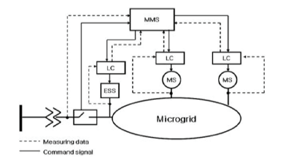
The microgrid system often has a hierarchical control structure, as shown in fig.5. There are two control layers: MMS and local controller (LC).The MMS is a centralized controller that deals with management functions, such as disconnection and resynchronization of the microgrid and the load-shedding process. In addition to this function, the MMS is responsible for the supervisory control of microsources and the ESS. Using collected local information, the MMS generates a power output set point and provides it to the LCs. An LC is a local controller that is located at each microsource and controls the power output according to the power output set point from the MMS [16]. The hierarchical control structure contributes to the control performance of microgrid.
Besides the control structure, control methods are the research core of microgrid. The volatility of distributed generation and the differences of distributed generation units have increased the complexity and difficulty of microgrid control. Distributed generations in microgrid are connected with the busbar through power electronic devices that are very different from the generators that connected directly with the grid. In addition, energy storage systems are usually equipped to increase the system inertia. So the traditional control methods are no longer applied properly in microgrid operation control.
At present, there are mainly two control methods, master-slave control and peer-to-peer control [17]. There is a main control unit in master-slave control to maintain the constant voltage and frequency. The main control unit adopts V/F control while other distributed generations adopt PQ control to output certain active and reactive power. Each unit is equal in peer-to-peer control. Peer-to-peer control is based on the method of external characteristics of declining. It associates frequency versus active power, voltage versus reactive power respectively. Through a certain control algorithm, the voltage and frequency will be adjusted automatically without the help of communication.
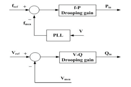
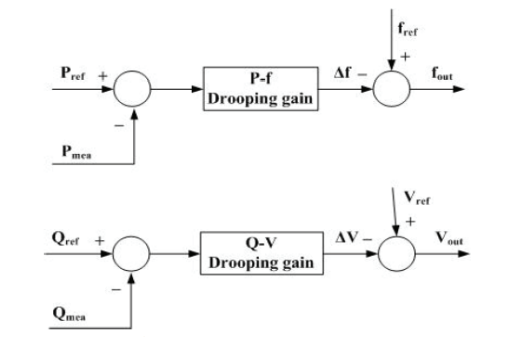
The control method based on drooping characteristics is widely used in peer-to-peer control. One is f-P and V-Q control which produce reference active and reactive power of distributed generations by measuring the system frequency and amplitude of output voltage of distributed generations. As shown in fig.6. The other is P-F and Q-V control which produce the frequency and amplitude of output voltage by measuring the active and reactive power of distributed generations. As shown in fig.7.
Master-slave control and peer-to-peer control each has advantages and disadvantages. They are suitable for different operation. At present, the built experimental systems commonly adopt master-slave control in China. Compared with master-slave control, peer-to-peer control has certain advantages but its application needs further study.
Case study
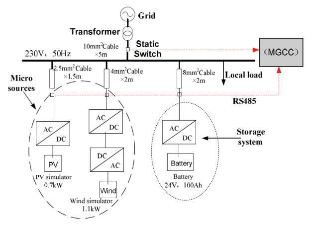
The structure of the microgrid (MG) system is shown in fig. 8. It is a single phase system, with 230V, 50Hz, comprising PV simulator, wind simulator and battery storage [18]. Both of them are connected to the AC grid via flexible power electronic interface [19]. Also there is a Microgrid Central Controller (MGCC) which is responsible for the optimization of the microgrid operation.
The MGCC functions range from monitoring the actual active and reactive power of the distributed resources, voltage and frequency of the AC bus. Also it is responsible for the maximization of the microgrid’s value and the optimization of its operation by sending control signal settings to the distributed resources and controllable loads via communication lines [20]. In this paper, RS485 communication lines are used to realize this function.
For the laboratory-scale MG, based on the control strategies of the micro sources and the battery energy storage, a series of experiments were carried out, the power output of the distributed generators and battery, voltage and frequency of the AC bus were real-time measured and analyzed by the Power Quality Analyzer.
A. Transfer from islanded mode to grid-connected mode While switching from islanded mode to grid-connected mode, the voltage and frequency should be maintained within acceptable limits. The dynamic response process is shown in fig. 9. At t3, the MG is synchronized to the grid and its voltage and frequency become equal to the values of the network. The PV simulator and wind simulator maintain constant power output and the battery will be charged by the grid. As shown in fig.9, the voltage and frequency will fluctuate accordingly with the grid.
B. Transfer from grid-connected mode to islanded mode Also the voltage and frequency should be maintained within acceptable limits when switching from grid-connected mode to Islanded mode. The dynamic response process is shown in Fig. 10.
At t4, the MG is disconnected from the grid and returns to Islanded mode operation. During this transition, the voltage and frequency will decrease slightly. For the safe operation, the distributed generators will disconnect from the MG (the output power become zero), the battery will increase its power output accordingly for the power balance of the system. Due to the voltage/frequency control of the battery inverter, the voltage and frequency of the MG are restored to the nominal value. Then at t5, the distributed generators will connect to the MG again and return to its initial operating state. From the voltage and frequency behaviors in Fig. 9 and Fig. 10, it may be observed that MG stability is not lost when facing transition between Grid-connected mode and Islanded mode.
Conclusion
In this paper, discussion and analysis of microgrid design and control are carried out. And the design method of HOMER is introduced briefly. The monitoring system design of microgrid is described in details. The control methods of microgrid system are mainly demonstrated. The master-slave control and peer-to-peer control are analyzed in detail. A laboratory-scale MG system has been set up. The operation experimental results show that the laboratory-scale MG system can operate in grid-connected mode or islanded mode and hence increase the reliability of energy supplies, with a seamless transfer from the one mode to the other.
Acknowledgment
This work is supported by National Key Foundational Research Project ‘Distributed Generation Supply System Pertinent Foundational Research’ (No.2009CB219700)
REFERENCES
[1] Jian W., Xing-yuan L., Xiao-yan Q., Power System Research on Distributed Generation Penetration, Automation of Electric Power Systems, vol. 29(24), pp. 90-97, 2005.
[2] A.M. Azmy and I. Erlich, “Impact of distributed generation on the stability of electrical power system,” Power Engineering Society General Meeting, vol. 2, pp.1056-1063, 2005
[3] J.G. Slootweg and W.L. Kling, “Impacts of distributed generation on power system transient stability,” Power Engineering Society Summer Meeting, vol.2, pp.862-867, 2002
[4] R. Lasseter, A. Akhil, C. Marnay and J. Stephens et al, “White Paper on Integration of Distributed Energy Resources. The CERTS Microgrid Concept,” Consortium for Electric Reliability Technology Solutions (CERTS), CA, Tech. Rep. LBNL-50 829, 2002.
[5] R.H. Lasseter and P. Piagi, “Control and Design of Microgrid Components, Final project report,” PSERC publication 06-03, [Online]. Available: http://certs.aeptechlab.com/
[6] US Department of Energy Electricity Distribution Programme, Advanced Distribution Technologies and Operating Concepts – Microgrids, [Online]. Available: http:// http://www.electricdistribution. ctc .com/Microgrids .htm
[7] Toshihisa Funabashi and Ryuichi Yokoyama, “Microgrid Field Test Experiences in Japan,” Power Engineering Society General Meeting, pp. 1-2, 2006
[8] S. Morozumi, “Micro-grid demonstration projects in Japan,”IEEE Power Conversion Conference, pp.635 642, April, 2007.
[9] Oleg Osika, Aris Dimeas and Mike Barnes et al, “DH1_Description of the laboratory micro grids,” Tech. Rep. Deliverable DH1, 2005
[10] European Research Project More Microgrids. [Online]. Available: http://Microgrids.power.ece.ntua.gr
[11] J. Chen, Y. B. Che, and J. J. Zhang, “Optimal configuration and analysis of isolated renewable power systems.” Power Electronics Systems and Applications (PESA), 2011 4th International Conference on pp. 1284-1292.
[12] Eftichios Koutroulis, Dionissia Kolokotsa,Antonis Potirakis, Kostas Kalaitzakis. Methodology for optimal sizing of standalone PV–Wind. Solar Energy,2006(80): 1072-1088.
[13] S.M. Shaahid, M.A. Elhadidy. Economic analysis of hybrid PV-diesel-battery power systems for residential loads in hot regions. Renewable and Sustainable Energy Reviews,2008(12): 488-503.
[14] J. D. Ren, Y. B. Che, and L. H. Zhao, “Discussion on monitoring scheme of distributed generation and micro-grid system,” Power Electronics Systems and Applications (PESA), 2011 4th International Conference on, pp. 1-6.
[15] Y. B. Che, and J. Chen, ”Control research on microgrid systems based on distributed generation,” Applied Mechanics and Materials, vols. 58-60 (2011), pp. 417-422.
[16] Jong-Yul Kim, Jin-Hong Jeon, Seul-Ki Kim, Changhee Cho, June Ho Park, Hak-Man Kim, and Kee-Young Nam: Cooperative Control Strategy of Energy Storage System and Microsources for Stabilizing the Microgrid during Islanded Operation. IEEE Trans. Power Electron. Vol. 25 (2010), p. 3037-3048
[17] Yang Zhangang, Wang Chengshan, Che Yanbo: A Small-scale Microgrid System with Flexible Modes of Operation. Automation of Electric Power Systems. Vol. 33 (2009), p. 89-92
[18] Y. B. Che, Z. G. Yang, and K. W. E Cheng, “D. Construction, operation and control of a laboratory-scale microgrid,” Power Electronics Systems and Applications, PESA 2009. 3rd International Conference on, pp. 1-5.
[19] D. Georgakis, S. Papathanassiou and N. Hatziargyriou, “Operation of a prototype Microgrid system based on microsources,” Power Electronics Specialists Conference, pp. 2521- 2526, 2004
[20] D. Nikos Hatziargyriou et al, “DC1_Microgrid Central Controller strategies and algorithms,” Tech. Rep. Deliverable DC1, 2004
Authors: Yanbo CHE: Associate professor in school of electrical engineering and automatic, Tianjin University, E-mail: ybche@tju.edu.cn
Jian CHEN: PHD student in school of electrical engineering and automatic, Tianjin University, E-mail: happy_chenjian@163.com.
Source & Publisher Item Identifier: PRZEGLĄD ELEKTROTECHNICZNY (Electrical Review), ISSN 0033-2097, R. 88 NR 5b/2012
