Published by Electrotek Concepts, Inc., PQSoft Case Study: Evaluation of Harmonic Impacts from Compact Fluorescent Lights On Distribution Systems, Document ID: PQS0322, Date: April 16, 2003.
Abstract: This case study presents the results of a research investigation into the impact of compact fluorescent lights (CFLs) on an existing distribution system. The analysis uses a combination of EMTP simulations and conventional harmonic analysis simulations (SuperHarm) to predict the distribution system distortion levels as a function of system characteristics and CFL penetration levels. Compact fluorescent light characteristics from measurements and distribution system data collected are utilized to develop simulation models.
This case study is summarized from a paper presented at PQA 1994 by Rory Dwyer and Afroz K. Khan, from Electrotek Concepts, and Robert K. McCluskey, Roger Sung, and Thomas Houy, from Southern California Edison.
INTRODUCTION
Compact fluorescent lights (CFLs) provide significant energy savings over incandescent lighting. As a result, CFLs are being promoted as part of energy conservation programs at many electric utilities. A recent study performed by Worcester Polytechnic Institute (Emanuel, 1992) estimated the impact of these lights on distribution system voltage distortion levels. The results indicated that relatively low CFL penetration levels could cause the feeder voltage distortion to exceed 5%.
A number of questions associated with the models used in the Worcester Polytechnic Institute study need to be addressed. For instance, only the feeder of interest was modeled while other feeders supplied from the same bus, with their loads and capacitors, were not included in the model. The effect of the load characteristics on system resonance conditions is also a question. These concerns are explored in the following research investigation.
COMPACT FLUORESCENT CHARACTERISTICS
Measurements were performed for a wide variety of CFLs. These tests evaluated the harmonic characteristics of each lamp. This resulted in three general categories of CFLs:
1. High distortion electronic ballast CFLs. These typically have current distortion levels exceeding 100%.
2. Low distortion electronic ballast CFLs. These have distortion levels typically below 30% based on using some type of harmonic control technology in the ballast, such as series filters.
3. Magnetic ballast CFLs. These have distortion levels below 20% based on the characteristics of the lamp in series with a ballast inductance.
DESCRIPTION OF DISTRIBUTION SYSTEM STUDIED
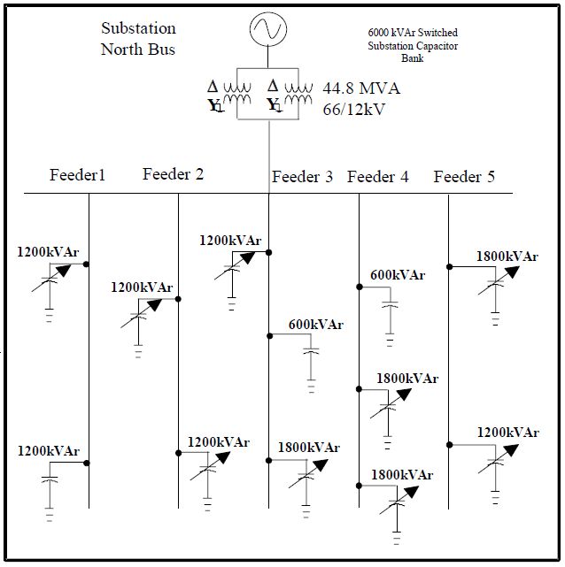
A simplified one line representation of the system studied can be seen in Figure 1. This system consists of six parallel feeders serviced by a 44.8 MVA substation transformer with a substation capacitor bank of 6000 kVAr. The primary feeder modeled for this study is the Feeder 1 12/6.9kV circuit. Approximately 31% of the loads on this feeder are commercial. These commercial loads are serviced line to line. The residential loads are serviced line-to-line overhead and either line-to-line or line-to-neutral underground.
FREQUENCY RESPONSE CHARACTERISTICS
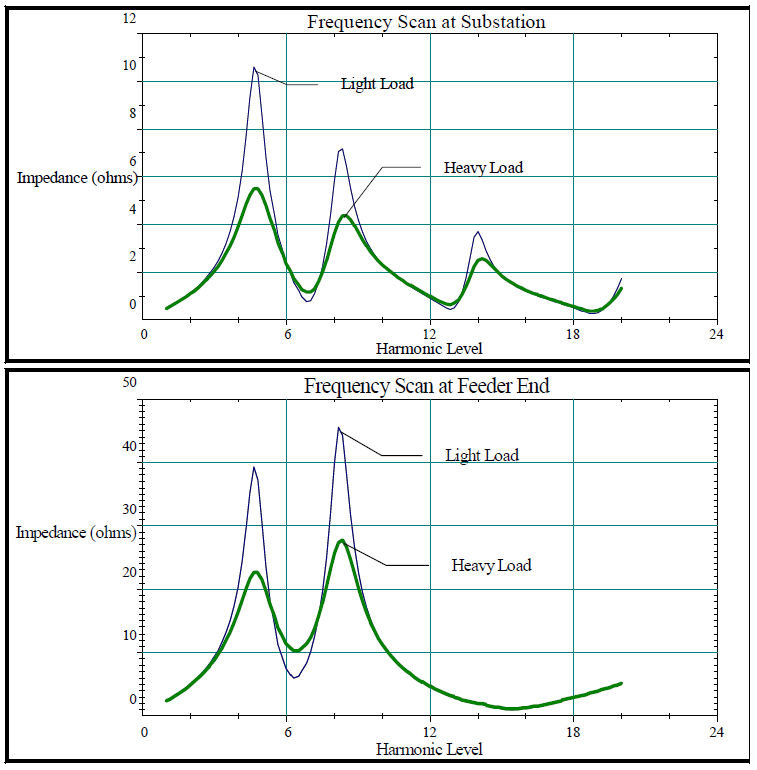
The distribution system frequency response characteristics determine the impact of the harmonic currents on the system voltage distortion. The frequency response is determined by the system strength, the capacitors in service, and the amount of load (damping). Several key configurations were investigated. Figure 2 illustrates the frequency response characteristics with the substation capacitor bank incorporated along with some of the banks on the parallel feeders. The substation capacitor bank moves the primary system resonant peak to reach the 5th harmonic. In relation to the other scans performed, this case appears to be the worst situation regarding undesirable high 5th harmonic impedances. This scenario will be utilized as the basis for evaluating CFL penetration impacts.
One important effect that needs to be considered is the load characteristics, especially when the load includes a significant amount of power electronics equipment (power supplies). The load characteristics utilized in the previous section consist of basically resistive load to include the damping effect on system resonances. A resistive representation is not accurate for most nonlinear loads.
EMTP Simulations
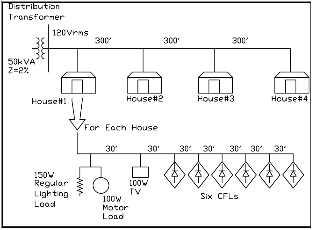
Simulations from the Electromagnetic Transients Program (EMTP) are used to develop approximate models that can be used in the frequency domain simulations to evaluate the impact of these loads on the overall system frequency response characteristics. The EMTP model was developed to obtain a benchmark comparison for a residential circuit example. The circuit shown in Figure 3 was used to represent a single distribution transformer supplying four residences. Each residence is assumed to have six 25 W CFLs. Typical impedances are used to represent the household wiring and the cabling between the residences. Other loads are also included for the residences: 100 W electronic load (TV), 150 W incandescent lighting, and 100 W refrigerator load.
Effect on System Frequency Response
To obtain the frequency response characteristics for the impact of non-linear loads on the system, the parameters obtained from the EMTP simulations for load characterization were incorporated into the existing frequency scan model. Figure 4 illustrates the resulting characteristics at mid-feeder.
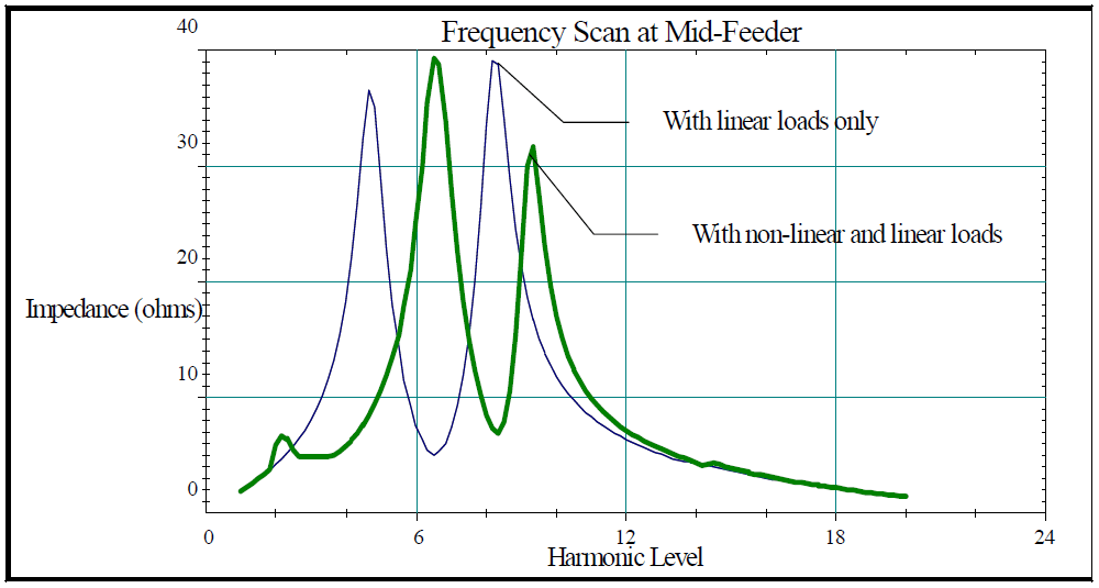
The figure above provides a comparison of the light loading frequency response characteristics with linear loads and with both linear and non-linear loads. As expected, the frequency scan with the addition of non-linear loads shifts the resonance points to the right with a slight additional harmonic resonance around the 2nd harmonic. The addition of the non-linear load characteristics, derived from EMTP simulations, results in a filter effect at the lower frequencies. It can be seen that the high impedance, previously observed at the 5th harmonic, has been radically reduced. This effect results in the increase of the impedance at the 7th harmonic.
EVALUATION OF EXPECTED HARMONIC DISTORTION LEVELS
Base Case Distortion Levels
The least favorable feeder capacitor configuration was used to calculate harmonic levels due to nonlinear loads currently existing in the system with the exclusion of CFLs. The impedance scan of Figure 2 indicates that this configuration results in a peak resonance at or near the fifth harmonic. Voltage THD levels resulting from this “unfavorable” capacitor configuration are shown in Figure 5 and subsequent figures as horizontal lines.
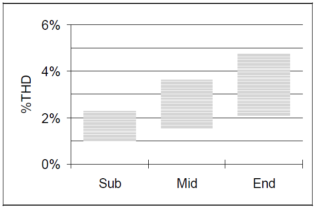
THD levels are shown in Figure 5 for three locations along Feeder 1: near the substation, mid-feeder, and at the feeder end. A range of values is shown for each location to illustrate the effect of feeder loading. As load approaches its minimum (which corresponds to 50% of the peak load reported by SCE), linear load tends to decrease more rapidly than harmonic load. The result is that voltage THD is highest at minimum load. Assuming a maximum allowable voltage THD of 5%, as suggested by IEEE Standard 519-1992, Figure 5 shows that harmonic distortion should not be a problem on the system, regardless of feeder loading or capacitor configuration.
Effect of CFL Penetration vs. Voltage Distortion
Distortion levels due to CFL penetrations of 50 W, 100 W, and 150 W per household are shown in Figure 6. Voltage THD values can be very high – up to 16% for the case of maximum CFL penetration, unfavorable capacitor configuration, and minimum feeder loading. This is a very conservative estimate, for it assumes that all CFLs in the system use the high current THD electronic ballasts mentioned earlier. Another factor contributing to the high distortion levels simulated for this case is that damping due to CFLs and other electronic loads is represented in this model by simple parallel RL branches, rather than by the more accurate RLC representation developed. This was done because past research efforts on the effects of CFLs have assumed simple RL damping. The WPI study made this assumption and concluded that CFL penetrations of as little as 200 kW per feeder could cause unacceptable voltage distortion. Relying upon the same assumption for the Feeder 1 study resulted in a similar conclusion, as Figure 6 indicates. Figure 8 shows how much the RL damping model overestimates harmonic levels on the feeder.
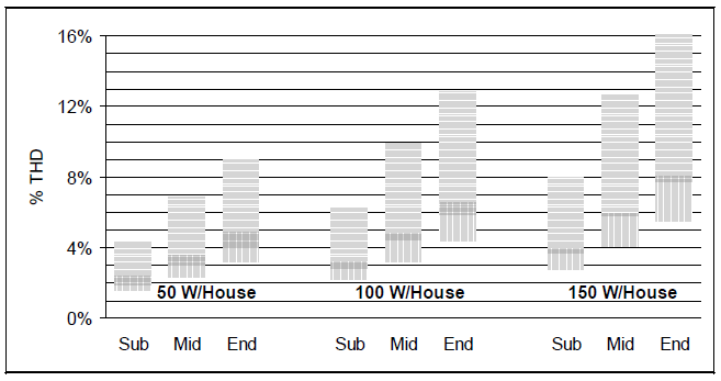
Figure 6 also illustrates the dramatic effect that feeder capacitor configuration can have on harmonic distortion. The vertical line portion of the bar graph indicates a “favorable” capacitor configuration – all capacitors in the circuit in service. With all banks switched on, the parallel resonance is shifted upward away from the fifth harmonic. The resulting voltage THD levels are approximately 50% of the corresponding levels with a fifth harmonic resonance (horizontal lines).
Effect of CFL Type
CFL harmonic injection characteristics are an important effect to consider. System distortion levels are dramatically reduced when low current THD electronic ballast or magnetic ballast CFLs are employed. Figure 7 shows that if these types of CFLs are used throughout the system, feeder voltage THD levels can be expected to remain at or below 5%, regardless of system loading, capacitor configuration, and CFL penetration (150 W per household is assumed in the figure).

Effect of Electronic Power Supply Damping Model
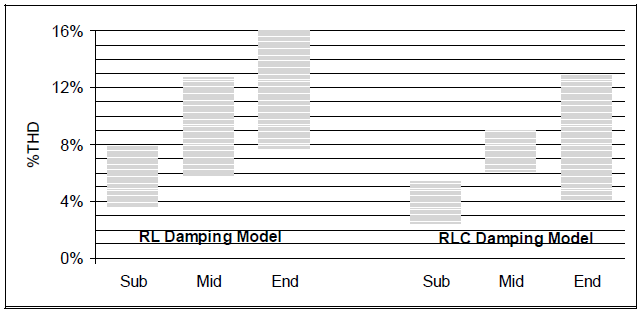
The final case considered is the effect of the damping model assumed for electronic loads. Figure 8 compares the worst case of Figure 6 (150 W CFL per household) with the same case using the RLC damping model. The result is a 20-30% reduction in THD levels. Significant as it is, the drop in distortion is understated, because it assumed that all residential transformers are connected line-to-neutral. However, because the majority of transformers are in fact line-to-line, the amount of ninth harmonic current injected into the system is overstated in this case.
CONCLUSIONS
The conclusions from these simulations are generally in agreement with the conclusions of previous studies performed by WPI. However, the new work, illustrating the important effect of the load models, indicates that the actual distortion levels that can be expected are not as severe as predicted in previous studies. SCE is not presently experiencing any significant harmonic problems with CFLs in use by customers; however, results of this modeling study indicate that further investigation into high- distortion-level CFL effects may be warranted. The distortion levels that can be expected are very dependent on system conditions. Capacitor configurations will cause system resonances that can magnify specific harmonic components. Because similar modeling results could apply to penetration of ASDs in heat pumps and electric vehicle battery chargers, these loads may also warrant further investigation and should be modeled separately due to their different operating characteristics.
REFERENCES
[1] A. E. Emanuel, T. J. Gentile, D. J. Pileggi, E. M. Gulachenski, C. E. Root, “The Effect of Modern Compact Fluorescent Lights on Voltage Distortion”, IEEE/PES 1992 Summer Meeting.
[2] R. Zavadil, M.F. McGranaghan, G. Hensley, K. Johnson, “Analysis of Harmonic Distortion levels in Commercial Buildings”, First International Conference on Power Quality: End-Use Applications and Perspectives, 1991, B-24, pp. 87-92.
[3] W. M. Grady, A. H. Chaudry, A. Mansoor, and M.J. Samotyj “An Investigation of Harmonics Attenuation and Diversity among Distributed Single-Phase Power Electronic Load”, Transmission and Distribution Conference 1994, pp. 110-116.
RELATED STANDARDS
IEEE Standard 519
GLOSSARY AND ACRONYMS
CFL: Compact Fluorescent Light
EMTP: Electromagnetic Transients Program
THD: Total Harmonic Distortion
