Published by Petre Lucian OGRUTAN1, Lia Elena ACIU1, Dan LOZNEANU1, Ioan ROSCA2,
Transilvania University of Brasov, Romania (1), Transilvania Sud Electricity Distribution (2)
Abstract. Protection devices against over-voltage and over-currents for low voltage systems are equipped with varistors and gas-discharge tubes around a fuse, having a disconnection time about 200ms. This paper proposes an intelligent protection system that includes a real-time energy distribution monitoring system for the consumer, providing rapid load disconnection/reconnection without any human intervention, which is considered as an important improvement.
Streszczenie. Urządzenia chroniące przed przepięciami i przetężeniami w instalacji elektrycznej zawierają warystory, iskierniki oraz bezpieczniki o czasach działania około 200 ms. W artykule przedstawiono inteligentny rozwiązanie ochrony zawierające system monitorowania użytkownika energii w czasie rzeczywistym oraz zapewniające szybkie wyłączenie/załączenie bez ingerencji człowieka (Zastosowanie urządzeń wykorzystujących mikrokontrolery do ochrony i monitorowania instalacji elektrycznej)
Keywords: safety, microcontroller, monitoring, low voltage, distribution systems
Słowa kluczowe: bezpieczeństwo, mikrokontroler, monitorowanie, instalacja elektryczne
Introduction
A recent study achieved for the European Community [1] was aimed at investigating the causes of accidental fires in order to establish effective safety provisions for low voltage consumers against such hazards. The study mentions, for instance, a percentage of 31% of fires caused by the electric section of the equipments. Within this context, ascertains that most of the fires were caused by the defects in the electrical system – shortcircuits and overvoltages. Consequently there is a worldwide concern for identifying and applying new methods of protection.
The levels of the overvoltages occurring in electrical supply systems are lower than those arising in electrical power transport and distribution systems yet under unfavorable conditions the former can also cause significant equipment damage. A situation specific to low voltage systems is the occurrence of hazardous accidental voltages at the grounding connections of the equipments due to the effects of the carried overcurrents. Under the present conditions of operation of the energy market and due to the increased requirements in terms of the quality of services imposed on electrical energy providers, the need to determine the level of overvoltages becomes increasingly important in distribution and supply systems as well. This provides the opportunity to identify the areas of increased electrocution risk, as well as other potentially hazardous situations to consumers in the investigated low voltage systems. Also, the possibility of hazards due to damages produced in low voltage cable systems cannot be neglected.
The computer-assisted simulation of the transient electromagnetic regimes and sequences of such regimes is the only feasible method for performing parametric analyses at the level of accidental voltages, overvoltages and overcurrents in the system. Such parametric analyses allow for determining the level of voltages and currents circulation in any point of the system on a given range of its operating parameters. This is virtually the only solution to anticipate the sensitive areas of potential risk.
Knowing the current values in any point of the system allows an adequate planning of the preventive maintenance of grounding connections, of protection systems and points with damaged insulation, especially in cable systems.
Knowing the voltage values in any point of the system allows to avoid operation at voltage values that are unacceptable not only to consumers but also to certain system components for a prolonged operation regime, knowing the touch and step voltages in all ground connections of the analyzed system for any operating mode including anomalous situations like broken neutral wires or potential equalization conductors.
The measures that can be implemented as following to the performed analyses will produce immediate effects in terms of avoiding unwanted events with respect to electrical safety, reduction of frequency and duration of electrical power outages with the associated technological and economic advantages. Adequate planning of maintenance activities, which follows as a consequence to such analyses, results in enhanced services quality of the provided electrical power. The EMTP-ATP simulation program allows to determine the voltage and current variations occurring in different points of an electrical network, highlighting those locations where an intervention appears necessary by using types of protection devices as proposed in this paper [2]. A single electronic device including embedded systems for overcurrent, overvoltage and user protection against electrocution represents a necessity at this level of modernization [3]. The data exchange with the exterior moves the fuse system into the 21st century by ensuring the facilities for remote control [4]. E.g. a quick and safe fuse which operates at a precise value of the short-circuit current could improve the quality of electrical power by reducing the voltage sags in the system. The paper presents a system for consumer protection against short-circuits and overvoltages that can occur in the low voltage power supply grid. The proposed system was subjected to practical tests for various power factors.
Presentation of the protection device
The protection device proposed in this paper operates as an electronic circuit breaker based on a microcontroller which provides the possibility of transferring distant events into an event log. Its structure is shown in Fig. 1. The proposed device has the following advantages:
-High cut-off speed (maximum 10ms) which is faster than with conventional methods;
-Does not require human intervention since after power cutoff in the case of short-circuit or overvoltage, the power supply is automatically restored (for short-circuits only after eliminating the cause);
-Due to its two-stage action for the case of occurrence of low-value overvoltages or overcurrents, the average voltage value is subtracted thus preventing the load to be cut-off from the supply. This advantage can be obtained for the triac equipped version only;
-The load is cut-off at voltage/current zero-crossing which reduces the perturbations;
-The communication interface to the Internet enables online transfer of electrical power consumer information.
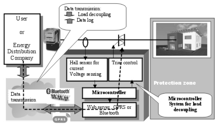
The acquired data including voltage and current values can be transmitted over distance and made available to the interested parties (consumer or electrical power distributor). The necessary condition for data communication is bidirectionality, namely to provide the possibility to remotely control the device by either the client (consumer) or the electrical power distributor. This feature could be useful if the distributor schedules electrical works that could involve potential risks to the consumer (client), by providing the possibility of disconnecting the client over the repair period. The data transmission can be achieved:
-using Bluetooth if there is no GSM coverage or cable Internet is unavailable. The consumer (client) can view the event report on a computer with Bluetooth interface while the representative from the distribution company has direct access with a notebook from the exterior;
-Over GSM modem, while communication is assured over SMS or GPRS if there is GSM coverage, which is the preferred solution in most cases;
-Over the INTERNET, with a web server-like device which collects the data from the microcontroller and posts them on a website.
The relay-based command is more straightforward but the microcontroller must nevertheless detect the zero voltage/current crossings since coupling and decoupling the load must occur during zero crossing in order to protect the relay contacts. Another problem associated to this solution is the relatively high cost involved by a relay capable to withstand high voltages and currents. While it is a simple task to command a load using a relay, the command with solid-state devices is more complicated. Next, is given a brief description of consumer command using triacs and thyristors, which is the usual command method. Mains voltage control applications involve some particular difficulties:
-High currents and voltages, which requires a special attention and safety measures such as optical decoupling, grounding potential management, galvanic isolation of the oscilloscope, etc;
-Especially for transient regimes, the controlled process is usually more complex;
-The need for developing industry applications leads to cost restrictions, requires higher reliability, compliance to EMC standards, etc.
For the microcontroller command variant it is recommendable to use galvanic decoupling between the digital control circuit and the triac, that is, from the mains supply section [3]. The isolation can be achieved through transformers, optocouplers or opto-triacs that assures a turn-on current flowing in the same direction as the main current to provide an optimum command of the triac. The current through the opto-triac is obtained by dividing the main current through the triac, thus assuring that the triac’s turn-on current has the same direction as the main current. The analysis of the voltage and drawn current is achieved by the microcontroller through the embedded A/D converter. The current is analyzed using a dedicated current transducer (Hall) while voltage analysis is performed through rectification, filtering and division. Whenever a short-circuit or a voltage surge occurs, the microcontroller stops sending turn-on pulses to the triac or cuts off the relay command current so that the consumer’s power supply is cut off as well.
For the triac command variant the protection method was devised as a two-stage process. If overvoltages or overcurrents are detected these are can be classified into:
-Non-hazardous (+/- 3%), requiring no countermeasures;
-Less hazardous (+/-10%), which requires modification of the triac’s firing angle. Depending on the magnitude of the over-voltage and over-current, a timer is programmed which determines the turn-on delay of the triac (the control angle). This command reduces the average load voltage and so compensates the voltage or current increase;
-Hazardous (over10%), blocks the gating pulses to the triac thus disconnecting the load from the mains supply. The voltage is continuously measured and after returning to normal values the load is reconnected to the supply system. When short-circuit is detected, the supply is re connected after a delay period and if the short-circuit persists the triac is blocked for another interval of time.
The condition of over-voltage or over-current is evaluated over one period of the supply voltage by verifying whether the average value of the current and voltage samples are within normal limits. In order to increase the operating safety, the evaluation over two periods of the voltage, that is 20ms, was software-implemented as well. This will increase precision but the cut-off time increases as well. For the relay variant where the two-stage protection is not possible, the software must assure power cut-off at voltage zero crossing. Considering the delayed response of the relay, the cut-off command must precede voltage zero crossing by a time interval depending on the type of the used relay.
Simulation of the proposed protection device
Several Simulink simulations of the operation of constructional versions, relay and triac, of the protection device were performed.
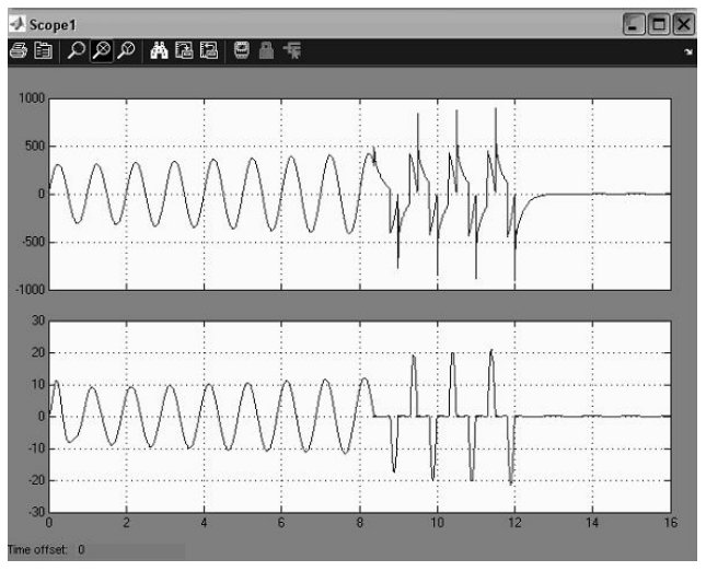
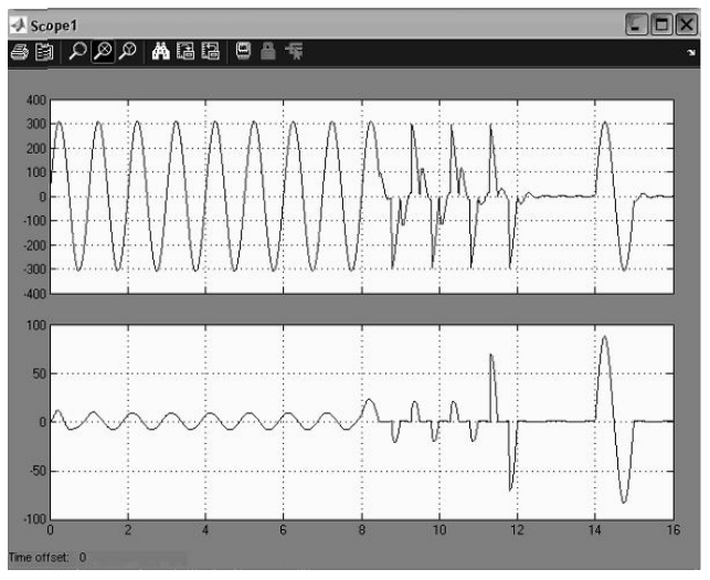
Figure 2 and Figure 3 show the results of the performed simulations. As can be seen on the presented simulations, the two-stage action assures that, in case of low over-voltages or over-currents, the average voltage value decreases and the load is not cut off from the mains supply ensuring uninterrupted operation.
Experimental results
The tests were conducted with a resistive load made of nickeline conductor, a capacitive load consisting of a capacitor bank and a movable iron core inductor. The test schematic is presented in Figure 4.
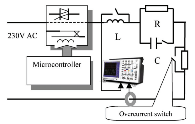
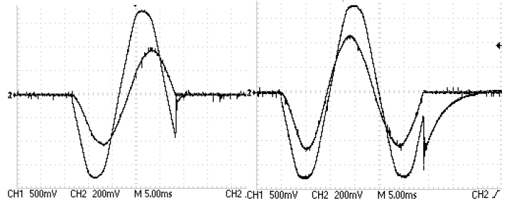
Several measurements were conducted on both constructional variants using resistive and RLC loads for different inductivities by moving the variable core. Some significant waveforms (for several load combinations with limiting values) are presented in Figures 5 and Figure 6. Each graph presents the load voltage (the sinusoid with larger amplitude) and the load current (the lower amplitude sinusoid).
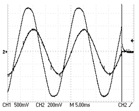
Load re-coupling and decoupling at current zero crossing can be observed, along with diminished perturbations. The relay variant generates short duration voltage surges both for load re-coupling and decoupling. For mainly inductive loads, current zero crossing produces in both variants a voltage fluctuation which is similar to those obtained by simulation.
Conclusions
The simulations show the advantages of a triac used as actuator element. This can be achieved due to the possibility of the two-stage command when detecting overcurrents or over-voltages and stepwise re-coupling of the load. However the triac command variant presents some disadvantages:
-A limiting resistor for the short-circuit current at its maximum admissible non-repetitive value of the triac is permanently connected in series with the load, for power dissipation;
-In a supply system characterized by frequent over-voltages and major load variations the lifetime of the triac decreases significantly [5];
-The behavior of loads with a variable inductive component is incompletely known.
The relay version does not allow a stepwise protection but if the consumer is decoupled at load current zero crossing, the reliability will increase. The relay should be able to operate at high switching speed and high load current (20A), which means that this version will involve higher costs. After several laboratory tests conducted with different types of loads and various power factors, the results demonstrated that the protection device operates in accordance with its design characteristics for inductive power factors (that are specific to electric transport lines) even for very low ones, as results from the presented graphs.
REFERENCES
[1] Kobes M., Groenewegen K., Duyvis M.G.: Consumer fire safety: European statistics and potential fire safety measuresReport, Netherlands Institute for Safety Nibra, 2009.
[2] Istrate M., Gusa M., Assessment Of Two Single-End Fault Location Algorithms In An ATP Approach, Revue Roumaine de Sciences Techniques – Électrotechique et Énergétique, Tome 54, 4, 2009, pp. 345 – 354.
[3] Romanca M., Ogrutan P.: Embedded Systems. Microcontroller Applications, Transilvania University, Brasov, 2011.
[4] Williams, C.: “Electronic Fuse Overcurrent Protection” in Transmission and Distribution Conference and Exhibition, 2005/2006 IEEE PES, Dallas, TX, May 2006, pp. 1226 – 1228.
[5] Chiste, A. ; Funke, J.: “Electronic systems protection via advanced surge protective devices” Proc. Telecommunications Energy Conference, Montreal, Canada,Sept. 30 – Oct. 3, 2002, pp. 22 – 26.
Authors: Prof. PhD eng. Petre Ogrutan, Transilvania University of Braşov, Eroilor Av. 29, 500036, Braşov, E-mail: petre.ogrutan@unitbv.ro; Assoc. prof. PhD eng. Elena Aciu, E-mail: lia_aciu@unitbv.ro
Source & Publisher Item Identifier: PRZEGLĄD ELEKTROTECHNICZNY (Electrical Review), ISSN 0033-2097, R. 88 NR 6/2012
