Published by CEA Technologies Inc. (CEATI), POWER QUALITY Energy Efficiency Reference Guide, Chapter 4 – Solving and Mitigating Electrical Power Problems.
4.1 Identifying the Root Cause and Assessing Symptoms
Power quality technologists employ technical instrumentation. This instrumentation can range from simple digital multi-metering through to sophisticated waveform analysis instruments. True power quality monitoring requires full-time monitoring so that steady state effects can be trended and infrequent events can be captured as they occur. A variety of electronic meters are now available for permanent monitoring that offer numerous features at moderate prices. A trained PQ specialist can also employ a portable instrument, or groups of instruments, to diagnose power quality for fixed periods of time. It should be emphasized that power quality monitoring is a highly technical and potentially dangerous skill; even many trained electricians are completely unfamiliar with the details of how power quality measurement is properly carried out.
Do not attempt to undertake a power quality measurement exercise without the help of a professional practitioner in the field.
One of the first things that should be carried out before monitoring begins is a check of the effectiveness, safety and operational characteristics of the wiring in the facility. This will ensure that problems like bad grounding, poor terminations and improperly connected loads are not masking other problems or are, in fact, not mistaken for other types of issues.
Some of the elements that might be tracked by a PQ professional are:
- RMS (Root – Mean – Square) Measurements
- Average Measurements
- Peak Measurements
- Harmonic Analysis
- Power Line Event Logging
4.2 Improving Site Conditions
Consideration of disturbance sources external to the facility should only be considered after the internal electrical environment has been thoroughly checked.
4.2.1 Mitigating Effects
The key elements to mitigate power quality problems are:
- Proper grounding and wiring
- Effective mitigating equipment (if required)
4.2.2 Mitigating Equipment
A wide variety of products are available that can help to mitigate power line disturbances. Care should be taken to properly select effective mitigating equipment. Improper application of these products may cause new power quality problems due to unforeseen incompatibilities. Before selecting a product, the customer should have a good understanding of the cause of the problem, as well as the characteristics of the available equipment. A properly functioning system may be adversely affected by change in the electrical environment, as in a change of load in the facility. Therefore, mitigating equipment that was once effective may fail to protect sensitive equipment after such a change has occurred. When selecting equipment that has an operational heat loss, as indicated by an efficiency rating, provision should be made for adequate cooling of the equipment, especially if it is to be located in a computer room.
4.2.1.1 Dedicated Circuits
A dedicated circuit is a single circuit with one load. It is a relatively inexpensive distribution technique that can reduce load interaction. The ability of a dedicated circuit to solve power quality problems depends on its location, impedance, and other factors. To achieve the lowest possible impedance, theoretically, the load of the circuit should be as close as possible to the building service entrance. However, this could aggravate the situation if transients are a problem, since they could travel more freely through the system. For improved operation of the circuit, the neutral and the ground wires should be the same size as the current-carrying conductor.
Tips and Cautions
Dedicated circuits will solve local problems only. Properly installed dedicated circuits obviate the need for isolated grounding circuits.
4.2.1.2 Surge Protective Devices (SPDs; also known as Transient Voltage Surge Suppressors, TVSS)
SPDs are energy diverters that pass the energy contained in a transient to the ground. There are a variety of designs available including gas discharge tubes, line clamps made of semiconducting material, and hybrid designs which may contain linear inductive or capacitive components. It is important to note that transient suppressors do not provide voltage regulation or isolation.
4.2.1.3 Lightning Arresters
The lightning arrester is designed to remove large overvoltages and associated high energy levels. This is accomplished during an overvoltage by short-circuiting the line to ground in what is referred to as a crowbar effect of energy diversion. The conduction of energy to ground will cease when the current drops to zero. The response time for this technology is relatively slow. These products are used as primary arresters on main power feeders.
4.2.1.4 End-User SPDs
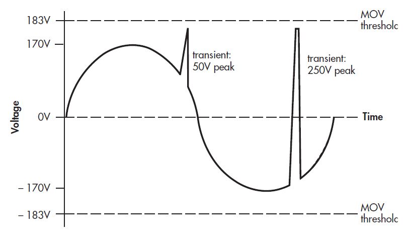
Faster-acting SPDs that use Metal Oxide Varistors (MOVs), or silicon avalanche diodes (SADs) can be used for lower-voltage transient attenuation. They act by clamping line voltage to a specific value and conducting any excess impulse energy to ground, regardless of frequency. The energy shunting capability of a line clamp is expressed by its joule rating, which determines the amount of energy the device can handle. It is important to realize that these units are only as good as the ground wiring that they are connected to; routing transient energy to ground may result in the mis-operation of some devices. In addition, they are quite susceptible to longer duration overvoltages, which can lead to catastrophic component failure. Silicon avalanche diodes operate on lower voltages, handle less power, but tend to act faster than MOVs, and are often used in communication systems for these reasons. Due to the clamping nature of a surge suppressor, it cannot remove voltage irregularities that occur within the sine wave envelope but do not exceed the limiting threshold.
4.2.1.5 Power Line Filters
Filter design is a complex topic and needs to be properly addressed by a qualified power quality practitioner.
Linear Passive Filter
Design and Operation
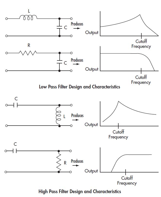
A linear filter is composed of linear components, such as inductors and capacitors. It passes the basic power frequency (60 Hz) and attenuates other frequencies which are in the form of electrical noise and harmonics. Some filters are tuned circuits, which means they address a small range of frequencies. Examples of filters that are not tuned are the simple low pass filter, and the simple high pass filter.
Uses
Simple low pass filters attenuate high frequencies, and have the general characteristics most desired in filters for improved power quality and noise attenuation. Simple high pass filters attenuate low frequencies. Tuned shunt filters are not used for general power quality applications. Special designs are used to attenuate harmonics. A shunt connected tuned filter, which consists of an inductor, a capacitor and a resistor, is tuned to eliminate a specific harmonic order by providing a low impedance to the harmonic frequency and shunting the harmonic energy to ground. A number of these filters may be arranged in stages, with each stage selectively filtering a given harmonic frequency.
Examples of Harmonic Filters
Equipment which is either sensitive to electrical noise, or which creates it, is often designed with linear filters for protection of equipment. For instance, all power supplies contain electrical filters. For harmonics, multi-staged shunt filters are most effective for mitigation of lower order harmonics.
Disadvantages
- Common mode noise is not necessarily eliminated by the use of linear filters.
- Low pass series filters are seldom used for harmonic attenuation since they must be rated for full line current making them relatively expensive.
- Shunt filters applied at individual loads can often be overloaded by harmonics produced by nearby loads or even at other customer sites.
4.2.1.6 Isolation Transformers
Design and Operation
Isolation transformers consist of two coils (primary and secondary) intentionally coupled together, on a magnetic core. They have two primary functions:
a) They provide isolation between two circuits, by converting electrical energy to magnetic energy and back to electrical energy, thus acting as a new power source.
b) They provide a level of common mode shielding between two circuits.
Since the ability of a transformer to pass high frequency noise varies directly with capacitance, isolation transformers should be designed to minimize the coupling capacitance between primary and secondary sides, while increasing the coupling to ground. Isolation transformers have no direct current path between primary and secondary windings. This feature is not characteristic of an auto-transformer, and therefore an autotransformer cannot be used as an isolation transformer. Unshielded isolation transformers can only attenuate low frequency common mode noise. High frequency normal mode noise can be attenuated by specially designed and shielded isolation transformers, although it is not frequently required (consult with your electrical system expert).
Advantages
- Isolation transformers are used to attenuate common mode noise.
- They provide a new neutral to ground reference point.
- They can be used to break ground loops.
- Isolation transformers can reduce higher order harmonics, but will not eliminate harmonic distortion or prevent notching.
- Isolation transformers may be combined with other equipment such as transient suppressors and circuit breakers to form complex circuits known as Power Distribution Units (PDUs).
- Only high quality shielded isolation transformers should be used in critical applications.
Disadvantages
- No voltage regulation or ride-through capabilities are available.
- Poorly designed isolation transformers may produce harmonics.
- The ability of an enhanced isolation transformer to attenuate normal mode noise varies, depending on the load.
4.2.1.7 Line Voltage Regulators
Design and Operation
A line voltage regulator is a device that maintains a relatively constant voltage output within a specified range, regardless of input voltage variations. Some kinds of line voltage regulators can regulate, but not “condition”, the power. They are less frequently used, and include the ferroresonant transformer, the tap switching transformer, the variable ratio transformer, the magnetically coupled voltage regulator, the induction regulator and the saturable reactor. The ferroresonant transformer and tap switcher are discussed in more detail within this section. Auto-transformers are frequently used in voltage regulation devices. If an auto-transformer is used as the variable circuit element, it develops a variable voltage which is added to the incoming AC line voltage. A sample of the input voltage is rectified, filtered and compared to a DC reference voltage. The difference is then used to off set the input voltage change. Auto-transformers are also used in Silicon Controlled Rectifier regulators. In this case, the primary voltage of the autotransformer is varied by phase control.
Uses
These products regulate voltage to protect against momentary and transient disturbances, within a certain range. Their response time is typically one cycle. Regulators are already built into some sensitive equipment. Most regulators that are built into equipment, however, are DC regulators.
Disadvantages
- Voltage regulators do not have noise suppression capabilities.
- Those with switching power supplies actually create noise in the input line.
4.2.1.8 Ferroresonant Transformers
In contrast to a typical isolation transformer, the ferroresonant transformer is designed to operate at saturation. The ferroresonant transformer provides the same functions as the shielded isolation transformer, but also provides instantaneous, continual voltage regulation, as well as ride-through capabilities. A ferroresonant transformer has a relatively simple design, and no moving parts; however this mitigation device was designed for older, linear electrical loads. A ferroresonant transformer is often incompatible with modern electronic loads and should be used with caution on high demand loads. Ferroresonant transformers usually have higher operating temperatures that can lead to very warm equipment enclosure temperatures. It is therefore recommended that these transformers be safely guarded from accidental contact by personnel.
4.2.1.9 Tap Switching Transformers
Design and Operation
An electronic tap switching transformer, or tap switcher, regulates output voltage by changing the ratio of primary windings to secondary windings in response to fluctuations in input voltage or load. This is accomplished with solid state switches (SCRs or TRIACS) which select the appropriate taps to compensate for the fluctuations. Voltage is regulated not continuously, but in steps. Switching occurs when line voltage passes through zero, so transients are not created.
- The tap switcher can react in one or two cycles.
- Either peak or RMS voltage detectors may be used.
- Taps may either be on the primary or secondary side.
Uses
Where voltage fluctuation is the primary concern.
Disadvantages
- Voltage output changes are not continuous. Better voltage continuity is achieved by using more taps.
- If auto-transformers are used, no isolation is provided.
4.2.1.10 Power Conditioners
Devices marketed as power conditioners are often combinations of the above-mentioned mitigation devices. They often contain transient voltage surge suppression, noise filters, and isolation transformers or voltage regulators. Careful consideration of product specifications and the intended use are required in order to determine if they will be effective.
4.2.1.11 UPS Systems
“UPS” means uninterruptible power supply. A UPS system contains a component that stores energy which can be used during power interruptions. UPSs are available in a wide range, from basic battery backup to units that can supply power for days. UPS systems can be on-line or off -line (standby). Typically, the on-line systems provide greater protection and cost more. These systems may be either rotary or static. Rotary systems employ rotating machines; static systems use solid state components.
A UPS does not necessarily provide protection against high energy impulses.
A properly selected UPS system is the only product, other than a generating unit, that can protect critical loads against power interruptions exceeding 0.5 seconds and which can provide active regulated power.
Some inexpensive UPS systems with low power ratings produce a square wave output, causing some loads to malfunction. This characteristic is particularly true for standby UPS systems. The problem can be avoided by selecting a UPS system with a synthesized sine wave.
Disagreement often arises as to the preferred type of system, rotary or static. Rotary systems are often criticized for the regular maintenance they require, whereas static systems are criticized for the frequency of failed components. It should be pointed out that regular maintenance and parts replacement of rotary systems helps to prevent component failures, whereas static systems can run for a significant period of time without maintenance before failure with minimal downtime. No matter what system is selected, the user should expect that some type of maintenance or replacement will eventually be required. Multiple UPS systems can be used for redundancy in critical applications. They can be arranged in parallel, in which case they normally share loads, or in isolation, so that each UPS supplies a specific load under normal operation.
Large UPS systems (>100 kVA) typically employ inverters and wet-cell batteries, which require ventilation. Care should be taken to locate these items in protected, ventilated areas. Regardless of where the system is situated, the room should be relatively free of dust, and the temperature maintained near 25°C for optimum battery life and performance. More recently designed small UPS systems (<100 kVA) employ sealed batteries, which emit no hydrogen gas, and transistorized inverters, which are very quiet. Th e batteries are mounted in a cabinet, and the whole system can be placed in a computer room. Care should be taken to ensure that adequate battery life is available for these systems.
Battery Design and Selection
A battery is an electrochemical device that converts stored chemical energy into electrical energy.
Recharge time is typically 8-10 times the discharge time. When selecting a UPS battery, the cell size, cell life, required voltage, reliability, weight/space and manufacturer’s warranty should be considered. It is also important to note that battery discharge time as a function of load is not a linear relationship. Two basic types of batteries that are used for UPS systems are lead acid and Valve Regulated Lead Acid (VRLA). Carefully consider the minimum amount of battery time that is necessary in order to reduce capital and maintenance costs in the system.
Rotary UPS
A state-of-the-art, on-line rotary UPS is one of the most effective but more costly types of UPS systems. Although a number of designs are available, they include motor-generators with battery backups and fly-wheel systems.
4.2.1.12 Isolated Grounding Outlets
An isolated ground (IG) outlet as recognized by Electrical Codes is a receptacle, orange in colour or with an orange triangle and marked “Isolated Ground”, that is wired as an individual branch circuit outlet. This outlet has a separate green or green/yellow wire along with the normal uninsulated ground wire that runs continuously from the ground conductor terminal to the first panelboard where it is connected to the ground bus. Bonding of the conduit, boxes, etc. of the circuit is accomplished by ordinary means, i.e., conduit or a separate ground wire. The two grounds are connected only at the panelboard.
Many years ago, this arrangement was implemented to reduce common-mode noise problems. Common-mode noise is better attenuated at each device in the system and is in fact effectively filtered at the input of modern electronic devices.
The IEEE Emerald Book states that:
“This type of equipment grounding configuration is only intended to be used for reducing common-mode electrical noise on the electronic load equipment circuit as described in the NEC. It has no other purpose and its effects are variable and controversial.”
Isolated grounding receptacles are no longer recommended for installation in any situation. The effects they are supposed to solve can be more easily and cheaply mitigated with robust electrical system design.
4.2.3 Preventative Measures
4.2.3.1 Distribution System Considerations for Sensitive Loads
The quality of the power supplying sensitive loads is very heavily influenced by other loads within a customer’s facility. If there are “heavy” loads such as motors or heating, ventilating and air conditioning systems being supplied, voltage drops and electrical noise can be generated causing power quality problems for sensitive loads such as computer loads. As an illustration, consider the following distribution system supplying both motor loads and sensitive electronic loads. In this case the sensitive loads are fed from phase to neutral, and motors are fed phase to phase.
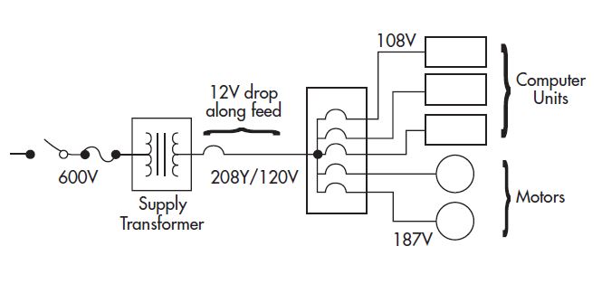
If the feeder has a resistance of 0.075 ohms, during a motor start the voltage drop along the feeder is:
V = IR = 160A x 0.075 Ω = 12V
Voltage at the sensitive loads is 120 -12 =108V
Voltage at the motors is 208 – (√ 3 x 12) =187V
If the motor is a 10 HP motor, it will draw an inrush current in the order of 160 A for a short period of time when starting.
The impedance of the feeders to the distribution panel supplying the motor and sensitive loads will cause a voltage drop of 12 volts or more while the motor is starting. Because of this voltage drop the sensitive loads will be supplied with only 108 volts for a short period of time. Unless the sensitive loads have an adequate amount of stored energy to ride through the voltage sag, they may malfunction. In addition, the current drawn for the first one or two cycles of the motor start, while the stator is magnetizing, is 2 to 3 times higher than the normal starting current. This will lead to only 84 V feeding the sensitive loads during this time.
If the motor load and the sensitive loads are supplied from separate feeders then the voltage drop does not occur in the feeder supplying the sensitive loads.

An even better approach is to effectively create a new supply system for the sensitive loads by using a transformer in addition to a separate feeder.
A transformer establishes a separately derived power source. The transformer can be of the step-down type to reduce the supply voltage to the utilization voltage of the equipment or an isolation transformer if the supply voltage is already at the appropriate voltage.
Typical voltages for computer equipment are 120 volts single phase and 120/208 volts three-phase wye. If the sensitive loads are susceptible to some form of RFI (radio frequency interference), the transformer may utilize a shield that isolates electrical and magnetic noise coupling from the primary to the secondary of the transformer. This shield is connected to ground. The neutral on the secondary of the transformer must be connected to ground per the applicable Code in your jurisdiction.
4.2.4 High Frequency Grounding Considerations
Equipment grounding and the grounding of the electrical distribution system provide a low impedance path to ground for low frequencies (mainly 60 Hz and up to the 11th harmonic). Computers and microprocessor controlled equipment operate at high frequencies (in the 100s of MHz for control devices and well into the GHz region for IT and communications equipment).
IT equipment transfers data between various pieces of equipment at very high frequencies utilizing low signal levels. In the past, where these signal levels were referenced to the local ground system, they were susceptible to electrical noise and interference. Examples of the types of interfaces that suffered from noise coupling problems were the RS-232 interface and the Centronics printer interface. Grounded interconnection standards like these have been largely superceded by isolated and higher speed connections like Ethernet, fibre optics and USB. Where older analog communications systems and digital interface standards are still used, these types of equipment need an effective means of grounding for both low and high frequencies. A more effective approach is to eliminate all ground-referenced communication interfaces in a facility with newer, higher speed and noise immune interfaces.
Effects of Frequency on Conductors
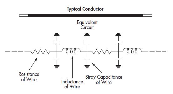
Wiring systems used within a building generally have low impedance at low frequency, but as the frequency increases the impedance increases. “Real” wiring can be modeled by a wire with resistance and inductance and stray capacitance to ground distributed along its length.
For a grounding conductor to be effective at high frequencies it must be short to minimize the effects of stray capacitance and distributed inductance along its length. A rule of thumb is that the conductor should be shorter than 1/20th of the wavelength at that frequency. This means a length shorter than 1.4 m at 10 MHz. The single point, parallel path ground, which makes for a good equipment ground, is a less reliable high frequency signal ground.
In order to satisfy both equipment grounding and signal grounding requirements, a hybrid system should be employed. This system is a combination of the parallel path ground combined with a multipoint ground for good high frequency performance.
One such method, described in IEEE 1100-1999, The Emerald Book, is a signal reference structure.
Signal Reference Structure
A ground plane is a conducting surface that has low impedance over a range of frequencies. The ideal situation would be to have all communications equipment located on a ground plane so that short connections could be made from the equipment to the plane.
While it is usually not practical to have a true ground plane, an effective alternative is a grid of conductors spaced on regular intervals, bonded at their intersections on the subfloor of a room’s raised floor, where it exists. This is called a Signal Reference Grid (SRG). In the absence of a raised floor, the bonded interconnection of equipment racks and trays at regular intervals also creates a SRG effect.
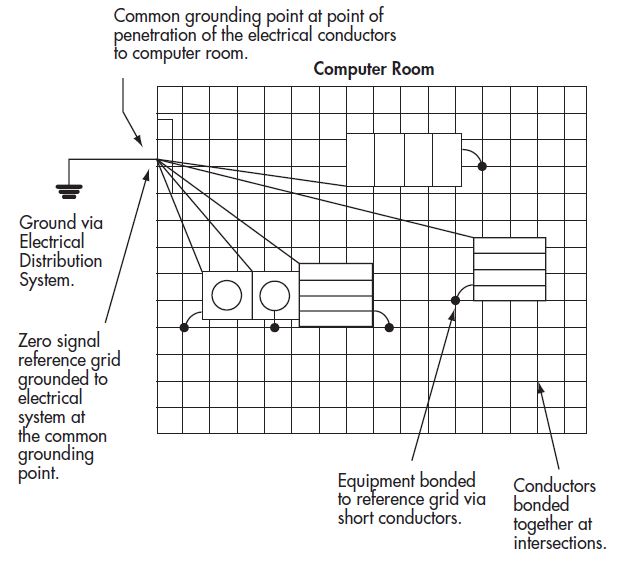
The grid is grounded to the electrical system ground at the point where the supply enters the room. All powered equipment is also grounded at this point making the equipment grounding a single point system.
Equipment is bonded to the reference grid via short conductors creating a low impedance path to ground for high frequencies. This hybrid system satisfies both equipment and high frequency grounding requirements and complies with the Electrical Safety Code. It creates a more stable and robust environment for all equipment connected to it in the event of a voltage transient or system fault impacting the electrical system.
4.3 Troubleshooting and Predictive Tips
4.3.1 Tips
Distribution Wiring and Grounding
- Check that the electrical contractor is reputable, and practices proper grounding and wiring techniques. The electrical installation should be tested with instruments to determine compliance to Codes and equipment requirements. Have all wiring inspected.
- Electrically separate highly sensitive loads from other loads. This may involve using separate buses, or separate distribution transformers. Th e Code generally does not allow separate AC services to be used in a facility.
- Ensure that all equipment is CSA certified for safety reasons. Before purchasing mitigating equipment, ensure that all distribution and grounding problems have been identified and corrected. Then identify any problems that require mitigating equipment.
- Ensure that all components of interconnected IT equipment are bonded to the same grounding system.
- For the purposes of signal grounding, never assume that two physically separated points of a ground system will be at the same potential. Use isolation techniques or current transmitters for physically separated equipment.
- If significant changes have been made in an electrical system, and a low voltage condition exists, notify the utility.
Mitigating Equipment
Ensure that overvoltage protection exists at the powerline entrance to the building and at other susceptible points
- When purchasing electrical products, ensure that they will effectively perform the functions that are required, and cause minimal degradation of the power system. It is a good idea to request a demonstration of the equipment within the plant, when possible, especially for mitigating equipment.
- Following installation of mitigating equipment, verify that the problem is solved.
- Always identify any equipment sensitivity requirements, such as sensitivity to voltage fluctuations, in specifications.
- Consider the interaction between mitigating equipment and the load. For instance, if the mitigating equipment has a high impedance, and the load has high inrush current (due, perhaps, to the starting of large motors), a voltage sag could result
- The noise suppression capabilities of some products may be specified in terms of peak attenuation, which may not be appropriate for some applications. In addition, it is important to know the conditions under which the attenuation was measured.
- Proper installation of electrical equipment is very important and yet often overlooked. For example, many ferroresonant transformers and power conditioners are improperly installed due to incorrectly sized primary conductors or breakers.
Equipment Ratings
- The purchaser should check if quoted equipment capabilities apply to units operating at no load, partial load or full load.
- All electrical equipment should be properly sized. Products may be sized by power, in volt amps (VA), or by maximum current rating in amps. To determine proper sizing, the following steps should be taken:
- Determine the load operating voltage, current, and/or VA from the nameplate rating.
- Sum all individual VA ratings of the loads. To obtain an estimate of the power consumed by the load, which is the real power in watts, calculate: Real Power = VA x Power Factor.
- Many nameplate ratings assume a power factor of unity. If this is not a good assumption, factor this in. Some units are rated in Primary Power ratings. If this is the case then the sum of all secondary loads will have to be divided by the efficiency of the unit in order to obtain the Primary Power rating. It is especially important to obtain the power requirements for sensitive loads from the manufacturer.
Best Practices
- Reduce the number of disturbance sources.
- Maintain a malfunction log.
- Customers should be aware of the level of harmonics they are producing. If a customer is exceeding the acceptable limits of the distribution system, they may be required to shut down their facility.
- To minimize problems related to voltage sags use reduced voltage starters on motors
- If installing an isolation transformer, ensure that the ground on the secondary side is properly connected.
- Above all, know and understand the technology of mitigating equipment before applying it.
4.3.2 Troubleshooting
If an electrical end-user suspects that a power quality problem exists in his facility, there are a number of steps that may be taken to troubleshoot the problem. The key is a process of elimination. Reputable consultants may be contacted by the customer to assist the process:
- Define the type of disturbance, frequency of occurrence and magnitude of the problem.
- Determine which power conductors — hot, neutral or ground — have problems; this is critical, since some mitigation techniques only address problems with a specific conductor. For grounding problems, the source of the problem must be fixed; no mitigating equipment will provide a solution.
- Check wiring for loose connections.
- Check that proposed solutions actually work and follow-up.
