Published by CEA Technologies Inc. (CEATI), POWER QUALITY Energy Efficiency Reference Guide, Chapter 2 – Understanding Power Quality Concepts.
2.1 The Electrical Distribution System
One of the keys to understanding power quality is to understand how electrical power arrives at the socket, and why distribution is such a critical issue.
Electrical power is derived from generation stations that convert another form of energy (coal, nuclear, oil, gas, water motion, wind power, etc.) to electricity. From the generator, the electricity is transmitted over long distances at high voltage through the bulk transmission system.
Power is taken from the bulk transmission system and is transmitted regionally via the regional supply system. Power is distributed locally through the distribution system and local utilities. The voltage of the distribution system is reduced to the appropriate level and supplied to the customer’s service entrance.
2.1.1 Voltage Levels and Configurations
The power supplied to the customer by the utility will be either single-phase or three phase power. Single-phase power is usually supplied to residences, farms, small office and small commercial buildings. The typical voltage level for single-phase power is 120/240 V (volts).

Three-phase power is usually supplied to large farms, as well as commercial and industrial customers.
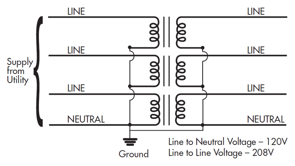
Typical voltage levels for three phase power supply are 120 V/208 V, 277 V/480 V (in the United States and Canada) or 347 V/600 V (in Canada).
Rotating equipment such as large motors and other large equipment require three-phase power to operate, but many loads require only single-phase power. Single-phase power is obtained from a three-phase system by connecting the load between two phases or from one phase to a neutral conductor.
Different connection schemes result in different voltage levels being obtained.

2.1.2 Site Distribution
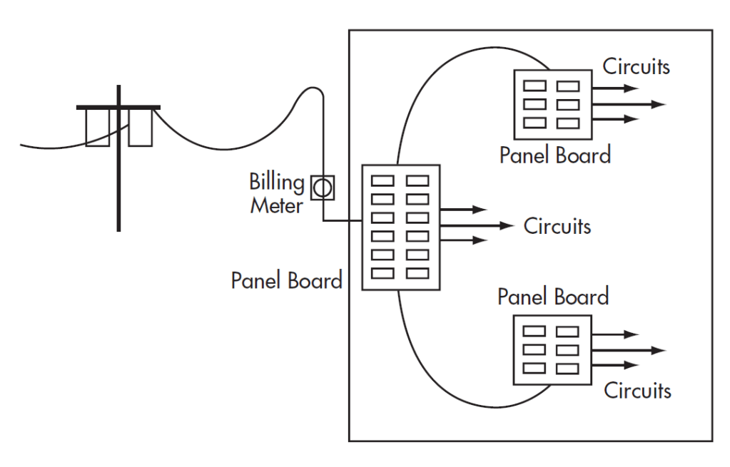
Electrical power enters the customer’s premises via the service entrance and then passes through the billing meter to the panel board (also referred to as the “fuse box”, “breaker panel”, etc.). In most residential or commercial installations electrical circuits will be run from this panel board.

In larger distribution systems this power panel board will supply other panel boards which, in turn, supply circuits.
A transformer is used if a different voltage or isolation from the rest of the distribution system is required. The transformer effectively creates a new power supply system (called a separately derived power source) and a new grounding point on the neutral.
2.2 Basic Power Quality Concepts
2.2.1 Grounding and Bonding
Grounding
Grounding is one of the most important aspects of an electrical distribution system but often the least understood. Your Electrical Code sets out the legal requirements in your jurisdiction for safety standards in electrical installations. For instance, the Code may specify requirements in the following areas:
(a) The protection of life from the danger of electric shock, and property from damage by bonding to ground non-current carrying metal systems;
(b) The limiting of voltage on a circuit when exposed to higher voltages than that for which it is designed;
(c) The limiting of ac circuit voltage-to-ground to a fixed level on interior wiring systems;
(d) Instructions for facilitating the operation of electrical apparatus
(e) Limits to the voltage on a circuit that is exposed to lightning.
In order to serve Code requirements, effective grounding that systematically connects the electrical system and its loads to earth is required.
Connecting to earth provides protection to the electrical system and equipment from superimposed voltages from lightning and contact with higher voltage systems. Limiting over voltage with respect to the earth during system faults and upsets provides for a more predictable and safer electrical system. The earth ground also helps prevent the build-up of potentially dangerous static charge in a facility.
The grounding electrode is most commonly a continuous electrically conductive underground water pipe running from the premises. Where this is not available the Electrical Codes describe other acceptable grounding electrodes.
Grounding resistances as low as reasonably achievable will reduce voltage rise during system upsets and therefore provide improved protection to personnel that may be in the vicinity.
Connection of the electrical distribution system to the grounding electrode occurs at the service entrance. The neutral of the distribution system is connected to ground at the service entrance. The neutral and ground are also connected together at the secondary of transformers in the distribution system. Connection of the neutral and ground wires at any other points in the system, either intentionally or unintentionally, is both unsafe (i.e., it is an Electrical Code violation) and a power quality problem.
Equipment Bonding
Equipment bonding effectively interconnects all non-current carrying conductive surfaces such as equipment enclosures, raceways and conduits to the system ground. The purpose of equipment bonding is:
1) To minimize voltages on electrical equipment, thus providing protection from shock and electrocution to personnel that may contact the equipment.
2) To provide a low impedance path of ample current-carrying capability to ensure the rapid operation of over-current devices under fault conditions.


If the equipment were properly bonded and grounded the equipment enclosure would present no shock hazard and the ground fault current would effectively operate the over current device.
