Published by Electrotek Concepts, Inc., PQSoft Case Study: Voltage Notching and Distribution Systems II – Large DC Drive Examples, Document ID: PQS0506, Date: June 30, 2005.
Abstract: This case study describes voltage notching associated with large DC drives. The notching is a normal characteristic of a phase-controlled rectifier but this paper illustrates problems that can occur on systems with low short circuit levels where the voltage notching can excite the natural frequency of the distribution system and cause significant distortion in the supply voltage. The notching characteristics and the interaction with the distribution system frequency response characteristics are described, along with possible solutions, An example problem and the corresponding solution associated with a large DC drive is presented.
INTRODUCTION
Adjustable speed ac and dc drives are used with very large motors (e.g. 1,000-20,000 hp) for a variety of reasons. The drives can result in significantly improved efficiency when the driven load is variable. For large motor applications on weak systems, the drives may be required for motor starting to avoid high inrush currents.
Adjustable speed ac drives (ASDs) 1000 hp and larger typically use phase-controlled rectifiers (SCRs) and a large dc link inductor to supply a relatively constant dc current to the inverter. This is known as a current source inverter (CSI) configuration. The input rectifier may be configured as a six pulse, twelve pulse, or even higher pulse number rectifier, depending on harmonic control requirements. For dc drive applications, phase-controlled rectifiers are used to supply the dc current directly to the dc motor.
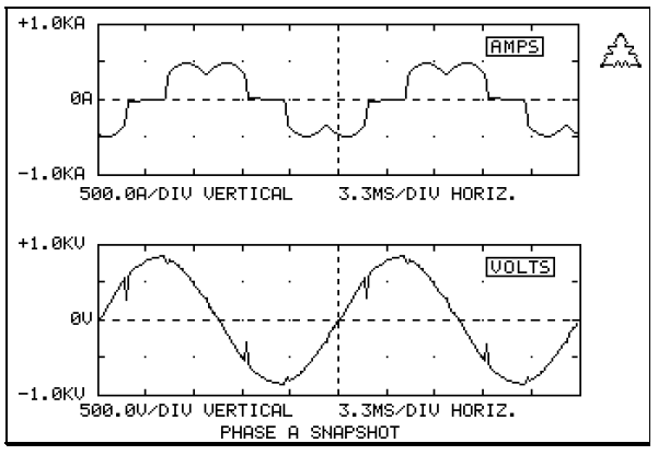
The voltage notching discussed in this paper is caused by the commutating action of the controlled rectifier. Whenever the current is commutated from one phase to another, there is a momentary phase-to-phase short circuit through the rectifier switching devices (SCRs, in this case). For a six pulse converter, this happens six times each cycle. The voltage notch is defined by its duration and its depth. The duration (commutation period) is determined by the source inductance to the drive and the current magnitude. The depth of the notch is reduced by inductance between the observation point and the drive (e.g. isolation transformer or choke inductance). An example waveform illustrating simple notches resulting from a drive operation is shown in Figure 1.
PROBLEM DESCRIPTION
On most systems, problems with voltage notching can be minimized by applying sufficient isolation reactance at the drive. This limits the notch magnitude on the source side of the isolation reactance. However, on some systems, the notches that appear at the system level can still be significant. If there is not much resistive load on a system like this, the notches can excite the natural frequency of the distribution system (determined by the capacitance of lines, cables, and capacitor banks in parallel with the system source inductance) and cause significant distortion in the voltage waveform.
Numerous papers have described the voltage notching phenomena in industrial facilities and sizing isolation reactance to limit the notching effect on other loads [1-5]. However, there has been little literature describing the potential for voltage notching to excite natural frequencies of the distribution system. The high frequency oscillations that result can cause problems with communication interference and sensitive customer loads. This paper describes the concern and possible solutions using an example where a problems was encountered. The methodology for evaluating these problems and the solutions implemented should be valuable to anyone else encountering this problem.
It is important to note that the notching problem described should only exist with large adjustable speed drives with current-source inverter configurations or with dc drives. With other types of ASDs that use voltage source inverters (e.g. pulse width modulation), the rectifier does not have a constant dc current that needs to be commutated from one switching device to another. It is this current being commutated that that essentially looks like an injection of a disturbing current into the distribution system.
LARGE DC DRIVE APPLICATION
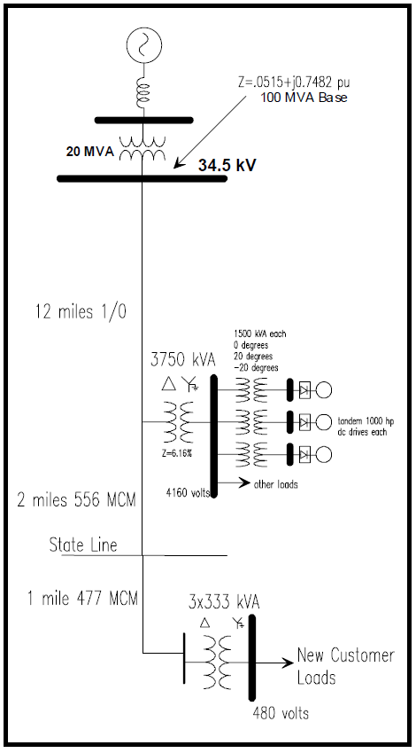
This example involves large dc drives used to pump a slurry in an industrial process. There are three sets of tandem 1000 hp dc drives used in the process. Initially, this customer was the only customer on the distribution system. Then, the distribution system was extended to supply a new customer with electronic controls for large gas turbine-driven compressors. When this new customer came on line, numerous problems were encountered, including motor heating and failures of control circuits. A one line diagram illustrating the system configuration is provided in Figure 2.
Measurements on the system indicated that harmonic distortion levels were unacceptably high on the 34.5kV system due to the operation of the dc drives. As a first step to try and solve the problem, the customer replaced the existing transformers supplying the dc drives with new transformers that had phase shifts designed to achieve 18 pulse operation for the overall facility (0 degrees, plus 20 degrees, and minus 20 degrees for the three transformers). This was effective in reducing the lower order harmonic components (when all three drives were operating) but it did not reduce the high frequency oscillation that was occurring as a result of a system resonance near the 35th harmonic. Figure 3 gives a measured waveform and spectrum from the 34.5kV system after the phase shifting transformers were put in service. Note that the distortion is spread over a range of harmonic components because the oscillation is not an exact multiple of 60 Hz. The corresponding voltage from the 480 volt service entrance at the new customer is given in Figure 4.
Effect of 34.5kV Capacitor Bank
The best solution to eliminate the high frequency oscillations that are excited by notching from the dc drives is to change the frequency response of the distribution system. This is most easily done by adding a shunt capacitor bank at the 34.5kV level. Figure 5 gives the base case frequency response characteristic showing a resonance near the 35th harmonic, along with the response for three different capacitor sizes added to the 34.5kV system near the customer with the dc drives.
At this facility, the dc drives are not always operated together. During lighter load pumping requirements, there may only be one or two of the tandem dc drives in service. During these conditions, cancellation of the lower order harmonic current components is not achieved and resonances at the 5th, 7th, 11th, or 13th harmonics could be excited. For this reason, it is important that the capacitor addition at the 34.5kV level not cause a resonance near one of these characteristic harmonics.
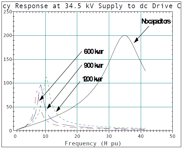

A capacitor size of 900 kVAr was selected because it results in a resonance between the 7th and 11th harmonics (see Figure 5). This capacitor is most effective when the drives are operating in the full three pump mode and there is cancellation of the lower order harmonics. When in the two pump mode, generation of lower order harmonics increases the distortion on the system but the total harmonic distortion is still less than 5%. Plots of typical profiles of the total harmonic distortion, 7th harmonic component, and 8th harmonic component over a 24 hour period are shown in Figure 6. Note that the total harmonic distortion is normally less than 4%.
With this configuration, the new customer has been able to operate without problems. However, a better long term solution would involve the addition of 5th, 7th, and 11th harmonic filters at the 4.16 kV bus supplying the dc drives. These filters would prevent resonance problems at the low order harmonics during two pump operation, even if system changes in the future (e.g. another capacitor bank added to the distribution system or at a customer location) change the 34.5kV system frequency response characteristics.
SUMMARY
The paper illustrates the characteristics of high frequency oscillations that can result from the commutation notches of large adjustable speed ac or dc drives operating on systems with relatively low short circuit levels.
The system oscillations can be magnified at customer locations where low voltage capacitors exist. Small capacitors, such as motor surge capacitors can be a particular problem. Even capacitors in the power supplies for electronic loads or smaller adjustable speed drive rectifiers can be affected by these oscillations.
The problem can be solved by careful selection of a capacitor size for the primary distribution system. The capacitor should not introduce a new resonance at one of the characteristic harmonics of the adjustable speed drive. The interaction of the proposed capacitor with other system capacitors and harmonic filters must be evaluated.
REFERENCES
- IEEE Std. 519-1992, IEEE Recommended Practices and Requirements for Harmonic Control in Electrical Power Systems, IEEE, New York, 1993.
- J.C. Read, “The Calculation of Rectifier and Converter Performance Characteristics,” Journal of the IEE, vol. 92, pt. II, 1945, pp 495-509.
- E.F. Christensen, et. al., “Analysis of Rectifier Circuits,” AIEE Transactions, vol. 63, 1944, pp. 1048-1058.
- R.A. Adams, et. al., “Power Quality Issues Within Modern Industrial Facilities, “IAS Textile Film and Fiber Meeting, Atlanta, GA., 1990.
- D.A. Jarc and R.G. Schieman, “Powerline Considerations for Variable Frequency Drives, “IEEE Transactions on IAS, vol. 1A-21, no. 5, 1985.
RELATED STANDARDS
IEEE Std. 519
GLOSSARY AND ACRONYMS
ASD: Adjustable Speed Drive
CSI: Current Source Inverter
