Published by Nahid MUFIDZADA1, Gulgaz ISMAYILOVA2, Azerbaijan State Oil and Industry University ORCID: 1. 0000-0003-4063-2128, 2. 0000-0003-0063-2020
Abstract. Overvoltage is explored on the 35, 10 and 6 kV sides of the electrical network where various characters short circuit occur on its highvoltage part. It has been revealed that the overvoltage which occurs during a short circuit has the highest values if the short circuit is single-phase, as expected. However, disconnecting of all types of short circuits results in higher, overvoltage because the network operates with an isolated neutral and a short circuit. Even when a short circuit occurs on the high voltage (HV) side of the transformer, it does not completely de-energize it. Breakdown occurs at such high currents that they cause excessive voltages. Protection against such high overvoltage can be provided by installing surge arresters at the inputs of 35 kV transformers.
Streszczenie. Przepięcia badane są po stronach sieci elektrycznej 35, 10 i 6 kV, gdzie w części wysokonapięciowej występują zwarcia o różnym charakterze. Stwierdzono, że przepięcie powstające podczas zwarcia ma największe wartości, jeśli zgodnie z oczekiwaniami zwarcie jest jednofazowe. Jednak odłączenie wszelkiego rodzaju zwarć powoduje wyższe przepięcia, ponieważ sieć działa z izolowanym punktem neutralnym i występuje zwarcie. Nawet jeśli zwarcie wystąpi po stronie wysokiego napięcia (HV) transformatora, nie powoduje to całkowitego odłączenia go od zasilania. Awaria następuje przy tak dużych prądach, że powodują one nadmierne napięcia. Ochronę przed tak dużymi przepięciami można zapewnić instalując ograniczniki przepięć na wejściach transformatorów 35 kV. (Przepięcie na stronie górnej i dolnej sieci elektrycznej Napięcie 35 kV Przy powstawaniu i rozłączaniu zwarć różnego rodzaju w części wysokiego napięcia)
Keywords: Overvoltage, short circuits, surge suppressors, switches with shunt resistance.
Słowa kluczowe: Przepięcia, zwarcia, zabezpieczenia przeciwprzepięciowe, wyłączniki z bocznikiem
Introduction
Electrical networks of 35 kV belong to distribution networks and operate with an isolated neutral. These networks are the most widespread and extensive, therefore more susceptible to abnormal and emergency conditions. The reliability of 6-35 kV networks determines the uninterrupted power supply to consumers. Emergency modes in these networks occur mainly during short circuits, which lead to an increase in either currents or voltages to high values, depending on the type of short circuit and the operating mode of their neutrals. Disabling a short circuit also leads to high overvoltage, in this case the magnetic energy of the cutting current is converted into electrical energy and increases the voltage. Consequently, the greater the breakdown current, the more overvoltage is created in the network. It is known that switches disconnect the short-circuit part of the network when the current in the switch passes through its zero value or close to this value. It should be noted here that when turning off and on, the switches of three phases operate simultaneously, while the currents of the three phases shifted relative to each other by 2π/3 degrees, do not simultaneously pass through their zero value, therefore, the switches of healthy phases operate at the moment when the currents in these phases have sufficiently large values, i.e. large currents are interrupted, and such current interruptions can cause large overvoltage as stated above [1-7].
With asymmetrical short circuits, the highest overvoltages are observed in healthy phases. On the damaged phase, overvoltage is also observed. These overvoltages that arise mainly depend on the instantaneous value and rate of change of the current in the switch at the moment of its break, on the instantaneous value of the voltages in the phases and the parameters of the circuit [3].
Problem setting
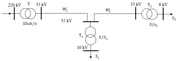
The question of what overvoltages can result from the interruption of large currents have quite great interest. This article is devoted to the consideration of this issue, as well as the transfer of such overvoltages to the secondary side of transformers, i.e. overvoltage on 10 kV and 6 kV bus systems when large currents break on the 35 kV side. The article examines a part of the electrical network in which there are three substations and two lines.
The first substation is a supply substation (SSub/S) with a voltage of 220/35 kV, the second (S/S-1) – 35/10 kV and the third (S/S -2) – 35/6 kV. To protect against overvoltages, surge arresters are installed in 35 kV bus systems. On the 10 kV and 6 kV sides there are corresponding loads S1, S2 – Fig. 1.
Solution of problems
Various forms of short circuits – one-phase, two-phase, two-phase to ground and three-phase – were performed alternately in the gap between the transformer T1 and the switches in the substation S/S-1. The results obtained are shown in Table1, as well as in Fig. 2 – 4.
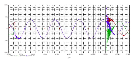
Table 1 shows the amplitude values of the currents in the first and second lines, the currents on the primary side of transformers T1 and T2.
Table 1. Currents in lines 1 and 2, on the primary side of transformer T1 and capacitive currents of lines 1 and 2
In normal operation of the network, the currents in the first and second lines are equal to 400 A and 135 A, respectively, the current in the branch of transformer T1 is 265 A, and the capacitive currents of the primary and secondary lines are 0.8 A and 0.5 A, respectively. the phase voltage values in this mode are equal – at the beginning of the first line 29.32 kV, at the beginning of the second line – 27.35 kV and the end of the second line – 26.23 kV. A, the amplitude values of the phase voltages on the 10 kV and 6 kV sides are respectively equal to 7.48 kV and 4.37 kV (see Table). All these defined values correspond to their real values during normal operation of the network in question.
In the work, it was assumed that all of the above types of short circuits occurred at the moment the voltage of phase A at the short circuit point passed through its amplitude value.
With a single-phase short circuit, there is a slight increase in the phase A current (from a value of 266 A to a value of 369 A) in the branch of transformer T1 in the S/S-1, and in phases B and C there is practically no change in currents. Changes in the current values of lines 1 and 2 are small. The current passing into the ground from the short circuit point is 164 A. This current is closed through the line capacitances, which increase to 46 A.
A single-phase short circuit leads to an increase in voltage in healthy phases. As can be seen from table. 2, at the inputs of transformer T1 in phases B and C, the voltages increase by 2.4 times. Increase in voltage at the end of line 2, i.e. on the high voltage side (HV) of transformer T2 is slightly larger – 2.7 times, due to the superposition of high-frequency voltage fluctuations created on this line. Consideration of changes in voltages and currents at the beginning of the first line and at the end of the second line (in transformer T2) is aimed at determining the influence of a fault occurring in the S/S-1 substation on these values at these specified points, which are located several kilometers from the fault point.
Of interest is the transmission of such overvoltages to the 10 kV and 6 kV sides. On these sides, there is an increase in voltage in the damaged phase by more than 1.7 times, since the current of this phase in the high-voltage part has a slightly larger change. In healthy phases there is practically no increase in voltage.
With a two-phase short circuit to ground (in phases A and B), the currents in the branch of transformer T1 increase by 7 times. The voltage in the bus systems of substation S/S-1 (at the HV inputs of transformer T1) in damaged phases drops to zero, and in the healthy phase increases from a value of 27.32 kV to a value of 42.45 kV, i.e. 1.6 times. In the bus systems of the S/S-2 substation, in phase A the voltage practically does not change, in phase B it decreases by 1.5 times, and in phase C it increases by the same amount (according to the current values of these phases at the time of the short circuit). On the low side of transformer T1 in phases A and B, the voltages are reduced by half, since the short circuit is located in these phases on the high voltage side, therefore, in the high-voltage winding there are practically no currents in these phases, therefore, in the magnetic circuit, half of the magnetic flux of the current of phase C is closed through the rod of phase A, and the other half through the rod of phase B, which leads to a halving of the secondary voltage in these phases. In phase C, the secondary voltage does not change. There is no change in voltage on the low side of transformer T2 (see Table 1).
When a two-phase fault to ground is disconnected, the capacitive currents of the damaged phases of both lines increase greatly (up to 80 A). The current passing into the ground is 245 A (see Table 1).
In the HV bus systems of the S/S-1 substation, the voltage in all phases reaches quite high values, up to 91 kV, i.e. increase by 3.5 times and this is in the presence of surge arresters at this point – fig. 3.
The voltages in the damaged phases on the high side of transformer T1 remain equal to zero, and in the healthy phase they increase excessively (as in a single-phase short circuit), since the shutdown was performed at low values of the currents of the damaged phases and at this point in time the current of the healthy phase was quite large. And, also with an isolated neutral of the network, the high-voltage winding of transformer T1 is not completely de-energized during two phase short circuits. In the case under consideration, in the high-voltage windings of transformer T1, the currents of the damaged phases are almost 140 A, and the healthy phase is 280 A.
Consequently, the disruption of such large currents leads to excessively large overvoltages. Using two contact switches in this case also does not give a positive result. A decrease in overvoltage by 2–3 times is observed, but these values remain excessively high. Installing an arrester at the HV inputs of transformer T1 overcomes this problem. Moreover, these overvoltages do not exceed 99 kV, with a duration of several microseconds, as indicated in the calculations of a single-phase short circuit. In steady state, after a short circuit, the voltages in all three phases become zero [5].
Using two contact switches in this case does not give a positive result. In this case, overvoltages are reduced by 2– 3 times, but these values also remain excessively high. And, when installing an arrester at the HV inputs of transformer T1, these overvoltages are reduced to almost 99 kV, which exceeds their nominal value by 3.7 times, remaining acceptable for a voltage class of 35 kV. These overvoltages have a pulsed form with a duration of up to approximately 10 μs – Fig. 3. In steady state after disconnecting the short circuit, the voltages in all three phases become zero.
The secondary voltages of transformer T1 also increase when the two-phase short circuit is disconnected. In phases A and B, the voltages increase from 3.88 kV (at short circuit) to 9.48 kV, and in phase C from 7.85 to 18.96 kV. The curves of these overvoltages are shown in Fig. 4. In steady state, these voltages become zero.
Both in transformer T1 and in transformer T2, on the HV and LV sides, the voltages of phase A differ little from their nominal values, and the voltages of phases B and C exceed their nominal values by more than 3 times [6].
With a two-phase short circuit (also in phases A and B), the currents of the damaged phases in the branch of transformer T1 increase greatly (almost 11 times), and the change in the current of phase C is small (100 A). The short-circuit current is 2940 A. The voltage in the HV bus systems of the S/S-1 substation in the damaged phases drops from a value of 27.32 kV to a value of 15 kV and does not change in the healthy phase. The voltage changes in the HV bus systems of substation S/S-2 are the same. The voltage on the secondary side of transformers T1 and T2, in phases A and B, is reduced by half, and in phase C remains unchanged (as with a two-phase ground fault). But disconnecting such a short circuit greatly changes all the voltages in the circuit under consideration. Voltages in all phases of the 35 kV bus system of substation S/S-1 increase three times, and in the high voltage bus systems of substation S/S-2 such an increase in voltage occurs only in phases B and C. In phase A the voltage increase is small. Disabling a two-phase fault, as well as disconnecting a single-phase fault and a two-phase fault to ground, leads to excessively large overvoltage values on the primary and secondary sides of transformer T1. In the presence of surge arresters on the HV waters of transformer T1, these overvoltages are reduced on this side to 99 kV and on the LV side to 19 kV in phases A and B, and 38 kV in phase C. As can be seen, 38 kV is 5 times the nominal value of this voltage, which is quite high. On the secondary side of transformer T2, the voltages in phases B and C increase by approximately 3.5 times, and the voltage in phase A changes little. In steady state after a short circuit, the secondary voltages T1 are equal to zero, and T2 are equal to their nominal values.
Of course, a three-phase fault (and a three-phase fault to ground) does not create overvoltages, but disconnecting this type of fault leads to fairly high values of overvoltages, since the currents of a three-phase fault have the highest values compared to currents in other types of faults. In the case under consideration, the three-phase short circuit currents reach 3450 A, exceeding the rated currents by 13 times.
As can be seen from table 1, with a three-phase short circuit, in the HV bus systems of the S/S-1 substation, the voltages in all three phases drop to zero. In the HV bus systems of the S/S-2 substation, the voltage of phase A differs little from its nominal value, and the voltages of phases B and C are reduced by more than half their nominal values. This form of voltage change also occurs in the secondary winding of transformer T2. As for the secondary voltages of transformer T1, these voltages are zero, since on the high side of this transformer the voltages of all three phases are zero.
When a three-phase short circuit is disconnected, almost four times the rated voltage is set in the HV bus systems of substation S/S-1, and three times in the bus systems of substation S/S-2. The voltage at the short-circuited inputs of transformer T1 after disconnecting the short circuit increases from zero to 31.84 kV with a duration of approximately 0.1 s – Fig.4. The secondary voltages of transformer T1 are equal to zero, since the primary voltages of this transformer are equal to zero. And, the secondary voltages of transformer T2 increase significantly. The increase in phase A is approximately 2 times, in phase B – 4.3 times and in phase C 5 times. Note that with a three-phase fault to ground, due to the direct connection of the transformer T1 inputs to the ground, the voltage in them remains equal to zero when the fault is turned off [7].
Conclusions
1. Overvoltages occurring during a single-phase short circuit have higher values than overvoltages occurring during other types of short circuit. In the considered 35 kV network diagram, with a single-phase short circuit, the overvoltage factor reaches 2.4.
2. Disabling all types of asymmetrical short circuits leads to excessively high overvoltages, which have pulse forms with a very short duration.
3. When performing surge protection for 35 kV networks, one should also take into account the overvoltages that occur when disconnecting a short circuit, at which these overvoltages reach excessively high values. The use of two contact switches to interrupt faults reduces these overvoltages, but the reduced values also remain unacceptably high. Protection against such overvoltages can be achieved by installing surge arresters at the transformer inputs.
REFERENCES
[1] Florkowska B., Florkowski M., Zydroń P., Pomiary i analiza wyładowań niezupełnych w układach izolacyjnych wysokiego napięcia przy narażeniach eksploatacyjnych, Przegląd Elektrotechniczny, 2010, 4, 241-244.
[2] Florkowski M., Forkowska B., Rybak A., Zydron P., Migration effects at conductor / XLPE interface subjected to partial discharges at different electrical stresses, IEEE Trans. on Diel. and Electr. Insul., 2015, 22, 456 – 462.
[3] N.Mufidzade, G.Ismayilova, E.Huseynov. “Effect of line carnation on overvoltage in transformers of rated voltage 330 kV”. International Journal on “Technical and Physical Problems of Engineering” (IJTPE), Iss. 51, Vol. 14, № 2, Jun. 2022.
[4] A. Shimada, M. Sugimoto, H. Kudoh, K. Tamura, and T. Seguchi, “Degradation distribution in insulation materials of cables by accelerated thermal and radiation ageing,” IEEE Transactions on Dielectrics and Electrical Insulation 20, pp. 2107, 2013.
[5] A. Shimada, M. Sugimoto, H. Kudoh, K. Tamura, and T. Seguchi, “Degradation mechanisms of silicone rubber (SiR) by accelerated ageing for cables of nuclear power plant,” IEEE Transactions on Dielectrics and Electrical Insulation 21, pp.16, 2014..
[6] Kadomskaya K. P., Lavrov Yu. A., Reichertt A. Overvoltage in electrical networks for various purposes and protection against them. Novosibirsk, Publishing house of NSTU, 2004.
[7] F.Kh. Khalilov. Overvoltage classification. Internal overvoltage. Edition, Energy Training Center, St. Petersburg, 2013. 2. AC switches for voltages above 1000 V. General technical conditions. Instead of GOST-687-70 and GOST 687-67. Gos.com. USSR by standards. – M., 1979, 98 p
Source & Publisher Item Identifier: PRZEGLĄD ELEKTROTECHNICZNY, ISSN 0033-2097, R. 100 NR 9/2024. doi:10.15199/48.2024.09.41
