Published by Marta BĄTKIEWICZ-PANTUŁA, Wrocław University of Science and Technology
ORCID: 0000-0002-1628-1818;
Abstract. The article presents the issues of designing electric vehicle charging stations. The general requirements that a vehicle charging station should meet are presented. The article focuses on the electric part of the vehicle charging station. Attention was also focused on the safety rules for installing vehicle charging stations.
Streszczenie. W artykule zaprezentowano problematykę projektowania stacji ładowania pojazdów elektrycznych. Zaprezentowano ogólne wymagania jakie powinna spełniać stacja ładowania pojazdów. W artykule szczególną uwagę poświęcono części elektrycznej stacji ładownia pojazdów. Zwrócono uwagę na zasady bezpieczeństwa instalowania stacji ładowania pojazdów. (Problemy projektowania stacji ładowania pojazdów elektrycznych)
Keywords: electrical installations, electric vehicle charging stations, installation safety
Słowa kluczowe: instalacje elektryczne, stacje ładowania pojazdów elektrycznych, bezpieczeństwo instalacji
Introduction
The dynamic development of electromobility in the world and its dynamic development as transport based on electric vehicles is caused by the world’s climate policy and the EU’s low-emission policy. At the end of 2022, Poland recorded a total of 62,135 passenger and commercial cars with electric drive [11]. There were 59.187 electric passenger cars on Polish roads. Fully electric cars accounted for 29.780 units of this part of the vehicle fleet, and the remaining part were plug-in hybrids – 29.407 units. The smallest group are electric delivery vans and trucks with 2.948 units and electric mopeds and motorcycles – 16.160 units. Low sales electric cars in Poland may be caused not only by the high price but also by the small number of public charging points for electric vehicles. Most customers are afraid that they may have problems if the car is unloaded during a long route, long charging times and frequent stops. There were 2.527 publicly available electric vehicle charging stations in Poland, which translates into 4.913 points. 29% of them were fast charging stations with direct current (DC), and 71% – slow chargers with alternating current (AC) with a power of less than or equal to 22 kW [11]. Polish drivers, despite many incentives, are afraid of the low range of electric cars. Approximately 76% of Poles believe that electric cars will not provide them with an adequate range, even though the average number of kilometers traveled by an average driver is approximately 51 km per day [12]. The study also shows low awareness of respondents about the possibility of charging an electric car at home. 83% of respondents do not know what needs to be done to install a home charging station. Appropriate development of electromobility is only possible with the creation of a large number of charging stations and continuous education of society.
The development of electromobility has many advantages. Apart from being low or zero-emission, electric cars can also be a source of power that can release energy in the event of peak demand. Cars can be charged in “night valleys” where energy demand is low. Flattening the daily energy consumption curve may result in savings due to fewer generating units to maintain. The use of electric cars for transport is a way to achieve greater energy security.
The growing number of electric cars increases innovation and creates new structures and modes of charging stations. Technologies are developed not only by car manufacturers, but also by producers of electrical equipment. Converter systems can be installed inside the vehicle, which allows you to charge the car from a regular home socket. However, this does not provide sufficient power and fast charging time. A better solution are higher-power charging stations with an appropriately adapted transformer and protection system. The most dynamically developing technology are charging stations with a built-in converter system of sufficiently high power.
Currently, charging systems available on the market can reduce charging time to 30 minutes, using power up to 350 kW and charging with a DC voltage of 400 or 800 V. Many institutions are conducting development work to safely reduce charging times.
A typical charging station is powered by a 50 Hz mains transformer and has appropriate higher harmonic filters and reactive power compensators. The diagram of the charging station is shown in Figure 1.
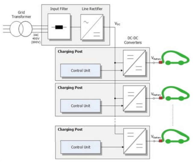
The central system also consists of a main rectifier that converts alternating voltage into direct voltage and supplies individual charging points. Individual charging points consist of a control system and a DC/DC converter. The control system is responsible for controlling the charging current and ensuring an appropriate level of safety. There are also single systems that have their own system of transformer, filters, rectifiers and DC/DC converters. Systems using direct voltage have an additional advantage because they allow photovoltaic panels to be connected to the direct current line. The station itself should also have a counter system that counts the amount of energy used during charging and appropriate overload and residual current systems.
Electrical installation at a vehicle charging station
Charging stations are used to transmit electricity to the batteries of electric cars without an internal combustion engine (EV) and cars with an internal combustion engine and an electric engine enabling battery charging (PHEV). EVs and PHEVs have an electric motor and electrical energy storage devices that can be charged from a source outside the vehicle and can be driven on public roads and highways. Charging is done by adjusting the appropriate level of voltages and currents. Chargers can be divided into external and built-in to the vehicle. External chargers are connected to the AC mains and have a built-in AC/DC converter. DC energy is supplied to the vehicle. There are also dedicated charging stations intended for specific vehicles, which have a specific communication standard and have control charging functions. Vehicle-mounted chargers have a built-in converter system inside the vehicle. The PN-EN 61851 standard “Wired charging system for electric vehicles” [1] divides chargers into 4 modes. The first three modes are AC chargers. In this case, the device that converts alternating current into direct current is located in the vehicle. The fourth mode are chargers with a built-in AC/DC converter that transmit energy to the vehicle in the form of direct current. Charging mode 1 is the slowest system. It does not have a dedicated anti-shock protection system or a communication system between the charger and the car. Mode 2 systems are systems that achieve a charging power of up to 22 kW. The plug-in has 2 additional connectors: Control Pilot and Proximity Plug. They are responsible for communication between the vehicle and the charging station, preventing the flow of current when the plug socket is not properly attached. Additionally, stations of this mode have built-in residual current devices. Mode 3 chargers are permanently connected to the network. As in the case of mode 2 chargers, they have communication and protective cables. Chargers of this mode achieve power above 22 kW. The fourth mode of chargers has a built-in AC/DC converter. The plug is equipped with “+” and “-” DC contacts. These chargers achieve the shortest charging times and the highest powers. For safety reasons, only the plugs on the car side have such a station [9].
Mode 2, 3 and 4 chargers must be equipped with the function of checking whether the vehicle is properly connected, checking the continuity of the protective conductor connection, and switching the power source on and off. For these modes of chargers, it is mandatory to include a control cable whose pin in the plug is marked “Control pilot”. Class 2, 3 and 4 loaders can be optionally equipped with:
• control of power flow to and from the car,
• regulation and detection of the load current of power supply devices, which cannot exceed the permissible load values,
• regulation of the charging rate to ensure appropriate conditions and speed of battery charging,
• regulation of ventilation of power supply devices.
Additionally, the vehicle should have built-in protection against starting and unintentional driving while the battery is charging.
Several methods of protection against electric shock are used in charging stations:
• additional or reinforced insulation,
• equalization of potentials of all metal elements,
• automatic power disconnection,
• shielding,
• separation of hazardous elements.
The charging station is exposed to various weather conditions and should undergo appropriate tests to ensure safe operation and protection against electric shock. Tests should be performed at nominal voltage and maximum current. The charging station must be resistant to temperatures ranging from -25 ˚C to 40 ˚C and relative humidity ranging from 5 to 95%. It should be adapted to work at atmospheric pressure from 860 to 1060 hPa. At the maximum ambient temperature, the gripped elements cannot exceed the temperature of 60 ˚C for non-metallic elements and 50 ˚C for metal elements. For components that may be affected, these temperatures are 85 ˚C and 60 ˚C, respectively.
There should be appropriate marking on the charging station housing containing information about the basic parameters, i.e. [2]:
• nominal voltage Un [V],
• nominal current In [A],
• nominal frequency fn [Hz],
• The manufacturer’s name,
• serial number of the device,
• date of production,
• number of phases,
• IP degree,
• if the station is intended for internal use, it should have such information
A PWM signal is used to communicate between the charging station and the vehicle. Pulse width modulation control is used to control the operation of the charger and to ensure safe operation of the device and its operation. By using this operating mode, there is no need to manually adjust the battery charging current, which provides protection against exceeding the maximum rating of the cable, which could result in a breakdown. This function is used in mode 2 and 3 chargers. The PWM signal is also used to protect the seat and the user when the plug is not connected or is not properly seated in the socket.
In addition to the power and grounding contacts, the vehicle plug must be equipped with two additional contacts [2]:
• control contact,
• testing contact.
The control contact is used to communicate the charger with the car via a PWM signal. Through this signal, the charger receives information about whether the plug has been correctly installed in the socket and whether the protective wire has been properly connected and, consequently, whether the vehicle body has been grounded.
The testing contact is responsible for detecting the connection of the plug and socket and determining the maximum current that can flow through the cable without damaging the insulation. Damage to the insulation could pose a risk of electric shock. This system therefore provides protection against electric shock.
The battery is charged using appropriate converter systems. The charging station system is connected to an alternating current network with a voltage of 230 V and a frequency of 50 Hz. Typical charging systems consist of an AC/DC/AC/DC sequence. The first system is a diode rectifier system whose task is to rectify the voltage. The next device installed is a power converter that converts direct voltage into high-frequency alternating voltage. A high-frequency isolation transformer is connected to the system, ensuring isolation of the inverter system from the rectifier.
The last element is the rectifier system, which provides the appropriate battery charging voltage. There are three rectifier systems for powering charging stations:
• single-phase 2-pulse,
• three-phase 6-pulse,
• three-phase 12-pulse powered by transformers connected in star-delta Yd and star-star Yy.
In low-power systems, single-phase 2-pulse and three-phase 6-pulse rectifiers are used. In high-power systems, 12-pulse systems with a double secondary winding or two transformers are used. The use of a 12-pulse system instead of a 6-pulse system reduces the number of harmonics of the current drawn from the network. The voltage rectified by such a converter also has smaller ripples. There are two types of DC/DC converters:
• non-insulated system,
• system with an isolation transformer.
These systems are used to lower or increase the output voltage of battery charging. The output current of the system can be smoothly adjusted, ensuring the optimal level of battery charging. Non-isolated systems consist of a controlled transistor and a filter choke. They have the ability to regulate voltage without the need to use a transformer. The disadvantage of such a system is the lack of isolation of the power supply side from the load. Isolated systems additionally have a high-frequency transformer that provides galvanic isolation of the primary and secondary sides. This insulation is an additional form of protection against electric shock.
The use of a rectifier system based on semiconductor non-linear diode elements is a source of higher harmonics of the current drawn from the network. The current consumed by such a system is strongly distorted, which causes additional active power losses in the network lines supplying the stations and in the power supply transformers. A modern approach to the construction of converter systems is the use of a bidirectional system with the possibility of feeding energy into the grid. This arrangement has many advantages because it can improve the stability of the distribution network. Vehicles connected in this way can transmit energy to the grid in the event of peak energy demand and consume it when the demand is lowest, e.g. at night between 9 p.m. and 7 a.m. The name of such a technology is called V2G. In this case, the system operator can control the power flow as in SmartGrids systems. Such systems can constitute a source of reserve power and stabilize the voltage level in the low-voltage network. In such a system, instead of diode bridges, converter systems based on transistors with an insulated gate IGBT or power MOSFET transistors made of gallium nitride GaN or silicon carbide SiC are used. This system includes a bidirectional AC/DC converter and a DC/DC converter. The AC/DC converter acts as an active rectifier or inverter in the mode of feeding energy into the grid. The use of a controlled rectifier reduces the harmonic amplitude of the current drawn from the network, which results in the consumption of undistorted sinusoidal current. The harmonic THD value is below 5%. Such a system can additionally act as a reactive power compensator in the network.
Modern systems can be additionally equipped with active decoupling systems, the purpose of which is to increase the voltage. The use of such a system allows for the replacement of electrolytic capacitors, which occupy a very large part of the volume and mass of the charger, with polypropylene foil capacitors.
Safety of installing electric car charging stations
Charging stations are powered by alternating voltage up to 1000 V. The value of such voltage may vary up to approximately ±10% Un, and the frequency of such a power source should be 50 Hz ±1%. Charging stations should have additional battery power that will release the plug lock and allow you to disconnect the cable.
The loaded vehicle is connected to the charging station via a cable assembly consisting of a flexible cable and a connector or plug. The cable includes:
• power and control cables responsible for communication and control
• ground wire
The continuity of the cable between the vehicle and the charging station should be constantly checked throughout the charging process.
The plug must be equipped with a mechanical device to prevent disconnection during charging. When connecting the plug to the socket, the ground connection must be made first, followed by the control connections. When disconnecting, the last conductor to be disconnected must be the protective conductor.
The standard [2] prohibits the use of adapters for various types of sockets and plugs. The use of such adapters may only occur in special cases indicated by the vehicle manufacturer. Such adapters must be specifically marked.
There are three types of wire connection systems:
• the cable is permanently connected to the vehicle and with a detachable plug on the AC side of the mains using a domestic or industrial socket
• connecting the charging station to the car using a cable detachable on both sides,
• the cable is permanently connected to the charging station, i.e. an alternating current source, and is plugged into the car using an appropriate plug.
The rated voltages and currents of the cable must correspond to the rated values of the rectifier. The rated voltage of the cable cores must be selected to correspond to the charging voltage of the station. The rated current of the cable should be selected according to the rated current of the circuit breaker. The cable should also have adequate mechanical strength, fire resistance, UV radiation resistance and resistance to chemical agents. The total length of the cable connected to the car cannot exceed 5-10 m (maximum cable lengths vary by region of the world).
Sockets and plugs for charging electric cars are selected according to the power and type of current and should have an appropriate IP rating. The IP rating for individual elements varies depending on the location of the charger installation: internal and external.
When constructing a charging station, the most important aspect is the isolation of hazardous parts, i.e. ensuring basic protection. Car charging stations are divided into class I and II. Class I chargers have basic insulation and a protective connection to protect against damage. In this type of chargers, all exposed parts are connected to a protective terminal. Class II chargers have basic insulation and additional insulation that protects the cable against damage. These chargers do not have a protective clamp [5].
After disconnecting the charger, the maximum voltage that may occur between active parts or active parts and ground is 42.4 V peak voltage or 60 V DC voltage. The energy stored between such parts cannot exceed 20 J. The cables and housing of the charging station must be puncture-resistant. Testing for breakdown conditions involves applying a much higher voltage. In the case of class I insulation, it involves applying a voltage equal to Un + 1200 V effective voltage, where Un is the charging voltage between the conductive phase and the neutral wire of the grounded system. The test should be performed for 1 minute. For class II insulation, the specified voltage should be 2*(Un+1200) V. The test can be performed for alternating voltage with a frequency of 50 or 60 Hz or direct voltage – in this case, the direct voltage value must equal the peak alternating voltage value. The resistance value for class I insulation must be greater than 1 MΩ, and for class II insulation – 7 MΩ.
Charging stations should be equipped with a residual current device, RCD. This device is responsible for passing current under normal operating conditions and interrupting the charging circuit when the differential current reaches the threshold value. The residual current device must have the A characteristic specified in the standard PN-EN 61008-1 – Residual current circuit breakers without built-in overcurrent protection for household and similar use (RCCB) – Part 1: General provisions [3]. This device protects against indirect contact in the event of a failure or incorrect connection. The residual current device must ensure correct operation for a residual current threshold value not greater than IΔn< 30 mA and DC current leakage above 6 mA. The charging system must operate in such a way that it does not introduce additional direct, non-sinusoidal currents and harmonics that could disturb the operation of the residual current device. The choice of the appropriate switch depends on the specifications of the charging station and safety standards.
Summary
Recently, alternating current charging has been a very common and most frequently used method of charging car batteries. There are charging station designs available on the market with high-power electronic converters, which, due to their parameters, can charge the battery in less than half an hour, which is why they are gaining popularity. The development of the electric car market has resulted in the creation of many designs and standards of charging systems. The selection of a specific solution depends on the type of access to the electrical network, the type of charging current and the standard used by car manufacturers. Each vehicle charging station should meet all safety requirements. Such electrical devices must have appropriate insulation, protective devices, including residual current devices, and communication standards that enable charging only after connecting to a car. Power electronic systems are a very important element of a DC charging station. Such an installation must have protection against electric shock and overvoltage to be safe for the user and for the electrical installation.
Improper installation usually results in network overload and direct current leakage. In the first case, the overcurrent fuse will be turned off because the current consumed by the charging station will be too high. However, in the second case, the RCD will be activated, which will disconnect the voltage when direct current appears as a result of, for example, damage to the insulation of the DC installation wires or damage to the built-in power electronics.
According to the information contained in the PN-HD 60364-7-722:2019-01 [4] and PN-IEC 60364-4-41:2000 [5] standards, for the proper use of electric car charging stations, the station should be equipped with the following functionalities:
• verification of correct connection of the vehicle to the charging station,
• possibility of applying voltage to the station output only after the vehicle is properly connected,
• real-time continuity test of the protective conductor,
• turning off the voltage at the station output after a control circuit failure or providing information about the maximum allowable charging current to the vehicle being charged.
• ensuring automatic power off,
• double or reinforced insulation,
• galvanic separation,
• SELV/PELV power supply.
A properly designed electric car charging station must be equipped with a switch that disconnects the power supply when a DC leakage is detected. You should consider where to mount the switch. The normative documents do not specify on which side of the charging station or electrical installation it is to be installed.
REFERENCES
[1] PN-EN 61851-1:2019-10 Wired charging system for electric vehicles – Part 1: General requirements.
[2] PN-EN 62196-1 Plugs, plug sockets, vehicle connectors and vehicle plugs – Wired charging of electric vehicles – Part 1: General requirements.
[3]PN-EN 61008-1:2013-05 – Residual current circuit breakers without built-in overcurrent protection for household and similar purposes (RCCB) – Part 1: General.
[4]PN-HD 60364-7-722:2019-01 Low voltage electrical installations. Requirements for special installations or locations – Power supply for electric vehicles
[5]PN-IEC 60364-4-41:2000 Electrical installations in buildings – Protection for safety – Protection against electric shock.
[6] Chudy, A.; Stryczewska, H. D. Electric vehicle charging – aspects of power quality and electromagnetic compatibility. Journal of Automation, Electronics and Electrical Engineering,1 (2019), 17-22
[7]Islam M., Shareef H., Mohamed A., A Review of Techniques for Optimal Placement and Sizing of Electric Vehicle Charging Stations, Przegląd Elektrotechniczny, R. 91, nr 8 (2015)
[8] Yong, J. Y.; Ramachandaramurthy, V. K.; Tan, K. M.; Mithulananthan, N. Bi-directional electric vehicle fast charging station with novel reactive power compensation for voltage regulation, International Journal of Electrical Power & Energy Systems, 64 (2015), 300-310
[9]Chudy, A.; Mazurek, P. Electromobility – the Importance of Power Quality and Environmental Sustainability., J. Ecol. Eng., 20 (2019), No. 10, 15-23
[10] Pilimon Ł , Jarnut M. , Szott M. Regenerative testing system for electric vehicles charging station, Przegląd Elektrotechniczny, R. 98, nr 3 (2022)
[11]https://napradzie.pl/2022/12/17/licznik-elektromobilnosci-popolskich-drogach-jezdzi-wiecej-osobowych-bev-niz-phev/
[12] https://www.wyborkierowcow.pl/polacy-chca-autelektrycznych-ale-ich-nie-kupuja-dlaczego/
[13]https://www.semikron-danfoss.com/industrial-applications/carcharger-stations/application-examples.html
[14] https://deltrixchargers.com/about-emobility/charging-modes
Author: dr inż. Marta Bątkiewicz-Pantuła, Wrocław University of Science and Technology, Faculty of Electrical Engineering, Power Electrical Department, ul. Wybrzeże Wyspiańskiego 27, 50-370 Wrocław, e-mail: marta.batkiewicz-pantula@pwr.edu.pl
Source & Publisher Item Identifier: PRZEGLĄD ELEKTROTECHNICZNY, ISSN 0033-2097, R. 100 NR 6/2024. doi:10.15199/48.2024.06.58
