Published by 1. Piotr GRYGIEL1,2, 2. Jan TARŁOWSKI2, 3. Krzysztof MIK3, Gdańsk University of Technology (1), Xdisc S.A.,Warsaw, Poland (2), Energy Conversion and Renewable Resources Research Centre, Polish Academy of Sciences, (3) ORCID: 1. 0000-0003-2769-9088; 3. 0000-0002-9510-3066
Abstract. Two types of full-size photovoltaic modules for on-grid systems with maximum DC voltage of 600 V have been developed and prepared for production. With carefully selected materials and dedicated manufacturing processes the weight of 3.5 and 3.2 kg, the power as high as 220 and 200 Wp and efficiencies of 20.1 and 21.3% were obtained. Together with standard mounting systems the devices make it possible to build nonintrusive installations on low-load capacity roofs with various types of covering, particularly in large-scale lightweight buildings.
Streszczenie. Zaprojektowano, opracowano i przygotowano do produkcji dwa rodzaje pełnowymiarowych modułów fotowoltaicznych do pracy w systemach on-grid o napięciu stałym do 600 V. Dzięki starannie dobranym materiałom i dedykowanym procesom wytwarzania uzyskano wyroby o masie 3,5 i 3,2 kg, mocy 220 i 200 Wp oraz sprawności 20,1 i 21,3%. Urządzenia, przy standardowych sposobach montażu, umożliwiają budowę nieinwazyjnych instalacji na dachach o małej nośności z różnymi rodzajami pokryć, także budynków wielkogabarytowych o konstrukcji lekkiej. (Komercyjne lekkie moduły fotowoltaiczne do zastosowań w systemach on-grid)
Keywords: lightweight photovoltaic modules, on-grid systems, low-load capacity roofs, large-scale lightweight buildings.
Słowa kluczowe: lekkie moduły fotowoltaiczne, systemy on-grid, dachy o niskiej nośności, wielkogabarytowe budynki o lekkiej konstrukcji
Introduction
The vital importance of photovoltaic (PV) systems in generation of renewable energy is nowadays beyond doubt. Indeed, the assumed global electricity demand by 2030 will increase from the current 23,000 TWh to more than 30,000 TWh. Considered in most markets as the cheapest source of electricity, the PV (and wind) facilities are expected to cover this growth almost completely with the generation share rising from less than 10% in 2020 to about 30% [1]. Regarding the PV power capacity in European Union, the value of ca. 0.16 TW was recorded at the end of 2021 which is a 15% increase compared to 2020 [2]. Note that the levels as high as 0.63 TW by 2025 and 1.94 TW by 2050 are required to achieve the carbon-free energetics [3].
In Poland, the PV capacity amounted to 7.67 GW at the end of 2021, while in the first quarter of 2022 it reached 9.4 GW, exceeding the power of wind systems for the first time. For 2022-2025, an increase of 14 GW is forecasted to reach a capacity of 21.6 GW. Importantly, although micro installations accounted for the largest share of the Polish PV market in 2021, growth in business systems and PV farms is expected in the following years [2].
Accordingly, in recent years, in-field application of various PV systems in Poland has been the subject of multifaceted research. Particularly, the influence of operation conditions on the systems’ electrical parameters was investigated ([4,5]). In [6] the reduction of PV module efficiency due to formation of dust-layer was examined. Next, the impact of shading on the performance of a distributed panels’ system was reported in [7].
An obstacle to the extensive application of PV technology is the issue of the large weight of conventional modules. Indeed, the values between 12 and 20 kg/m2 are quoted (see e.g. [8,9]). This, together with additional mass of fixing systems, makes the use of such devices on roofs with low-load capacity problematic or even impossible. Certainly, in the case of production halls, supermarkets, farms, etc expensive structural reinforcement is usually required prior to applying conventional heavy PV modules. Importantly, the structural design of existing buildings is usually on the brink of standard requirements. The issue can be solved by utilizing the lightweight PV (LPV) devices which in turn creates a market niche for LPVs, attractive due to the huge area of low-load roofs. Note that in the absence of a strict definition, units below 7 kg/m2 are considered as LPVs [10]. The LPVs can be installed using fixings as for conventional PV modules or bonded directly by adhesives. This is known as the building attached photovoltaics (BAPV). A distinction, however, should be made between BAPV and building integrated photovoltaics (BIPV) which are PV devices that replace conventional elements of building envelope [11], e.g. roof tiles (see e.g. [12]).
Following expectations for LPVs, a concept in which PV cells are sandwiched between polymeric front- and back-sheets has been developed. Therefore, glass plates and aluminium frames have been eliminated with their contributions to the weight of conventional structures of, respectively, ca. 69 and 11% [13]. Such structures were the subject of extended investigations (see e.g. [9,14,15,16]). Note that small (single- and double-cell) and medium-area (12- and 16-cell) modules were studied, with obtained structure mass of about 6.5 kg/m2 [9] and 5 kg/m2 [15]. The devices were successfully subjected to selected (thermal cycling, damp-heat and hail resistance) tests imposed by IEC 61215–2:2016 industrial procedures.
Modules design
As a response to market conditions, four full-sized prototypes of LPVs have been designed, developed and manufactured by Xdisc S.A. The following parameters were assumed to be achieved in the designing process: (i) the 19% minimum efficiency, (ii) maximum total weight of 3.5 kg/m2 , (iii) electrical power exceeding 200 Wp, (iv) hydrophobic front-covers with minimal wetting angle of 100°, (v) the compliance with relevant IEC standards. In the devices a ribbon-interconnected matrix of interdigitated back contact (IBC) Si solar cells is integrated between the frontsheet and encapsulating layers, this structure being set-up on a composite backsheet (core) to form adhesivelybonded sandwich. Selected, commercially available components were used. The thermal behaviour of materials was examined be means of thermogravimetry, differential scanning calorimetry, dilatometry and scanning electron microscopy. Some of their mechanical parameters were in turn determined using nanoindentation technique and sample-bending tests. The design, development, manufacturing and technical parameters of prototypes, referred to as P1, P2, P3 and P4, are described in detail in our previous paper [17]. Prototypes P1 and P3 are twin designs, as are P2 and P4. In P1, the sandwich structure containing a Nomex® HC honeycomb-core lined with thin panels of carbon-fibre reinforced plastic laminate (referred to as CF-N-CF) was used as the core. In P3 a MASTERPLATEX/CF-Epoxy Platte HT (CFP) was applied. In P2, the structure analogous to that of P1, but with glassfibre reinforced plastic laminate (GF-N-GF) was utilized. In P4 the core of an epoxy glass fibre laminate (IZO-ERG EPGC202) ensures its semi-flexibility. Note that in the CFN-CF and GF-N-GF plates the combination of high tensile/compressive strength of the outer layers and the lightweight honeycomb core provides a very high strengthto-weight ratio, especially in bending. The CFP (i.e. individual carbon fibres woven into a fabric and saturated with an epoxy resin) offers in turn low weight and rigidity superior to those of glass fibre-based composites. As for other features, the prototype-dependent weight between 3.37-3.77 kg/m2 , the STC-maximum power in the range of 221 to 239 Wp together with power conversion efficiencies of 19.98-20.71% were obtained. A millimetre-sized texture improved devices’ performance for steeper solar incidence angles. The self-cleaning capability of modules was enhanced by a hydrophobic material (with water contactangle exceeding 100°) utilized in their front linings. The units have successfully passed most of the testing procedures from the IEC 61215 and IEC 61730 standards. Next, in [18] the thermal characterization of the devices and performance simulation of PV systems based on P1-P4 were conducted. An economic analysis of a system using one of the prototypes was also performed in that paper.
Design of the modules in pandemic conditions
The course of the global COVID-19 pandemic disrupted the supply of PV module manufacturing materials and significantly changed the situation in the PV market in Europe. Particularly, the unreliability of material deliveries necessitated changes to module components that were previously aligned with each other for a range of requirements during the course of the design work. In this context, the ethylene-vinyl acetate (EVA) used as the encapsulant, carefully selected and tested to work well together with module substrates and PV cells, was of special concern. This selection was possible, among others, due to flexibility of the European manufacturer in adapting the material to the requirements evolving in the course of designing work and providing samples for testing. However, the company has ceased operations and its future is unclear. Asian suppliers, because of the distance and large production scale, were not showing such flexibility. Therefore, the previously selected EVA film had to be urgently replaced by another product currently available. A similar problem applied to IBC PV cells as the suppliers and their product range changed making former types unavailable. Importantly, to our best knowledge, the IBC cells from only one company became widely available on the market. Other manufacturers use their IBC cells to produce their own PV modules and do not sell them to external factories. This results in a market monopoly in terms of available products. Consequently, the manufacturer changed the cell specification which made it necessary to adapt the construction of modules to the new conditions. Finally, high and unpredictable dynamics of (rising) prices and currency exchange rates were also typical of the pandemic period and necessitated cost optimisation.
As a result, the commercialization of prototypes P1 and P3 was abandoned due to estimated high production costs and overweighting. Indeed, the electroconductivity of their carbon-fiber-based substrates required the usage of dedicated isolating inserts to avoid short circuits and ensure compliance with relevant ICE requirements (see [17]). Such a non-standard solution complicated the design of the modules and increased their manufacturing costs. Additionally, the costs of materials in twin designs P1 and P3 which were higher than those in constructions of P2 and P4 make the P1 and P3 devices undesirably expensive. The problem concerned mainly substrates (cf. Table 1).
Table 1. Comparison of approximate unit-quantity prices of materials for the P1-P4 prototype cores (data for January 2021)

In post-pandemic circumstances, somehow higher weight of available encapsulants was also expected. Indeed, the previously utilized 200 μm-thin films disappeared from the market and foils with the thicknesses of approx. 460-550 μm were offered. As a result, the weight of P1 and P3 would rise of to an unacceptable level.
Therefore, only the P2 and P4 prototypes of paper [17] were adopted for production. In this process, the models’ names have been changed from P2 and P4 to ESTARK220B and EFLEX-200B, respectively.
Optimisation of P2 and P4 prototypes
Both prototypes were originally designed for universal applications, that is, on pitched and flat roofs, using standard aluminium fixings. Mounted in such a way, they passed the required 2400 Pa strength tests. In both models the PV cell-strings are sandwiched between the double top layer and the single encapsulant layer, this structure being set-up on the core. To obtain the required durability, the P4 contained two additional films. They are attached to the bottom side of the core to form the strength layer (see [17]). The use of thicker and heavier films than originally envisaged would therefore cause the module weight gain above the maximum of 3.5 kg/m2 . It was thus decided to optimise the purpose and construction of both models. Consequently, the P4 was dedicated to installation on flat roofs and where it would be possible to be fixed with adhesive tape or glue whereas the P2 was purposed for roofs of any construction. In order to preserve weight, the number of cells in P4 device was reduced from 66 in [17] to 54, which nevertheless retained its minimum power of 200 Wp (the number of cells in P2 structure remained as high as 60). Therefore, some face-lifting of the module substrates was performed. The changes were made to simplify their shape and reduce dimensions while maintaining the technical requirements for the required edge spacing. This adjusted the cost-effective STC-efficiency, η, of ESTARK220B (P2) and EFLEX-200B (P4) which was calculated using generally recognised formula (see e.g. [19]),
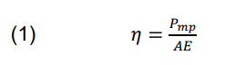
with Pmp – the module maximum power, A and E – the module total area and STC-incident irradiance, respectively. Drawings of both substrates are depicted in Figure 1. As seen, the substrates are rectangular, with no protruding parts, which saves space when installed on the roof and reduces production costs. The EFLEX 200B (P4) model no longer includes mounting holes due to fixing with adhesive tape. The current sketches of modules are depicted in Figure 1. These adjustments did not affect the architecture of P2 device from paper [17]. The structure of P4 was, however, modified by removing the additional strength layer unnecessary in the case of utilization on flat surfaces. With new components available on the post-COVID market, the structures of both devices are as in Figure 2. Please note, such a treatment makes the P4 more price-attractive for a customer needing modules exclusively for a flat roof.


For further optimisation of production costs, from the current market offer, Sunpower E66 Me3 IBC cells with declared power between 3.49 and 3.76 Wp [20] were selected. In order to find the cost-effective power (CEP) of a single-cell, a test module with 66 such cells connected in series was manufactured using the same top layer as for ESTARK-220B and EFLEX-200B (see Figure 2). Next, the maximum power at STC of the test device was measured as high as 241.8 Wp which in turn determined the CEP of 3.66 Wp. Note that this value is very close to 3.625 Wp i.e. the average power from the range given in [20]. The CEP of 3.66 Wp was then adopted for the production of ESTARK220B and EFLEX-200B. Since the power of a single cell ranges between 3.49 and 3.76 Wp, the power of the test module changes by ±3.7%. Therefore, the ±5% tolerance of CEP was assumed for ESTARK-220B and EFLEX-200B production processes.
It should be finally noted here that adjustments described above did not affect the five-steps lamination process for both modules as well as the course of manufacturing cycle described in [17].
Parameters and purpose of the ESTARK-220B and EFLEX-200B modules
The purpose and parameters of optimised devices are summarised in Tables 2 and 3.
Table 2. Modules description and purpose
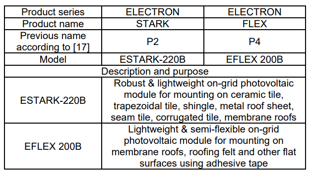
Table 3. Parameters of the modules prepared for production

Due to mechanical features of the structure the ESTARK-220B is a non-bendable but highly robust module for application on various types of roofing with the use of standard aluminium fixing systems. The EFLEX-200B is in turn dedicated for various roof surfaces, pitched and flat, for mounting without dedicated support structures, using adhesive tapes or glue. Its semi-flexibility, however, makes it possible to mount them with bending radius exceeding 5 m (see Table 2).
The models offer the peak power of 220 and 200 Wp with efficiency higher than 20%. The weight of 3.5 and 3.2 kg make them suitable for applications on roofs with low-load capacity, e.g., on production halls, supermarkets, farms, etc. This allows to avoid expensive structural reinforcement usually required prior to applying conventional heavy PV modules. The list of parameters is shown in Table 3.
This work was financially supported by Polish National Center for Research and Development under grant POIR.01.01.01-00-0050/17.
REFERENCES
[1] World Energy Outlook 2021, IEA (2021). https://www.iea.org/reports/world-energy-outlook-2021 (accessed May 30, 2022)
[2] Rynek Fotowoltaiki w Polsce 2022, Instytut Energetyki Odnawialnej, 2022. https://ieo.pl/pl/raport-rynek-fotowoltaiki-wpolsce-2022 (accessed June 30, 2022)
[3] Jäger-Waldau A., PV Status Report 2019, European Commission, Joint Research Centre, Luxembourg, (2019). https://ec.europa.eu/jrc/en/publication/eur-scientific-andtechnical-research-reports/pv-status-report-2019 (accessed May 2, 2020)
[4] Sawicka-Chudy P., Cholewa M., Sibiński M., Pawełek R., Analiza parametrów modułów fotowoltaicznych stacjonarnych i nadążnych w warunkach rzeczywistych, Przegląd Elektrotechniczny, 9 (2016), https://doi.org/10.15199/48.2016.09.15
[5] Matuszczyk P., Popławski T., Flasza J., Analiza parametrów elektrycznych systemów fotowoltaicznych różnych typów w warunkach rzeczywistych, Przegląd Elektrotechniczny, 1 (2017) 169–172, https://doi.org/10.15199/48.2017.01.41
[6] Klugmann-Radziemska E., Degradation of electrical performance of a crystalline photovoltaic module due to dust deposition in northern Poland, Renew. Energy, 78 (2015) 418– 426, http://dx.doi.org/10.1016/j.renene.2015.01.018
[7] Świderski M., Gwóźdź M., Wpływ efektu zacienienia na pracę elektrowni solarnej z systemem rozproszonych paneli fotowoltaicznych, Przegląd Elektrotechniczny, 7 (2020), https://doi.org/10.15199/48.2020.07.14
[8] Ferroni F., Hopkirk R.J., Energy Return on Energy Invested (ERoEI) for photovoltaic solar systems in regions of moderate insolation, Energy Policy, 94 (2016) 336–344
[9] Martins A.C., Chapuis V., Virtuani A.,. Li H.-Y, Perret-Aebi L.- E., Ballif C., Thermo-mechanical stability of lightweight glassfree photovoltaic modules based on a composite substrate, Sol. Energy Mater Sol. Cells, 187 (2018) 82–90, https://doi.org/10.1016/j.solmat.2018.07.015
[10] Martins A.C., Chapuis V., Virtuani A., Perret-Aebi L.-E., Ballif C., Hail resistance of composite-based glass-free lightweight modules for building integrated photovoltaics applications, in: Proceedings of the 33rd European Photovoltaic Solar Energy Conference and Exhibit, Amsterdam, The Netherlands, (2017), 2604–2608, https://doi.org/10.4229/EUPVSEC20172017-6BV.3.62
[11] Berger K., Cueli A.B., Boddaert S., Del Buono M., Delisle V., Fedorova A., Frontini F., Hendrick P., Inoue S., Ishii H., Kapsis C., Kim J.-T., Kovacs P., Chivelet N.M., Maturi L., Machado M., Schneider A., Wilson H.R., International definitions of BIPV, IEA Photovoltaic Power Systems Programme (2018), https://iea-pvps.org/key-topics/international-definitions-of-bipv/(accessed May 11, 2021).
[12] Kurz D., Nawrowski R., Kałuża S., Analysis of changes in electrical parameters of photovoltaic roof tiles depending on the place of shading and connection configuration, Przegląd Elektrotechniczny, 7 (2022), https://doi.org/10.15199/48.2022.07.21
[13] Olson C., Geerligs B., Goris M., Bennett I., Clyncke J., Current and future priorities for mass and material in silicon PV module recycling, in: Proceedings of the 28th European Photovoltaic Solar Energy Conference and Exhibition, Villepinte, France (2013) 4629–4633, https://doi.org/10.4229/28thEUPVSEC2013- 6BV.8.2
[14] Chen B.-M., Peng C.-Y., Porter G.A., Optimization of solar module encapsulant lamination by optical constant determination of ethylene-vinyl acetate, Int. J. Photoenergy, 2015 (2015) 1–7, 276404, https://doi.org/10.1155/2015/276404
[15] Martins A.C., Chapuis V., Virtuani A., Ballif C., Light and durable: Composite structures for building-integrated photovoltaic modules, Prog. Photovolt. Res. Appl, 26 (2018) 718-729, https://doi.org/10.1002/pip.3009
[16] . Martins A.C, Chapuis V., Virtuani A., Ballif C., Robust glassfree lightweight photovoltaic modules with improved resistance to mechanical loads and impact, IEEE J. Photovolt., 9 (2019) 245–251, https://doi.org/10.1109/JPHOTOV.2018.2876934
[17] Grygiel P., Tarłowski J., Prześniak-Welenc M., Łapiński M., Łubiński J., Mielewczyk-Gryń A., Mik K., Bartmański M., Pelczarski D., Kwiatek M., Prototype design and development of low-load-roof photovoltaic modules for applications in on-grid systems., Sol. Energy Mater. Sol. Cells, 233 (2021) 111384, https://doi.org/doi.org/10.1016/j.solmat.2021.111384
[18] Mik K., Zawadzki P., Tarłowski J., Bugaj M., Grygiel P., Bykuć S., Multifaceted analyses of four different prototype lightweight photovoltaic modules of novel structure, Energies, 14 (2021) 1–16, https://doi.org/10.3390/en14082239
[19] Luque A., Hegedus S., (Eds.), Handbook of Photovoltaic Science and Engineering, John Wiley & Sons Ltd, Chichester, England, 2003.
[20] Technical product datasheet of Maxeon Gen III Solar Cells, 519452 Rev.D
Authors: dr inż. Piotr Grygiel, Institute of Physics and Applied Computer Science, Faculty of Applied Physics and Mathematics, Gdańsk University of Technology, Narutowicza 11/12, 80-233, Gdańsk, Poland, E-mail: piotr.grygiel@pg.edu.pl , Xdisc S.A., Jagiellońska 82, 03-301, Warsaw, Poland, mgr inż. Jan Tarłowski, Xdisc S.A., Jagiellońska 82, 03-301, Warsaw, Poland, E-mail: jan.tarlowski@x-disc.pl, mgr inż. Krzysztof Mik, Energy Conversion and Renewable Resources Research Centre, Polish Academy of Sciences, The Szewalski Institute of Fluid-Flow Machinery Polish Academy of Sciences, Fiszera 14, 80-231, Gdańsk, Poland, E-mail: kmik@imp.gda.pl
Source & Publisher Item Identifier: PRZEGLĄD ELEKTROTECHNICZNY, ISSN 0033-2097, R. 99 NR 2/2023. doi:10.15199/48.2023.02.09
