Published by 1. Róbert Štefko1, Zsolt Čonka1, Michal Kolcun, 2. Viktor Jurák2, 3. Judith Pálfi3, Technical University of Košice (1), Brno University of Technology (2), Óbuda University (3) ORCID: 1. 0000-0002-2477-4559, 0000-0001-6620-4354, 0000-0002-8041-9076; 2. 0000-0002-6832-7654
Abstract. The penetration of renewable energy sources into the electricity distribution network causes changes in power flows, making conventional protection no longer effective. Research suggests that the solution should be the massive deployment of phasor measurement units and a centralised control, monitoring and protection system. But is this system sufficiently ready for widespread deployment in practice? While research on the decentralised system is progressing further while linking it to microgrid applications is less common.
Sreszczenie. Wnikanie odnawialnych źródeł energii do sieci dystrybucyjnej energii elektrycznej powoduje zmiany w przepływach mocy, sprawiając, że konwencjonalne zabezpieczenia przestają być skuteczne. Badania sugerują, że rozwiązaniem powinno być masowe rozmieszczenie jednostek pomiaru fazorów oraz scentralizowanego systemu kontroli, monitorowania i ochrony. Ale czy ten system jest wystarczająco gotowy do szerokiego zastosowania w praktyce? Podczas gdy badania nad systemem zdecentralizowanym postępują dalej, łączenie go z aplikacjami mikrosieciowymi jest mniej powszechne. (Badania komunikacji przekaźników ochronnych dla mikrosieci i aktywnych sieci dystrybucyjnych)
Keywords: microgrid, mutual communication, protection relay, phasor measurement unit, merging unit.
Słowa kluczowe: mikrosieć, wzajemna komunikacja, przekaźnik zabezpieczający, zespół pomiaru fazorów, jednostka scalająca.
Introduction
Active participation of consumers in the production of electricity and thus in the control of the electricity grid, mainly through the use of photovoltaic panels. Their annual increase will reach a point where the current protection system is no longer sufficient. For this reason, changes will be needed, especially in the distribution network, which will be most affected by these changes. The researchers therefore ask the question: What system will be applied to protect distribution networks and microgrids? Current research suggests that both centralized and decentralized systems offer opportunities for deployment in microgrids. When considering a decentralized system, the transmission requirements for communication between individual protection relays decrease significantly. Since the intercommunication is only between certain protective relays and even then only in small data volumes that do not require such a robust communication network. In contrast, a centralized system necessarily requires a massive communication infrastructure by which the network or system will be controlled. Thus, the mutual communication will not take place between the individual protection relays with each other but only through the central control logic, which will evaluate the status according to the received measured data. The measured data will be sent by the measuring units according to the selected sampling frequency continuously, whereby the loss of a few data packets can significantly disturb the system, which can then misjudge the situation and thus act inappropriately. Real-time control systems are very sensitive to the loss or delay of received data (packets) [1]. The time delay in such a case is a period of more than 500ms.
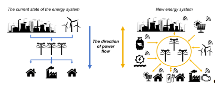
The significant development of digital technologies has not only influenced the progress made in control and protection but still possessed one shortcoming and that is the conventional way of reasoning, which is not sufficient for the new installed switching power sources and for the placement of the sources close to the consumption. The power flow changes from forward to reverse as well as shown in Fig. 1 [2].
WAMS (wide area measuring system)
This new centralised system brings new possibilities in the areas of management, monitoring and protection. The system uses phasor measurements that are linked to GPS time by communicating with at least four satellites. Thus, the measured values are synchronized with the GPS clock, thus creating the space for real-time monitoring of a large area and the stability of the system. Currently, this measurement unit known as PMU (Phasor Measurement Unit) is used as an independent measurement unit and currently this measurement unit can also be found implemented in the protection relays themselves, while its functions are separated from the protection system. For the use of such a measurement in a protection system, the complexity increases in the application and with this arises a number of problems that still need to be solved [3].
The principle of operation of a centralized protection system is basically simple. PMUs provide processing and sending of measured data from potentional transformer (PT), current transformer (CT) and sensors. This unit delivers the signal of the phasor data concentrator (PDC) via the optical network. This is where the problem arises since such a unit will receive many such signals it must be powerful enough which is no longer a problem with today’s computing technology. The problem is that if we consider at least five such units in one substation and the managed area will have dozens of stations, the transmission capacity of the network may not be sufficient. Network congestion will cause packet delivery delays. However, if this problem is solved, the PDC will deliver the data to the central unit (server) for further processing according to the given algorithm and evaluate the current status and the necessary actions.
Communication protocols used for data transmission
Synchronized phasors use the IEEE C37.118.2 standard for data transmission. PMUs protocol use four types of frames: DATA, CONFIGURATION, HEADER, and COMMAND.
The DATA frame consists of measured phasors, states (loss of measured value), and other measured parameter with time stamp. The CONFIGURATION frame contains details for data processing such as: calibration data, data type, and other metadata.
The HEADER frame consists of descriptive information related to the PMU sent to the PDC.
The COMMAND frame contains the command (code) to control or configure the PMU or PDC [3, 4]. Protection systems use the IEC 61850 standard for their functionality, which is designed for intercommunication. The protocol uses four types of frames: CONFIGURATION, EVENT, MMS, COMMUNICATION.
The CONFIGURATION frame is used to select the data to be sent.
The EVENT frame is used for logging. The MMS frame is used for establishing the actual communication between the individual protective relays of the contents of the address of the destination protective relays only.
The COMMUNICATION frame is commonly used for communicating with each other and for sending and receiving data [3].
The characteristics of the transmission media play an important role in power grid communication infrastructure. Power grid transmission media are classified into two main group: dependent and independent ones. Dependent media are part of power network elements, i.e., power line communication (PLC), broadband over power line (BPL), optical power ground wire (OPGW), and all-dielectric selfsupporting (ADSS). In contrast, independent media do not depend on the power system and may be of the type available to all users as an open access media (for instance, wireless communication media) or those owned by data service providing companies (such as leased line or dedicated data links) [5].
Power Line Communication (PLC)
The use of power line communication for microgrids is unrealistic for several reasons. One of the main drawbacks is the need for short distances for acceptable signal quality. The transmission lines themselves, due to the use of various loads, contain considerable noise which significantly reduces the signal quality. The maximum transmission rate is around 2 to 3 Mbps [7]. Whereby a transmission capacity of 2 Mbps is not sufficient to provide adequate delay for 8 PMUs transmitting at 30 FPS [6].
Optic Fiber Communication
The use of optical fibre has brought the advantage of mainly long-distance communication transmission bandwidth while providing high reliability, low attenuation, and higher transmission speeds with less interference. The main disadvantage is the relatively difficult construction of such communication infrastructure along with high investment costs [7]. The transmission speed of such light technology is around tens of Gbps.
Cellular Network Communication
The use of wireless communication technology brings advantages in the form of applications, but it is necessary to guard the quality of the signal so that there can be no communication failure. Currently, there are mainly two mobile technologies for use as long term evaluation advanced (LTEA) and high-speed packet access (HSPA). The transmission rate of LTEA is above 100 Mbps and that of HSPA is in the range of 600 kbps to 10 Mbps [7].
The following chapters will focus on the centralized system and the emerging issues related to PMUs and the impacts causing packet delay in the centralized system.
Communication networks and impacts on PMUs
A university project from Universidade Federal is examining the network operation of six PMUs, hundreds of meters and twelve power quality analysers, and data from a weather station. The subject was the detection of delay time and packet loss. The data was transmitted using datagram protocol (UDP) in low latency mode at 120 FPS in IEEE C37.118 format. Each data frame contained 8 measurements: voltage and current amplitude and angle for each phase of the three-phase system, frequency, and rate of change of frequency (ROCOF). Fig. 2 shows the considered network connection [8].
Table 1 shows the measured communication delay times between the server and the PMU and the PDC. The measured results show that the transition through the router towards the switch has more than twice the response time.

Table 1. Delay in communication from server to PMU and PDC [8].

The PMUs that were connected to the local VLAN had a small packet loss ratio of 1.1×10⁻⁵ while the same results were obtained over the research network (RNP). PMU 4 which was in a different campus showed a higher packet loss ratio of 9.63×10⁻⁵. Here, the assumption of link complexity depending on the increasing number of devices and the impact on possible delays and packet losses was confirmed [8].
In the paper [10] by H. Lin et al. the study confirmed that the importance of the communication infrastructure will be crucial for the deployment of PMUs and their wide range of applications for both trail management and protection and monitoring. They concluded that if the network is only used for measuring synchro phasors, the system does not require very high bandwidth. But the problem arises when other communication links besides measurement are transmitted over the same switching network, then packet loss starts to increase sharply, and the system becomes unstable.
PMU placement optimization technique
PMU placed at network bus, record and capture the bus voltage phasor at that bus and current phasors along all branches that are incident to that bus. Rules for determining power system observability topologically are as mentioned below [9]:
1. For a PMU installed bus, voltage phasor of that bus and currents phasors of all incident branches to that bus are known.
2. If voltage and current phasors at one end of a branch are known, then voltage phasor at the other end of that branch can be obtained using Kirchhoff’s voltage law.
3. If voltage phasors of both ends of a branch are known, then the current phasor of this branch can be obtained directly using Kirchhoff’s current law.
The objective of PMU placement problem is to find the minimum number of PMUs as well as their placement to make the power network topologically observable [9].
This paper describes an optimal placement method using binary integer programming in MATLAB for PMU and PDC placement for minimum number of units and communication distance of units. Experimentally, the calculation has been carried out for IEEE 14 (14 buses) and IEEE 30 (30 buses) system [9].
Table 2. PMU and PDC placement results [9].

The results confirm that for a successful observability of the system, it is necessary to place one third of the number of PMUs to the total number of buses of the system and half of the PDC units to the number of placed PMUs. Which significantly reduces the total investment cost of building such a new way of controlling, protecting, and monitoring the power system.
Security mechanism for PMU communication
The current widely used communication standard for PMUs according to IEEE C37.118.2, but which does not specify or propose any security method to protect PMU data from attacks. A cyber-attack may aim at causing a deviation of the transmitted data which may lead to network failure and consequently to high economic damages. Hussain S.M.S et al. In [9] proposed and tested a simple method to secure the communication between PMU and PDC. The application does not require robust computational power nor does this addition significantly increase the volume of data transmitted.

Likewise, Sukumara T. et al. in [11] and [12] by R. Pramudit et al. propose a way to secure PMU messages by introducing a TLS layer to each device according to the available security techniques, stressing that developments in this area must not lose importance and must continue to progress vigorously.
Loss of PMUs measurement and impact on the protection system
The practical deployment of PMUs has discovered several problems that were not anticipated in the floods. One of them is just the loss of PMU measurements and the reason for the loss of measurements is not a problem in the communication itself but the loss of the GPS signal to synchronize the measured data from the network. However, recent studies have shown that PMU GPS signals are often lost due to factors such as weather events and communication failures, resulting in the loss of PMU measurements. The occurrence of such PMU measurement losses has been recorded up to several times per day, with each loss ranging in time from 7 seconds to more than 25 seconds. In WAMPAC applications, loss of GPS signal for the PMU has been shown to lead to severe degradation of system performance. In addition, control strategies that rely on PMU measurements have been shown to be vulnerable to GPS spoofing attacks, in which a falsified GPS signal can be fed to compromise the PMU measurement, leading to potentially catastrophic consequences and cascading failures. Therefore, consideration needs to be given to how such losses can be mitigated in the future. One simple solution is that in the event of GPS loss, the time will be automatically re-calculated. When the connection is reestablished, the time will be synchronized again o continue to measure accurately, since the loss of signal is in the range of a few tens of seconds. Is this off-line temporary solution an acceptable substitute [13].
The following chapters will focus on decentralized systems and prospectively applicable current devices used in distribution networks.
Use of directional protectors in microgrids
Protecting distribution networks with directional overcurrent protectors, when applied appropriately, can cause a significant reduction in tripping time during a fault condition. The applicability of such protection will be influenced by the mode of operation of the transformer node as well as the local applied power sources in the area. The creation of a microgrid based purely on switched-mode sources is not feasible. Which simplifies the fault current magnitude issue somewhat since switching sources have a marginal short circuit current contribution. Of course, the topology itself and the placement of the individual sources in it will also influence the fault current.
Significant reduction of the tripping time is achieved just by using directional protectors at both ends of the protected section. However, a reliable communication system will be a necessity in such an application, as the communication of these relays with each other is essential as shown in Figure 4 and Figure 5. This will reduce the tripping time to one common delay.

For a correct evaluation of the directionality, it will depend on the evaluation algorithm used from the measured data. The traditional method of evaluating directivity by comparing the voltage versus current phasor may not always evaluate correctly. Whereby, research indicates the reliability of using directional routing according to the direction of reactive power.
As a transmission medium, the use of fiber optics is currently a relatively high standard. IEDs use the IEEE 61850 standard for peer-to-peer communication and the widely applied GOOSE protocol for peer-to-peer communication. To bring the IED into operation for both ends of the line, they are interconnected and bound in the algorithm by a common condition for the trip stimulus. A similar scheme was considered in the paper [14] by H.M. Sharaf et al. and paper [15] by M. Yalla et al.
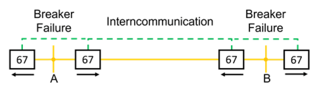
When one of the IEDs fails to shut down, a Breaker Failure message is sent using the GOOSE protocol to the closest IED in the substation, which will provide a backup shutdown. The selectivity of the tripping is ensured only through mutual communication. In paper [16], authors J.A. Ocampa-Wilches et al. evaluate the effect of directional overcurrent protection for different states and fault locations in a simple IEEE model of a 5-bus network.
In the paper, the authors evaluate the resulting action, which is located only on one side of the line, causing load 2 to be disconnected. For this reason, this basic concept was extended for bidirectional action and mutual communication thus achieving the same scheme to feed load 2 even in the case of fault F.3. The outlet to the external load and load 1 would have the same concept as considered by the authors of the paper [16].
Use of differential protection in microgrids
In contrast to directional overcurrent protections, differential protections are much more sensitive to change and thus, when protecting distribution lines, mainly to the loss of measurement of the other side of the line as shown in Fig. 6. Their method of evaluation is more reliable and thus their application can be counted on in microgrids. Differential protection will also react reliably at low values of short-circuit current due to its tripping characteristics and mode of operation. The protection will react if there is a minimal increase in the measured value of the current on one side of the line whereas with directional protectors it is necessary that the magnitude of the fault current is greater than the nominal current to change the phase angle of the faulted phase current.

The tripping time of differential protection versus directional protection does not change much hence the application of these IEDs achieves the same significant reduction in tripping time versus conventional tripping time. The drawback in such an application is that in case of IED failure the problem of backup protection will arise. For this reason, it is advisable that the differential protection system be supplemented with distance protection as backup protection.
A similar use will be possible in the application of PMUs, in which case the possibilities for the use of differential protection are much wider than the purely current use of deploying only one differential protection per line.
Testing the decentralised design
The functionality of directional protection relays and differential protection was tested on a model IEEE network consisting of 10 buses and 10 loops. The power supply of such a topology provided power to the network from one side and the PV station.

It confirmed the assumption evaluated in the previous sections of this paper. Differential protection successfully acted for all fault types in all considered fault locations F1- 11. Thereby, the potential of differential protection was demonstrated. While the directional protection relays were not able to provide tripping for fault locations F1 and F4 hence the need for further investigation of the given routing issue and its further application in microgrids.
Conclusion
A review of research indicates that the communication network will play a major role in the practical application of PMUs in the construction of microgrids and active distribution networks. Which type of system will eventually be used for microgrids is not yet fully clear as both methods have their significant shortcomings so far. Research on communication networks needs to be further developed not only to increase the transmission bandwidth but also from a security perspective as this paper points out. With the increase in cyber-attacks in recent years, the area of security has become a very important and hot topic for all power systems. In a centralized system, security and data transmission for individual units need to be addressed. On the other hand, in a decentralized system, it is necessary to think about how much it is still possible to apply conventional methods to a new system that has parametrically completely different requirements and dynamic happenings.
Acknowledgments – This research was funded by the Slovak Research and Development Agency [APVV-19-0576] and [APVV-21-0312] and the Ministry of Education, Science, Research and Sport of the Slovak Republic and the Slovak Academy of Sciences [VEGA 1/0757/21].
REFERENCES
[1] T I P S U W A N Y . , CHOW Y., Control methodologies in networked control systems, Control Engineering Practice, 11 (2003), no. 10, pp. 1099-1111, ISSN: 0967-0661.
[2] Š T E F K O R., ŠÁRPATAKY M., ŠÁRPATAKY L., et al., Construction and development of microgrids around the world, Elektroenergetika: International Scientific and Professional Journal on Electrical Engineering: Medzinárodný vedecký a odborný časopis pre elektroenergetiku, 15 (2022), no. 1,pp. 16-19, ISSN: 1337-6756.
[3] Z H A N G C H . , BO Z., Z H A N G B., et al., An integrated PMU and protection scheme for power systems, International Universities Power Engineering Conference (UPEC), 44 (2009), Glasgow, pp. 1-4, ISBN: 978-0-947649-44-9.
[4] H U S S A I N S . M . S . , FAROOG S.M., USTUN T.S., A Security Mechanism for IEEE C37.118.2 PMU Communication, IEEE Transactions on Industrial Electronics, 69 (2022), pp. 1053-1061, ISSN: 1557-9948.
[5] S H A H R A E I N I M . , HOSSEIN J.M., SADEGH G.M., Comparison Between Communication Infrastructures of Centralized and Decentralized Wide Area Measurement Systems, IEEE Transactions on Smart Grid, (2011), pp. 206-211, ISSN: 1949-3053.
[6] C H E N I N E M . , KHATIB I.A., IVANOVSKI J., et al., PMU Traffic Shaping in IP-Based Wide Area Communication, Proceedings of the 5th International Conference on Critical Infrastructure (CRIS), 5 (2010), pp. 1-6, ISBN: 978-1-4244-8081-4.
[7] G H O S H S . , CHANDAN KR.CH., D A S J.K., et al., A Comprehensive Survey on Communication Technologies for a Grid Connected Microgrid System, International Conference on Artificial Intelligence and Smart Systems (ICAIS), (2021), Coimbatore, pp. 1525-1528, ISBN: 978-1-7281-9537-7.
[8] P O L E D N A Y . , PEREIRA J.L., RIBEIRO E.P., Network traffic analysis of micro-PMU communication at university campus, Workshop on Communication Networks and Power Systems (WCNPS), (2019), pp. 1-4, ISBN: 978-1-7281-2920-4.
[9] B H O N S L E J . S . , JUNGHARE A.S., An optimal PMU-PDC placement technique in wide area measurement system, International Conference on Smart Technologies and Management for Computing, Communication, Controls, Energy and Materials (ICSTM), (2015), pp. 401-405, ISBN: 978-1-4799-9855-5.
[10] L I N H . , S A M B A M O O R T H Y S . , S H U K L A S . , e t a l . , A study of communication and power system infrastructure interdependence on PMU-based wide area monitoring and protection, IEEE Power and Energy Society General Meeting, (2012), pp. 1-7, ISBN: 978-1-4673-2729-9.
[11] S UK UMA RA T . , STARCK J., KUMAR E., et al., Cyber security – Securing the protection and control relay communication in substation, 71st Annual Conference for Protective Relay Engineers (CPRE), 71 (2018), pp. 1-7, ISSN: 2474-9753.
[12] P R A M U D I T A R . , H A R I A D I F . I . , A C H M A D A . S . , Development of IoT authentication mechanisms for microgrid applications, International Symposium on Electronics and Smart Devices (ISESD), (2017), pp. 12-17, ISBN: 978-1-5386-2778-5.
[13] S I V A R A N I A N I S . , A G A R W A L E . , G U P T A V . , e t a l . , Distributed Mixed Voltage Angle and Frequency Droop Control of Microgrid Interconnections with Loss of Distribution- PMU Measurements, IEEE Open Access Journal of Power and Energy, 8 (2021), pp. 45-56, ISSN: 2687-7910.
[14] S H A R A F H . M . , ZEINELDIN H.H., EL-SAADANY E., Protection Coordination for Microgrids with Grid-Connected and Islanded Capabilities Using Communication Assisted Dual Setting Directional Overcurrent Relays, IEEE Transactions on Smart Grid, 9 (2018), pp. 143-151, ISSN: 1949-3061.
[15] Y A L L A M . , A D A M I A K M . , A P O S T O L O V A . , e t a l . , Application of peer-to-peer communication for protective relaying, IEEE Transactions on Power Delivery, 17 (2002), pp.446-451, ISSN: 1937-4208.
[16] O C A M P A – W I L C H E S J . A . , USTARIZ-FARFAN A.J., Cano-Plata E.A., Modeling of a Comunications-Based Directional Overcurrent Protection Scheme for Microgrids, IEEE ANDESCON, (2018), pp. 1-6, ISBN: 978-1-5386-8372-9
Authors: Ing. Róbert Štefko, Technical University of Košice, Department of Electric Power Engineering, st. Mäsiarska 74, 040 01 Košice, Email: robert.stefko@tuke.sk; 236 PRZEGLĄD ELEKTROTECHNICZNY, ISSN 0033-2097, R. 99 NR 7/2023 doc. Ing. Zsolt Čonka, PhD., Technical University of Košice, Department of Electric Power Engineering, st. Mäsiarska 74, 040 01 Košice, E-mail: zsolt.conka@tuke.sk; Dr. h.c. prof. Ing. Michal Kolcun, PhD., Technical University of Košice, Department of Electric Power Engineering, st. Mäsiarska 74, 040 01 Košice, E-mail: michal.kolcun@tuke.sk; Ing. Viktor Jurák, Brno University of Technology, Department of Electric Power Engineering, st. Technická 12, 61 600 Brno, E-mail: xjurak04@vut.cz. Dr. Judith Pálfi, Óbuda University, Department of Electric Power Engineering, 1034 Budapest, Bécsi út 96/B, E-mail: palfi.judith@kvk.uni-obuda.hu.
Source & Publisher Item Identifier: PRZEGLĄD ELEKTROTECHNICZNY, ISSN 0033-2097, R. 99 NR 7/2023. doi:10.15199/48.2023.07.43
