Publishd by Ahmed A. Abdullah AL-KARAKCHI1, Enaam ALBANNA2, Alya H. AL-RIFAIE3, Northern Technical University (1,2,3) ORCID: 1. 0000-0003-1151-3015; 2. 0000-0002-3974-0116; 3. 0000-0002-7978-2193
Abstract. Unbalanced network voltage damages utility and end-user equipment. Electrified trains, single-phase distributed generators, and line-toline connected industrial loads can increase voltage imbalances. Using Dynamic Voltage Restorer (DVR) at appropriate places is one way to reduce imbalance in practical networks. This research proposes a new technique for managing DVR to improve voltage profile. The simulation results imply that real-time implementation of the suggested controller is practical and resilient.
Streszczenie. Niezrównoważone napięcie sieciowe uszkadza sprzęt komunalny i użytkownika końcowego. Zelektryfikowane pociągi, jednofazowe rozproszone generatory i obciążenia przemysłowe połączone między liniami mogą zwiększać nierównowagę napięcia. Używanie dynamicznego przywracania napięcia (DVR) w odpowiednich miejscach jest jednym ze sposobów zmniejszenia asymetrii w praktycznych sieciach. Badanie to proponuje nową technikę zarządzania DVR w celu poprawy profilu napięcia. Wyniki symulacji sugerują, że implementacja sugerowanego kontrolera w czasie rzeczywistym jest praktyczna i odporna. (Dynamiczny przywracacz napięcia do ograniczania asymetrii napięcia i poprawy profilu napięcia w sieci dystrybucyjnej)
Keywords: DVR, Voltage unbalance, voltage profile, p-q Theory, Fuzzy Logic.
Słowa kluczowe: nierównowaga napięć, dynamiczne przywracanie napięciea.
Introduction
The electric power system is a network that transmits, supplies, and distributes electricity using electrical components. The three major components of power systems are generation, transmission, and distribution, which provide power to nearby residential complexes and large industries [1]. The network consists of three phases, which are three current and voltage signals (peak value) of equal magnitude but shifted by 120o as a phase difference between phases. If either the magnitude or the phase shift, or both, do not meet the standard, this is referred to as unbalance condition. In the majority of cases, the world’s modern power system uses AC three-phase power in a typical large-scale configuration for power transmission and distribution [2][3]. Single-phase loading is the leading cause of voltage unbalance. Line voltage unbalance caused by asymmetry of either current or voltage or both asymmetry of current and voltage at the same time [3]. Voltage unbalance is the most commonly occurring problem in power quality cases today, particularly in low voltage distribution systems. Voltage unbalance is the maximum amplitude phase voltage deviation from the average nominal phasemagnitude voltage [4]. In a similar way, voltage unbalance—which is also regarded as power quality—is described in [5] as the ratio of the difference between the greatest and smallest amplitudes of phase voltage magnitude to the mean phase-magnitude voltage. The power quality delivered to end users can be estimated as a constant magnitude of voltage, which means balanced in phases, zero voltage deviation, around unity power factor, fixed frequency, no variation in voltage like sags swells conditions, no any interruptions in power supply and also the ability to protect and isolate faults very quickly. The application of a new design controller in a distribution system to provide high reliability of an electrical power system to end users, which has increased the industry’s standing in the deregulated power network around the world. The following are the primary causes of voltage unbalance [6]: 1. The parameters of both the distribution and transmission lines, as well as the generators, are unsymmetrical [7]. Unbalanced voltages will result if the consumer load on one or two phases differs from the load on three phases. 2. An unbalanced current that passes through the system impedance causes an unbalanced voltage drop. 3. Transformer banks in open delta connection. 4. The faults in power transformer. 5. The power supply unsymmetrical impedance conductors. On the load side, the effect of voltage unbalance in equipment can be explained as follows [8]:
1. Voltage unbalance in rotating machines causes a reverse magnetic field, which causes torque to decrease due to heating of machine windings [9].
2. Damaging the power supply’s wiring (generators and transformers).
3. Unbalanced voltages at the terminals of a motor result in an unbalanced phase current of 6 to 10 times the motor’s full load.
4. It also reduces motor torque capability.
For many years, numerous techniques, including series capacitors, shunt reactors, boosting transformers, and, most recently, the VAR compensator “reactive power compensation,” have been utilized in the industrial sector for compensating voltage unbalance in electric distribution systems. Many researchers have proposed various mitigation techniques for correcting variation in line voltage and improving the voltage profile in the distribution network; This involves adjusting the medium feeder voltage, rearranging the phases, and balancing the phases between the distribution energy converter banks and the radial layout of the distribution system [5]-[10].
The previously mentioned techniques primarily target the medium and low voltage sides of the distribution network. However, Consumers and the power company were hoping for more efficient solutions to problems of voltage variation and voltage profile improvement, but the proposed ones were actually less effective.
Dynamic Voltage Restorer
The DVR provides three-phase controllable voltage in amplitude and phase shift (vector), which adds to the line voltage to restore the voltage in the load side to pre-disturbance levels, as illustrated in Figure (1) [11].
DVR is comprised of signal control, measuring parameters, and a power unit. Figure (2) [12] depicts the main components:


The following are the three types of DVR control strategies [13]:
• In-phase
• Pre-Sag
• Minimum Energy
All of these strategies for compensating line voltage are depicted in Figure 3 [14].

The DVR injects the line voltage by adding a voltage with an adjustable amplitude and phase shift in series with it., regardless of its magnitude and phase angle. As a result, the voltage after DVR will be the sum of the line voltage and the DVR voltage VDVR, as shown below:

The DVR voltage can increase or decrease magnitude and phase voltage by reversing the voltage polarity of VDVR (180° phase-shifted). Depending on the above strategies, the DVR voltage can add amplitude only, amplitude and phase shift, or voltage amplitude and phase shift depends on minimum energy. The second type of strategy used in this proposed design was in-phase compensation, in which the controller checks the amplitude and phase angle of the line voltage to inject the compensated voltage. It is also worth noting that the DVR has a quick response time of less than a cycle, allowing it to track the line voltage and compensate in abnormal conditions [15].
Measuring the Line Voltage
Instantaneous power theory, also known as p-q theory, was used for quick response when measuring line voltage. Akagi et al. developed this theory in 1983 with the goal of applying it for measuring and controlling active and reactive power for power flow control or filtering. P-q theory is based on Time Domain, and it can be applied in both steady-state and transient-state conditions. It can also be applied directly to instantaneous voltage and current waveforms in power systems, allowing for real-time control of all power parameters such as voltage, current, active power, and reactive power. This theory’s main advantage is its simplicity and clarity in calculations, which require only algebraic calculations with the exception of separating alternated and mean power values. The p-q theory is implemented using the Clarke Transformation for a stationary reference, which eliminates the need for an angle ad in d-q or abc transformations. This transformation is performed from a-b-c coordinates to α-β-0 coordinates and vice versa [16].The DVR voltage can increase or decrease magnitude and phase voltage by reversing the voltage polarity of VDVR (180° phase-shifted). Depending on the above strategies, the DVR voltage can add amplitude only, amplitude and phase shift, or voltage amplitude and phase shift depends on minimum energy. The second type of strategy used in this proposed design was in-phase compensation, in which the controller checks the amplitude and phase angle of the line voltage to inject the compensated voltage. It is also worth noting that the DVR has a quick response time of less than a cycle, allowing it to track the line voltage and compensate in abnormal conditions [15]. Measuring the Line Voltage Instantaneous power theory, also known as p-q theory, was used for quick response when measuring line voltage. Akagi et al. developed this theory in 1983 with the goal of applying it for measuring and controlling active and reactive power for power flow control or filtering. P-q theory is based on Time Domain, and it can be applied in both steady-state and transient-state conditions. It can also be applied directly to instantaneous voltage and current waveforms in power systems, allowing for real-time control of all power parameters such as voltage, current, active power, and reactive power. This theory’s main advantage is its simplicity and clarity in calculations, which require only algebraic calculations with the exception of separating alternated and mean power values. The p-q theory is implemented using the Clarke Transformation for a stationary reference, which eliminates the need for an angle ad in d-q or abc transformations. This transformation is performed from a-b-c coordinates to α-β-0 coordinates and vice versa [16].
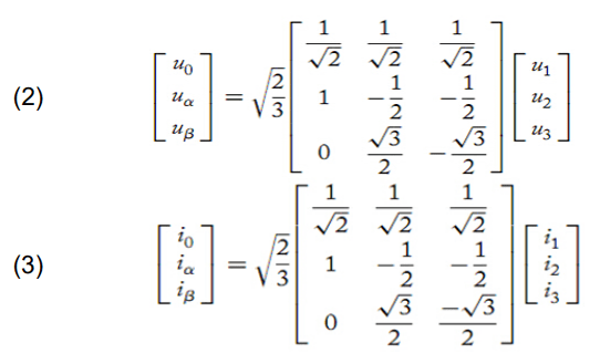
The two parameters p (active power) and q (reactive power) are then calculated as follows:

Where iα and iβ are orthogonal current, and vα and vβ are orthogonal voltage. The voltage after compensation is as follows:

To get phase voltage:

Voltage unbalance is calculated using the Maximum Deviation Method (MDM), and the voltage unbalance carried on by an unbalanced main load [17] is given: Voltage unbalance%= (MAX Deviation from V) ̸ Ṽ

Where v1, v2 and v3 are the phase voltage readings.
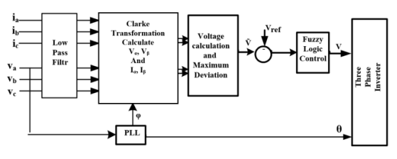
DVR Control Design
Figure 4 depicts the DVR control system’s block diagram structure. Line voltages and currents are measured from the line, and a filter stage was added to eliminate noise and harmonics. Clarke transformation is used to calculate the orthogonal two voltages and currents components (vα, vβ) and (iα, iβ). Equation 6 is used to calculate the compensated voltage, and the voltage unbalance is calculated using the Maximum Deviation method MDM; this voltage signal serves as feedback for the closed loop control system Fuzzy logic, where V∑ is compared to the reference voltage Vref set point of the line voltage to be compensated, and an error signal, verror, is generated.
Fuzzy Logic Control System
The Fuzzy logic control was used, which is adequate for approximate reasoning, especially in systems with mathematical model equations that are difficult to derive [18]. In this proposed study, Takagi-Sugeno TS inference mechanism systems are used. This study tunes Takagi-Sugeno ANN membership functions. Figure 5 depicts the Fuzzy logic control design. Fuzzy logic controller with adaptive learning capabilities using ANN, this approach can be easily trained, and the rule base of Fuzzy controller is reduced [19].
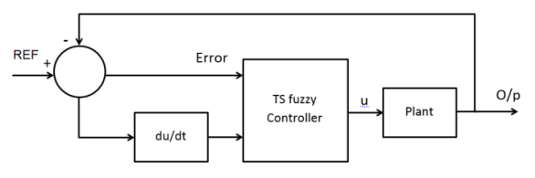
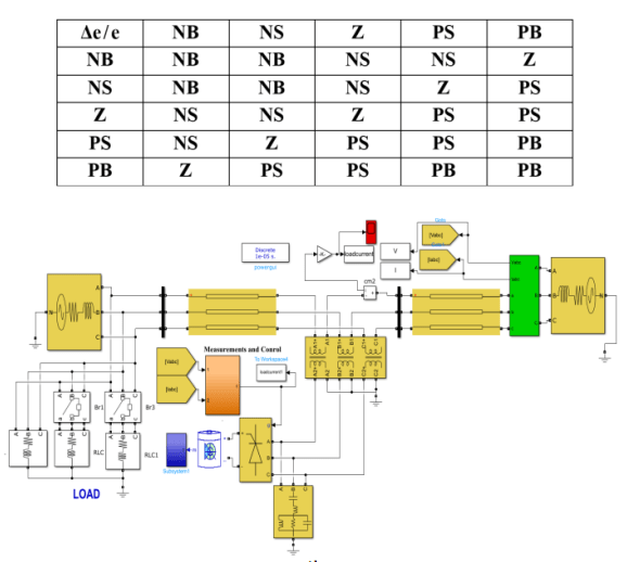
The Fuzzy control system is composed of five layers, each of which has parameters that do not require tuning (constants) or have parameters that do require tuning (variables) during the training stage. The input discourse universe is divided into five triangle form membership functions with 50% overlap, for two input signals error and Δerror, the control rule is 25 to result of linear functions as required to be set, as shown in Table 1. Figure 6 depicts the structure of the Fuzzy logic control design. Two groups of data are generated to tune the rules using adaptive fuzzy. There are two input vectors: Verror and ΔVerror, and the output is the modulation index “m.”
Simulation Study
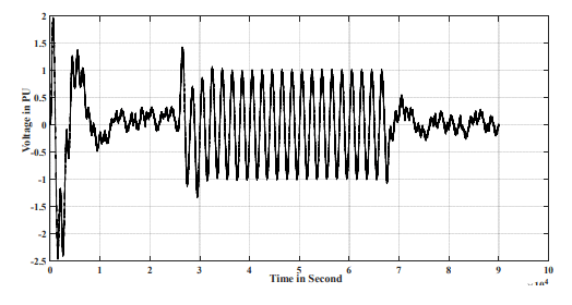
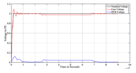
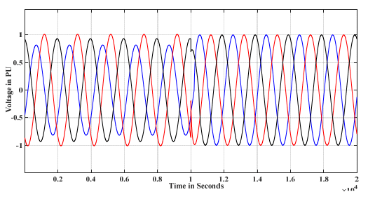
The proposed model is consisting of a low voltage feeder with a variable load and three branches for balance and unbalance load conditions. As shown in Figure 7, the DVR is connected to the load side to compensate for the load voltage. The simulation test begins by varying the three phase load, first in balance condition and measuring the line voltage, then at t=2.5 additional load add the voltage decrease as shown in Figure 8a, and compensation is done by injecting VDVR for balance load to compensate the voltage at sag condition as shown in Figure 8b. The drop in line voltage increased proportionally to the increase in load, with the maximum drop being 0.8 pu between 2.5 and 6.75 sec. Figure 9 depicts the injected voltage at the previously mentioned time interval. Figure 10 depicts the line voltage versus the DVR voltage under sag conditions. Figure 11 shows the action of the DVR at t=1 seconds and Figure 12 shows the injected compensated voltage in unbalance condition, respectively, to validate the DVR under unbalance voltage, a sudden heavy unbalance load changed. According to the results of Figures 11 and 12, the DVR has the ability to respond quickly to an unbalance condition and restore the line voltage to its nominal value.


Conclusions
In this proposed study, a DVR-based fuzzy logic controller has been installed on the load bus, and Simulations of voltage unbalance and sag condition have been used to investigate a number of abnormal conditions. The simulation results show that the action of a DVR with an adaptive controller improves the voltage profile in the distribution system and restores the voltage unbalance condition. The simulation was compared with and without compensation, as well as balance and unbalance conditions, with the balance condition for sag and the unbalance load for voltage unbalance. The DVR was able to restore the load voltage to its nominal value (within about 97%) in two conditions. The computation action time was approximately 10 msec; this response time is critical for tracking any change in real time. The simulation results in both conditions show that the Fuzzy Logic controller provides good response for the operation of the DVR.
REFERENCES
[1] Alya H. AL-RIFAIE, Sanabel M. ALHAJ ZBER, Noha Abed-ALBary AL-JAWADY, Ahmed A. Abdullah AL – KARAKCHI, “Analysis of faults on high voltage direct current HVDC transmissions system”, Przegląd Elektrotechniczny, issue. 2 pp. 49-53, FEB 2022.
[2] ZBER, Sanabel Muhson ALHAJ, et al. “Simulation and Analysis of a VSC-HVDC Transmission System Based on DC Line-Line Fault.”, Przegląd Elektrotechniczny, issue. 8 pp. 69-72, AUG 2022.
[3] T. D. Kahingala, S. Perera, U. Jayatunga, and A. P. Agalgaonkar,“Estimation of voltage unbalance attenuation caused by three-phase induction motors: An extension to distribution system state estimation,” IEEE Transactions on Power Delivery, 2019.
[4] PKapil, C. Vibhakar, S. Rajani and K. Bhayani,” Voltage Sag/Swell Compensation Using Dynamic Voltage Restorer (DVR)”, International Journal of Application or Innovation in Engineering & Management (IJAIEM), vol 4, no 3, pp 1-8, 2013.
[5] I. Afandi, P. Ciufo, A. Agalgaonkar, and S. Perera, “A combined mv and lv network voltage regulation strategy for the reduction of voltage unbalance,” in 2016 17th International Conference on Harmonics and Quality of Power (ICHQP), Oct 2016, pp. 318–323.
[6] A. Damor and V. Babaria, ” Voltage Sag Control Using DVR”, National Conference on Recent Trends in Engineering & Technology India, pp 1-4, 13-14 May 2011S.
[7] D. M. Soomro and et al “Mitigation of Voltage Sag Caused by Unbalanced Load by Using DFT Controlled DVR,” 2019 IEEE International Conference on Innovative Research and Development, 2019, pp. 1-6, 2019.
[8] M. Sharanya, B. Basavaraja and M. Sasikala,” Dynamic Voltage Restorer (DVR) for Voltage Sag Mitigation”, International Journal on Electrical Engineering and Informatics, vol 3, no 1, pp1-11, 2011.
[9] Pradhan, M., and Mishra, M. K.. Dual P-Q Theory based Energy Optimized Dynamic Voltage Restorer for Power Quality Improvement in Distribution System. IEEE Transactions on Industrial Electronics, 1–1., 2018.
[10] Mohammed Y. Suliman and Mahmood T. Al-Khayyat, . “Power flow control in parallel transmission lines based on UPFC.” Bulletin of Electrical Engineering and Informatics 9.5 (2020), pp.1755-1765.
[11] T. D. Kahingala, S. Perera, U. Jayatunga, and A. P. Agalgaonkar, “Estimation of voltage unbalance attenuation caused by three-phase induction motors: An extension to distribution system state estimation ” IEEE Transactions on Power Delivery, 2019.
[12] S. Panda, and N. P. Padh,. “Comparison of particle swarm optimization and genetic algorithm for FACTS-based controller design”, Appl. Soft Compute., vol.8, no.4, pp. 1418-1427, 2008.
[13] Harshita B., Kajol S., Navneet K. Effect of Voltage Sag and Voltage Unbalance on Induction Motor Drives. International Journal Of Advance Research, Ideas And Innovations In Technology (IJARIIT). 2017. 3(6). 258-263.
[14] Harshita B., Kajol S., Navneet K. Effect of Voltage Sag and Voltage Unbalance on Induction Motor Drives. International Journal Of Advance Research, Ideas And Innovations In Technology (IJARIIT). 2017. 3(6). 258-263.
[15] Anulal A. M, Archana Mohan and Lathika B. S, “Reactive power compensation of wind-diesel hybrid ystem using STATCOM with Fuzzy tuned and ANFIS tuned PID controllers”, International Conference on Control Communication & Computing India (ICCC), IEEE Conference,19-21 Nov,2015, pp. 325–330, 2015.
[16] Alkhayyat, M.T., Suliman, M.Y., Aiwa, F.F. ,” PQ & DQ based shunt active power filter with PWM & hysteresis techniques”, Przeglad Elektrotechnicznythis, 2021 (9), pp. 78-84, 2021, doi:10.15199/48.2021.09.17.
[17] G. Gupta and W. Fritz, “Voltage unbalance for power systems and mitigation techniques a survey,” IEEE 1st International Conference on Power Electronics, Intelligent Control and Energy Systems (ICPEICES), pp. 1-4, 2016, doi: 10.1109/ICPEICES.2016.7853717.
[18] Mohammed Y. Suliman, ” Voltage profile enhancement in distribution network using static synchronous compensator STATCOM “, International Journal of Electrical and Computer Engineering (IJECE), Vol. 10, No. 4, 2020, pp. 3367~3374.
[19] Alkhayyat, M.T., Suliman, M.Y., Aiwa, F.F., ” PQ & DQ based shunt active power filter with PWM & hysteresis techniques | Bocznikowy aktywny filtr mocy oparty na PQ i DQ z technikami PWM i histerezy “, Przeglad Elektrotechnicznythis, 2021(9), pp. 78–84, 2021.
Authors: Dr. Ahmed A. Abdullah Al-Karakchi , E-mail: ahmedalkarakchi@ntu.edu.iq; Enaam ALBANNA, E-mail: enaam.albanna@ntu.edu.iq; Alya Hamid Al-Rifaie, E-mail: alya.hamid@ntu.edu.iq
Source & Publisher Item Identifier: PRZEGLĄD ELEKTROTECHNICZNY, ISSN 0033-2097, R. 99 NR 6/2023. doi:10.15199/48.2023.06.38
