Published by 1. Joanna KOZIEŁ1, 2. Damian GNAT1, 3.Michał MAJKA1, 4.Yerbol Turgynebekov2,
Lublin University of Technology, Department of Electrical Engineering and Electrotechnologies, Faculty of Electrical Engineering and Computer Science(1) Taraz State University after M.Kh.Dulaty, Kazakhstan(2)
ORCID: 1.0000-0003-1682-2589, 3.0000-0002-7153-040X
Abstract. In the article after the introduction, containing the idea and principle of operation of the SFCL, selected prototypes and scientific projects (Korean and Russian) of superconducting short-circuit current limiters were described due to the dynamic development of the latest technologies and 2G HTS tapes used to build superconducting short-circuit current limiters. The article presents the construction of selected superconducting short-circuit current limiters (Korean) – SFCL 500V / 50A, and the Russian superconducting current limiter 220kV / 50kA, also the R-SFCL 10kV / 1.8kA superconducting current limiter is described. The article contains information on a SFCL with electric drive.
Streszczenie. W artykule po wstępie zawierającym ideę i zasadę działania SFCL, opisano wybrane prototypy i projekty naukowe (koreański i rosyjski) nadprzewodnikowych ograniczników prądu zwarcia ze względu na dynamiczny rozwój najnowszych technologii i taśm 2G HTS, stosowanych do budowy nadprzewodnikowych ograniczników prądu zwarcia. W artykule przedstawiono budowę wybranych nadprzewodnikowych ograniczników prądu zwarcia (koreański) – SFCL 500V/50A, oraz rosyjski nadprzewodnikowy ogranicznik prądu 220kV/50kA, opisano również nadprzewodnikowy ogranicznik prądu R-SFCL 10kV/1,8kA. Zawarto w artykule informacje odnośnie SFCL z napędem elektrycznym.(Najnowsze nadprzewodnikowe ograniczniki prądu zwarcia – przegląd wybranych rozwiązań).
Słowa kluczowe: nadprzewodnikowe ograniczniki prądu zwarcia, rezystancyjny SFCL, YBCO, RBS.
Keywords: superconducting fault current limiter, resistive SFCL, YBCO, RBS,
Introduction
Superconducting fault current limiters (SFCL) limit the surge current and the periodic component of the fault current. As a result, not only the thermal effects are reduced, but also the dynamic effects of the fault current on the devices in the network. The use of superconducting fault current limiters allows to limit the fault currents exceeding the rated currents 10 ÷ 20 times, to values not greater than 3 ÷ 6 times the rated current [1], [2], [3].
The dynamic effects of the fault currents and the values of the accompanying mechanical forces are greatest when the fault current reaches its first maximum after a fault, i.e. within 0.005s at a frequency of 50Hz. If the fault circuit is interrupted or we increase its impedance very quickly, i.e. in a time much shorter than 0.005s, the dynamic forces will not reach their first maximum, protecting the system and the power devices working in it against excessive stresses and damage [4], [5], [6].

During normal operating conditions of the power system, a superconducting fault current limiter containing a nonlinear element should not generate losses or their value should be minimal, while the impedance value should oscillate around zero. An SFCL protects the secured circuit against thermal and dynamic effects of the emergency current flow, introducing a high impedance into it when the permissible safe value of the current in the circuit is exceeded [1], [18]. The SFCL operation time is almost instantaneous, the emergency current amplitude does not reach the first, most dangerous maximum. After the failure of the emergency current, the limiter quickly returns to its original state characterised by a negligibly low impedance [8].
Korean superconducting fault current limiter SI-SFCL 500V/50A
In South Korea, research and an experimental project on a superconducting current limiters is conducted by the Korea Electric Power Corporation [7], [8]. The saturated iron-core superconducting fault current limiter (SI-SFCL) can significantly reduce the fault current and the load on circuit breakers in DC networks.
The main assumption of the project was to build a limiter with which it would be possible to achieve a fault current limitation of 70%.

There are three main parts in the composition of the SI-SFCL: one magnetic iron core, a copper primary coil (CPC) and a superconducting secondary coil (SSC). Simulation tests confirming the properties were performed with a 3D simulation model using the Finite Element Method. Based on the results of simulation tests, a design of the SI-SFCL on a laboratory scale was developed, intended to work in a DC power supply system of 500V, 50A. In the research experiment, the performance characteristics of each winding and the characteristics of fault current limitation by the SI-SFCL were analysed. The structure of the SI-SFCL is shown in Figure 2. The surge arrester has two coils and a magnetic core. The CPC secondary coil is made of copper and connected to a DC power system, while the SSC primary coil is made of a superconducting material connected to a DC voltage source.
The CPC and SSC generate magnetic fields in opposite directions [7], [8]. Technical data of the limiter are presented in Table 1.
Table 1. Specifications of the lab-scale SI-SFCL [7],[8]

While designing the core of the limiter, efforts were made to minimise the losses in the core, including eddy currents and hysteresis losses during fault current limitation. Such losses in the core cause high reluctance in the magnetic path, losses of magnetic field and energy, reduce the effect of the limiter on the fault currents. The core is made of thin laminated silicon steel which has high permeability and can reduce unwanted losses. The resistivity of the silicon steel is high and the steel laminates used are insulated from each other by a thin layer of Kapton tape, thus increasing the overall resistance of the iron core to prevent eddy current flow. 50PN470 silicon steel was used to build the core. The structure of the SI-SFCL is shown in Fig. 3 [7], [8].

Russian superconducting fault current limiter 220 kV/50 kA
Another superconducting fault current limiter is the Russian 220kV/50kA limiter. The city of Moscow in Russia today has a population of 12.6 million. Between 2000 and 2019, energy consumption increased by over 59%. Reliable electricity supplies are a prerequisite for the city’s development.
The situation in Moscow is specific, because apart from the rapid increase in electricity consumption there is a short distance between the electricity producer and consumer, as many power plants are located in the city. The Moscow energy company has installed a resistive superconducting fault current limiter in its substation (220 kV class with a fault current limiting capacity of 50 kA) to verify the effectiveness of the SFCL.
The superconducting fault current limiter was installed in a series with the 12 km long 220 kV cable line, which connects the western and south-western part of the municipal network and ends at gas-insulated switchgears with a switching capacity of 50 kA at Mnevniki and 63 kA at Ochakovo [9].
Table 2. Technical parameters of the limiter 220kV/50kA [9]

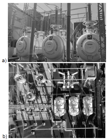
Research on the superconducting current limiter project started in 2015 and was carried out in three main stages: the engineering phase was completed in 2016, the procurement phase was finished in 2016-2018, and the construction phase was carried out in 2018 and 2019 (Fig. 4). The first launch and experimental tests were performed at the end of 2019 [9].
The superconducting fault current limiter consists of three external single-phase apparatus with a reservoir (hereinafter referred to as “phases”, Fig. 4) and a cooling system, which is located in a separate building with the dimensions of 7x14x10m3. The area occupied by the three phases of the surge arrester is similar to the area occupied by three air chokes (Fig. 4 b). The main technical data of the limiter are presented in Table 2 [9], [10].
Each of the SFCL limiter phases consists of a cryostat, high-voltage busbars and a set of superconductors (Fig. 5). The superconductor assembly consists of a set of current-limiting modules connected to high-voltage shields (corona rings).
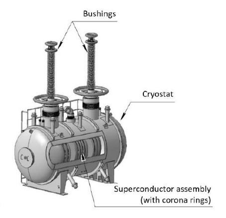
The corona rings help to evenly distribute the electric field inside the device, and the second-generation high-temperature superconducting tape serves as a switching resistor [9].
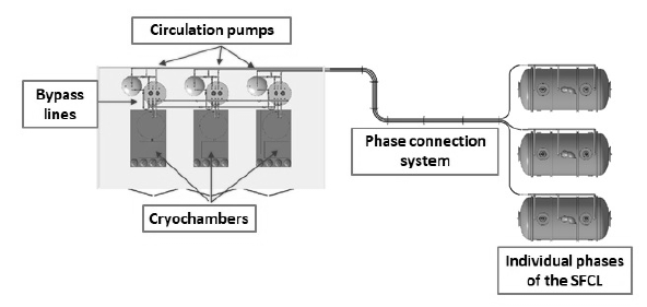
The SFCL cryostats were double-walled tanks with vacuum insulation. The walls were made of stainless steel to withstand the internal pressure. Each cryostat was leak tested with helium up to 15 bar. The special feature of these cryostats are two hatches removable from both sides, enabling maintenance, connection and disconnection of superconducting assemblies from the sleeves and other technical activities. The diameter of the holes was limited to 0.5 meters, which allowed access to the interior of the cryostat with a reasonable level of engineering difficulty. Each phase of the SFCL was equipped with its own cooling subsystem. The diagram of the limiter’s cooling system is shown in Figure 6 [9]. The cooling subsystem consists of a pressure builder, a Turbo-Brayton NeoKelvin cryochamber (rated cooling capacity 2kW at 70K, built by Taiyo Nippon Sanso), a circulation pump (Cryozone) and a pipe (Nexans) for transporting liquid nitrogen. Redundancy is ensured by bypassing the separate phases: even if one subsystem fails, the SFCL remains fully operational.
Superconducting fault current limiter R-SFCL 10 kV/1.8 kA
The project of a resistive superconducting fault current limiter 10 kV/1.8 kA was developed in Karlsruhe, Germany, on the basis of projects [11], [12]. The simulation tests of the R-SFCL application were based on the German medium voltage grid (Fig. 7) [13].
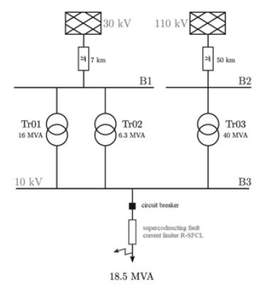
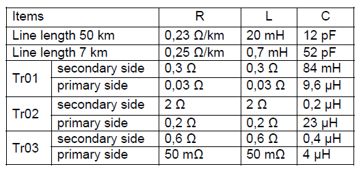
Table 3 presents the detailed parameters of the MV network fragment, which was tested with the use of the RSFCL superconducting current limiter [13].
Table 3. Parameters of medium voltage electrical network [15]
In the construction of the R-SFCL 10 kV/1.8 kA superconducting fault current limiter, the YBCO coil design was used in accordance with the ENSYSTROB design [11], [12]. The limiter consists of 25 coils connected in a series. Each coil consists of YBCO (Super Power SF12100) superconducting tapes and a stainless steel shunt resistor switched on in parallel. The superconducting coil is made of six tapes arranged in an anti-parallel arrangement. By designing the coils from six parallel tapes, the critical current IC R-SFCL reaches 1.8 kA (Ic for each tape is approximately 300 A).
Table 4. Performance of superconducting R-SFCL[13]

The SC winding of the limiter is cooled in liquid nitrogen at the temperature of 77 K. The main parameters of the R-SFCL subjected to simulation tests are presented in Table 4 [13].
Superconducting limiter for electrically powered aircraft
A very interesting design solution is the SFCL used in electrically powered aircraft [14]. The power of the system consists of three main units, including the aircraft’s electric propulsion system (EPAS), the main DC bus, and other receivers. The electric system consists of turbines, HTS generators, HTS cables and a superconducting fault current limiter [14], [15].
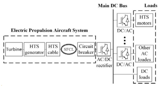
Together with the circuit break, the SFCL protects the system power against possible high fault current to maintain a high standard of safety in electric aircraft [14], [16].
All the bifilar coil designs to date have been dominated by the BCP design, where the inner and outer windings are connected in parallel. The result is a high current loss and a greater heat load for the cryogenic cooling system. In order to reduce losses and improve the ability to limit fault currents, a helical bifilar coil has been proposed, in which the inner and outer windings are connected in a series so that they conduct the same currents (reduction of the voltage difference between the turns near the terminals compared to the BCP type), and it will also guarantee an equal current distribution in the windings [17].

Summary
The progress in this area compared to previous years is increasing and promising. Currently, work on limiters is carried out in many institutes and research centres. Due to its technical parameters, simple structure and efficiency of limiting the fault current, the main direction of development of the superconducting fault current limiter is the resistive type. Resistive SFCLs are used in electric aircraft due to advantages such as: compactness, lightness and high reliability [1], [16]. Resistive SFCLs are configured as bifilar type to obtain non-inductive or low-inductance structures. This is very beneficial for power systems by avoiding poor voltage regulation and degraded power quality.
LITERATURE
[1] Kozieł J., Analiza wpływu impedancji uzwojenia wtórnego na parametry nadprzewodnikowych ograniczników prądu typu transformatorowego, Przegląd Elektrotechniczny, 2016, vol.92, no. 12, p.77-80, DOI: 10.15199/48.2016.12.20.
[2] Kozieł J., The influence of magnetic coupling factor k on value of impedance limiting fault current, Przegląd Elektrotechniczny, 2009, vol.85, no 5, p.200-203.
[3] Komarzyniec G. et al, Analysis of the current distribution in layers of a second generation superconducting tapes, Przegląd Elektrotechniczny, 2019, vol.95, no.1, p.65-68. DOI: 10.15199/48.2019.01.17.
[4] Kozak J, et al, Experimental Results of a 15 kV, 140A Superconducting Fault Current Limiter, IEEE Transactions on Applied Superconductivity, vol: 27, Issue: 4, 2017, Article Number: 5600504, DOI: 10.1109/TASC.2017.2651120.
[5] Gnat D., Aktualny stan badań nadprzewodnikowych ograniczników
prądu zwarcia, Praca magisterska, Politechnika Lubelska, 2021.
[6] Janowski J. et al. Superconducting Winding for Inductive Type SFCL Made of HTS Tape With Increased Resistivity, IEEE Transactions on Applied Superconductivity, Volume: 19, Issue: 3, 2009, Page(s): 1884 – 1887, DOI: 10.1109/TASC.2009.2018068.
[7] Dao V.Q., et al, Design and Performance Analysis of a Saturated Iron-Core Superconducting Fault Current Limiter for DC Power Systems, Energies, 2020, 13, 6090; DOI:10.3390/en13226090.
[8] Dao V.Q.; et al, Experimental Study on the Current Limiting Characteristics of a Saturated Iron-Core Superconducting Fault Current Limiter in DC Power Systems”, IEEE Transactions on Applied Supercond., vol. 31, No. 5, AUGUST 2021.
[9] Moyzykh M. et al, First Russian 220 kV superconducting fault current limiter (SFCL) for application in city grid, SuperOx, Nauchny t. 20, no.2, 117246, Moskwa, 2021.
[10] Moyzykh M. et al, Superconducting Fault Current Limiter for Moscow 220 kV City Grid, EUCAS, 2017
[11] Elschner S. et al, ENSYSTROB—Resistive fault current limiter based on coated conductors for medium voltage application, IEEE Trans. Appl. Supercond., t. 21, no. 3, p. 1209–1212, 2011.
[12] Elschner S. et al, ENSYSTROB—Design, manufacturing and test of a 3- phase resistive fault current limiter based on coated conductors for medium voltage application, Phys. C Supercond., t. 1, p. 1–7, 2012.
[13] de Sousa W.T.B., et al, Deployment of a Resistive Superconducting Fault Current Limiter for Improvement of Voltage Quality and Transient Recovery Voltage, IEEE Trans. Appl. Supercond., t. 31, no. 1,2021.
[14] Song W., et al, A Novel Helical Superconducting Fault Current Limiter for Electric Propulsion Aircraft , IEEE Trans. Transport. Electrify., t. 7, no. 1, 2021.
[15] Alafnan H., et al, Analysing faults and SFCL response in electric aircraft, Proc. 14th Eur. Conf. Appl. Supercond. (EUCAS), p.1–11, 2020.
[16] Morandi A., State of the art of superconducting fault current limiters and their application to the electric power system, Phys. C, Supercond., t. 484, p. 242–247, 2013.
[17] W. Song et al, Experimental and numerical transport AC losses in a four-strand Roebel cable bifilar stack, Supercond. Sci. Technol., t. 31, no. 11, 2018.
[18] Komarzyniec G. et al, The calculation of the inrush current peak value of superconducting transformers, 2015 Selected Problems of Electrical Engineering and Electronics, WZEE 201527 January 2016 Article number 7394042Selected Problems of Electrical Engineering and Electronics, WZEE 2015, Kielce, 17 September 2015 – 19 September 2015,
[19] Michałowska J. et al, Monitoring of the Specific Absorption Rate in Terms of Electromagnetic Hazards, Journal of Ecological Engineering, vol. 21, issue. 1, 2020 , https://doi.org/10.12911/22998993/112878,
[20] Michałowska J. et al, Monitoring the Risk of the Electric Component Imposed on a Pilot During Light Aircraft Operations in a High – Frequency Electromagnetic Field, Sensors, vol.10. no. 24, 2019, DOI: 10.3390/s19245537,
[21] Michałowska J.et al, Prediction of the parameters of magnetic field of CNC machine tools, Przegląd Elektrotechniczny.- 2019, vol. 95, no 1, p. 134-136, doi:10.15199/48.2019.01.34.
Authors: dr inż. Joanna Kozieł, Department of Electrical Engineering and Electrotechnologies, Faculty of Electrical Engineering and Computer Science, Nadbystrzycka 38A, 20-618 Lublin, e-mail: j.koziel@pollub.pl,mgr inż. Damian Gnat, Department of Electrical Engineering and Electrotechnologies, Faculty of Electrical Engineering and Computer Science, Nadbystrzycka 38A, 20-618 Lublin, e-mail: damian.gnat@pollub.edu.pl, dr hab. inż. Michał Majka, LUT Professor, Department of Electrical Engineering and Electrotechnologies, Faculty of Electrical Engineering and Computer Science, Nadbystrzycka 38A, 20-618 Lublin, e-mail: m.majka@pollub.pl mgr inż. Yerbol Turgynebekov, M. Kh. Dulaty Taraz State University, Kazakhstan, e-mail: bosik90@mail.ru
Source & Publisher Item Identifier: PRZEGLĄD ELEKTROTECHNICZNY, ISSN 0033-2097, R. 98 NR 2/2022. doi:10.15199/48.2022.02.36
