Published by Hana’ A. Rabab’ah 1, Yaser N. Anagreh2, Al-Ahliyya Amman University (1), Yarmouk University (2) ORCID: 1. 0000-0002-1581-7721; 2. 0000-0002-3826-9262
Abstract. This paper presents an integrated stand-alone wind / Photovoltaic (PV) system enhanced with storage system and the required controllers. The proposed scheme concerned with maximum electrical power extracting from the two renewable energy resources to maintain the DC bus with a fixed voltage, under different levels of wind speed and solar irradiation irrespective of the battery state of charge (SOC). To approach full utilization of the system components, proper power management strategy is implemented. The validity of the proposed scheme is confirmed through extensive simulation results under different operating conditions.
Streszczenie. W artykule przedstawiono zintegrowany, autonomiczny system wiatrowy / fotowoltaiczny (PV) wzbogacony o system magazynowania i wymagane sterowniki. Proponowany schemat dotyczył maksymalnej mocy elektrycznej wydobywanej z dwóch ´zródeł energii odnawialnej w celu utrzymania stałego napi˛ecia na szynie DC, przy ró˙znych poziomach pr˛edko´sci wiatru i napromieniowania słonecznego, niezale˙znie od stanu naładowania akumulatora (SOC). Aby zbli˙zy´c si˛e do pełnego wykorzystania elementów systemu, wdra˙zana jest wła´sciwa strategia zarz ˛adzania energi ˛a. Trafno´s´c proponowanego schematu jest potwierdzona wynikami szeroko zakrojonych symulacji w ró˙znych warunkach eksploatacyjnych. (Samodzielny system hybrydowy do pozyskiwania maksymalnej mocy i stałego napi˛ecia przy wahaniach obci ˛a˙zenia).)
Keywords: Battery Storage System, Integrated System, Maximum Power Point Tracker, Solar Energy, Wind Energy
Słowa kluczowe: system hybrydowy, ´sledzenie maksymalnej mocy, zasobnik energii
Introduction
Currently, there is an increasing interest in implementing renewable energy resources for electric power generation, especially in remote areas [1-6]. This is because the conventional energy resources, like gas and oil, will deplete, increase pollution to the environment and their price is affected by different factors [4, 5, 7-9]. Renewable energy (RE) resources, on the other hand, are abundantly freely available, environmentally friendly and they offer an efficient solution for both global warming and fluctuation in conventional fuel cost [4, 7, 9-12]. In addition, it is expected that the capital cost of installing RE systems will decrease due to the fast advances in the technologies concern with renewable energy and the growing demand for RE components, such as wind turbines and photovoltaic arrays [12-14]. Stand-alone RE systems could be installed using a single RE source, like wind only scheme [7], or combining two (or more) resources such as hybrid wind/solar system [1, 8]. Single source based RE system is subjected to discontinuous output power depending on the availability of this resource, like wind gusts or solar insolation [3, 15].
Integrated RE system equipped with a suitable backup storage system, like storage battery bank, will lead to more efficient, robust, and reliable system [2-5, 7-9, 12]. The backup storage system feeds the load demand when RE resources fail to generate the needed electric power. Wind turbines’ drive train determines the turbine classification; direct drive (DD); operating without a gear box or gear drive (GD) which is equipped with a gearbox [14]. Squirrel cage or double fed induction generators operated using GD type but the permanent magnet synchronous generators (PMSGs) are drived with DD type [14, 16, 17, 18]. PMSGs have been utilized in various stand-alone renewable energy conversion schemes due to their features over other generator types including reduced losses, lower maintenance requirement, higher reliability, higher efficiency, and low moment of inertia [2, 16, 18-21]. Photovoltaic (PV) technology is based on the conversion of solar energy into DC electric power using solar cells [8]. An array with the desired voltage and current can be obtained by connecting solar cells in series and parallel combinations [22]. A solar array provides electric power without noise or mechanical moving parts [22].
The generated output power of the photovoltaic arrays can be directly fed to DC loads, supplying AC loads via inverters, or stored in batteries to be used later [9, 22]. An integrated stand-alone renewable energy system comprising wind driven PMSG and PV generator, equipped with storage batteries and dump load, is proposed in the presents research work. The main goals of the proposed configuration are the extraction of maximum power from the renewable energy resources, providing reliable DC voltage source and fixed voltage fixed frequency AC source, and attaining full system utilization, under different environmental and loading conditions. Maximum power tracking from the PV array is achieved by implementing the PO algorithm. Extracting maximum power from the WT is accomplished by adjusting the boost chopper switching using two PI controllers. The system reliability in supplying the load demand and maintaining the output voltage fixed, under the variations in both wind speed and solar irradiation, is attained by combining the system with storage batteries and dump load, equipped with their needed controllers. To approach full utilization for the system components, appropriate power management system is implemented.
SYSTEM MODELING AND CONTROL
System Configuration
The schematic diagram of the proposed scheme is shown in Fig. 1. The two main power sources are the wind driven PMSG and PV generator. Two converters are utilized in the WECS and PV system at the DC link to feed the DC motor driving a water pump and to extract the maximum power from the two renewable energy resources. The battery bank is connected through the DC link, which is used to enhance the system reliability in feeding the load demand. Also, the DC link may supply the two three phase AC loads, through the three-phase inverter, when the generated power exceeds the load demand of the pump. The DC link may supply the two three phase AC loads, through the three-phase inverter, when the generated power exceeds the load demand of the pump. The Simulink model of the proposed system is shown in Fig. 2. The designed power management strategy organizing the system operation properly towards full utilization of the system components. The system operation can be categorized into four modes depending on the battery bank SOC and the RE resources availability regarding the wind speed and solar irradiation. WT only, PV generator only, WT and PV generator, and battery only mode.
Controllers Design
The proposed system objectives are achieved by adjusting the operation of the system elements through seven controllers. Two PI controllers are used to extract maximum power from WT, PO based controller for MPPT of the PV array, PI and hysteresis controllers for charging / discharging the battery bank, ON/OFF controller to maintain constant voltage at the DC link (dump load control), and PI-controller to adjust the speed of the DC motor. The following subsections explain the operation of the implemented controllers.
Maximum Power Point tracker of WT
The configuration of the MPPT controller used to track maximum power from the utilized variable speed WT at each wind speed is presented in Fig. 2. The implementation of this tracker can be summarized in the following steps: – Find the reference speed from the measured wind speed (Vw) using the following equation:
The measured speed (ωr) is subtracted from the reference speed (ω∗) to find the error signal, which is fed to the PI speed controller. – The output control signal of the PI speed controller represents the reference load current of the PI current controller. This signal is compared with the actual load current to obtain the error signal fed to the PI current controller. The output of the current controller represents the switching command for the boost DC chopper.
Maximum Power Point Tracker of PV Array
Perturb and Observe (P&O) method, which is commonly used to extract maximum power from the PV array due to its simplicity, is implemented to extract the maximum power from the implemented PV array for each solar irradiation level. In P&O approach the electric current or the terminal voltage of the PV array is perturbed at regular intervals which is illustrated in the flow chart shown in Fig. 3. The output from the P&O algorithm represents the command to adjust the DC chopper duty cycle resulting in extracting maximum output power from the PV array.
Battery Bank Charging / Discharging Control
Charging and discharging process of the storage batteries are accomplished using a bidirectional buck-boost DC chopper, as presented in Fig. 4. The error between the actual DC voltage and the reference set value is supplied to the PI controller. The output control signal of the PI-controller represents the reference signal of the current feeding the battery. This signal is then compared with the actual electric current to provide the hysteresis controller with the error signal. The control signal from the hysteresis controller represents the switching command (duty cycle) for switch S1 or/and switch S2 of the DC chopper, depending on the SOC of the battery.
DC Dump Load Control
The DC dump load is represented by a resistor which is controlled via a power electronic switch as shown in Fig. 5. When the total generated power from the wind driven PMSG and the PV generator is greater than the load demand and at the same time the SOC of the storage batteries approaches 80%, the power electronic switch is turned on and the excessive generated power is supplied to the dump load. When the SOC of the battery bank becomes greater than the upper limit (80%), the duty cycle of the switch is adjusted as a function of the over voltage in the DC bus.
DC-Motor Control
The closed loop PI speed control of the DC motor is shown in Fig. 6. The actual rotational speed is subtracted from the reference set speed to provide the error supplied to the controller. The output control signal (u) is compared with the saw-tooth repeating signal to generate the PWM signal. The later signal performs the switching sequence of the DC chopper switch to provide the motor with the required armature voltage to match the reference speed.
Power Management Strategy
The proposed power management strategy is presented in Fig. 7. It performs the appropriate function based on the generated power from two main power supplies (wind driven PMSG and PV generator), the state of charge of the battery bank and the required power to feed the main load (water pump coupled to DC motor). To achieve full utilization for the generated power, a two three-phase AC loads in addition to a DC dump load are considered in the proposed system. The total generated power from wind-driven PMSG and PV generator is compared with the needed power from the main load (5 hp DC motor driving water pump).
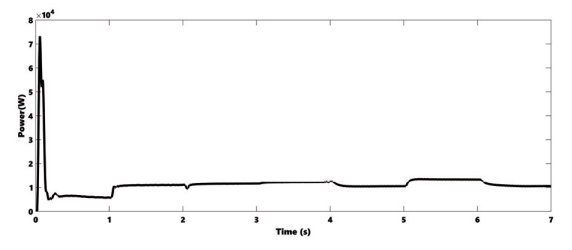
If the extracted power is higher than the needed power, the excess amount of power is used to charge the storage batteries. Once the SOC of the batteries attains 80%, load 1 is supplied. If the remaining excessive power, after feeding load 1, is high enough Load 2 will be supplied. If the wind speed and solar insolation are not enough to generate the power needed by the main load, the battery bank takes over to cover the load demand, if its SOC is greater than 80%, otherwise the motor is disconnected from the system. Results and Discussion The Simulink simulation model of the investigated system, including all system components, is shown in Fig. 8. The model includes variable speed wind turbine and surface mounted PMSG with their MPPT controllers, battery bank and dump load with the controllers, power conditioners (three phase diode rectifier, DC choppers, three-phase voltage source inverter), separately excited DC motor as a dynamic DC load, with its speed controller, two three-phase static AC secondary loads and power management scheme. Fig. 9 and Fig. 10 show wind speed and solar irradiation profiles, respectively. These profiles are used to assess the proposed system performance under the changes in the atmospheric conditions. The generated electrical output power from wind driven PMSG, PV-array and the storage battery bank are shown in Fig. 11, Fig. 12 and Fig. 13, respectively. It can be noticed that the variations in the atmospheric conditions; wind speed and solar irradiation, play an important role in the generated output power from the two renewable energy sources. In other words, the curve for the results of the generated output power from each source follows the same manner of its considered profile. The maximum and minimum generated power from the two main power sources, during the considered profiles, are 10.39 kW and 5.607 kW, respectively. This is sufficient to meet the main load demand (DC motor driving water pump) for the complete considered period. Due to insufficient wind speed or / and solar irradiation during certain intervals the total generated power from the two sources could not meet the load demand of AC load 2 of 5 kW, or even AC load 1 of 2.kW. Enhancing the generated power with the battery bank output power, which is shown in Fig. 13, enables the system to cover the load demand of AC load 1 for nearly the whole considered period. The remaining power is not enough to supply the additional AC load 2 of 5 kW as can be noticed in Fig. 14.
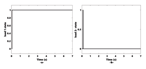

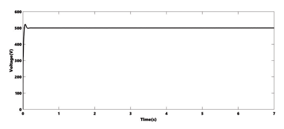
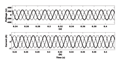


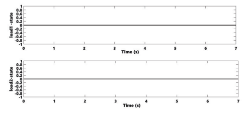
Fig. 15 shows the dump load ON/OFF states. The ON state presents the case when the DC link voltage is greater than the reference value and the battery bank SOC is above 80%. The dump load remains OFF as along as the DC link voltage below the reference value or the battery bank SOC is below 80%. As a result of controlling the states of the dump load, the DC bus voltage remains constant at the prescribed value. The response of the DC bus voltage during the considered profiles is shown in Fig. 16. It can be noticed that the DC link voltage has a fast response with very small percentage overshoot before is settled down to its final value of 500 V. Moreover, the voltage response has approximately zero steady-state error. The waveforms for the three-phase voltages and three-phase currents obtained from the inverter are shown in Fig. 17. It can be seen that the inverter provides fixed voltage and frequency supply. The speed response of the DC motor for different values of reference set speeds is shown in Fig. 18. It can be noticed that high performance speed control is achieved. The speed characteristic has a fast-dynamic response with nearly no overshoot and approximately zero steady state error. Fig. 19 presents the obtained output DC voltage for the profiles of Fig. 9 and Fig. 10, when storage batteries and dump load are excluded from the proposed configuration. It can be seen that the DC voltage is not fixed, but it is varying in response to the environmental condition (changes in wind speed and/or solar irradiation). The reduction in the DC voltage below certain limit will badly affecting the DC motor speed control. Moreover, the exclusion of the storage batteries will extend the shortage period in feeding the load demand. This can be observed in Fig. 20 where the two AC loads are OFF for the complete considered period. These results validate the importance of enhancing the system with a storage battery bank and dump load incorporated with their needed controllers.
Conclusion
The performance of the proposed off-grid integrated wind driven PMSG / PV system, enhanced with storage batteries and dump load, have been assessed. The obtained results demonstrate the capability of the system in extracting maximum power to provide fixed DC voltage source as well as fixed voltage fixed frequency three phase AC supply, under different environmental and loading conditions. Moreover, the results confirm the ability of the implemented power management strategy in approaching efficient utilization of the system components, under varying atmospheric conditions.
REFERENCES
[1] CA. Chatterjeea, A. Brenta, R. Rayudua, and P. Vermaa, ” Microgrids for rural schools: an energy-education accord to curb societal challenges for sustainable rural developments”, Int. Journal of Renewable Energy Development, vol. 18, no 3, pp. 231-241, October 2019.
[2] Priya, Ramalingam Adikesavan, Devaraj Dhanasekaran, and Parasurama Chandrasekaran Kishoreraja. “Performance analysis of PMSG based wind energy conversion system using two stage matrix converter.” Przeglad Elektrotechniczny 2 (2019).
[3] Y. Abu Eldahab, N. Saad, and A. Zekry, ” Enhancing the energy utilization of hybrid renewable energy systems”, Int. Journal of Renewable Energy Research, vol.10, no 4, December 2020.
[4] S. Omran, and R. Broadwater, “Grid integration of a renewable energy system: modeling and analysis”, Int. Journal of Renewable Energy Research, vol.10, no 3, September 2020.
[5] Y. Nassar, M. Abdunnabi, M. Sbeta, A. Hafez, K. Amer, A. Ahmed, and B. Belgasim, ” Dynamic analysis and sizing optimization of a pumped hydroelectric storage integrated hybrid PV/wind system: A case study”, Energy Conversion and Management, vol. 229, December 2020.
[6] M. Azaroual, M. Ouassaid, and M. Maaroufi, “An optimal energy management of grid-connected residential photovoltaicwind-battery system under step-rate and time-of-use tariffs”’, Int. Journal of Renewable Energy Research, vol. 10, no 4, pp.1829-1843, December 2020.
[7] B. Sun, ” A multi-objective optimization model for fast electric vehicle charging stations with wind, PV power and energy storage”, Journal of Cleaner Production, Accepted for publication in December 2020.
[8] R. Putri, M. Rifa’i, I. Syamsiana, and F. Ronilaya, ” Control of PMSG stand-alone wind turbine system based on multiobjective PSO”, Int. Journal of Renewable Energy Research, vol.10, no 2, pp. 998-1004, June 2020.
[9] A. Masih, and H. Verma, “Optimization and reliability evaluation of hybrid solar-wind energy systems for remote areas”, Int. Journal of Renewable Energy Research, vol.10, no 4, pp. 1696-1707, December 2020.
[10] Y. Anagreh, A. Alnassan, and A. Radaideh, ” High performance mppt approach for off-line pv system equipped with storage batteries and electrolyzer”, Int. Journal of Renewable Energy Development, vol. 10, no 3, pp. 507-515, February 2021.
[11] S. Marih, L. Ghomri, and B. Bekkouche, “Evaluation of the Wind Potential and Optimal Design of a Wind Farm in the Arzew Industrial Zone in Western Algeria”, Int. Journal of Renewable Energy Development, vol. 9, no 2, pp. 177-187, May 2020.
[12] P. Nema, R. Nema, and S. Rangnekar, “A current and future state of art development of hybrid energy system using wind and PV-solar: A review”, Renewable and Sustainable Energy Review, Vol. 13, no 8, pp. 2096–2103, October 2009.
[13] B. Bhandari, S. Poudel, K. Lee, S. Ahn, “Mathematical modeling of hybrid renewable energy system: A review on small hydrosolar-wind power generation”. Int Journal of precision Enginering and Manufactoring- Green Technology. vol. 1, pp. 157–173, April 2014.
[14] A. Tawfiq, M. Abed El-Raouf, A. El- Gawad, and M. Farahat, “Analysis the impact of renewable energy based-wind farms installed with electrical power generation system on reliability assessment”, Int. Journal of Renewable Energy Research”, vol.10, no 4, pp. 1595-1607, December 2020.
[15] S. Bisoyi, R. Jarial, and R Gupta, “Modeling and Analysis of Variable Speed Wind Turbine equipped with PMSG”. Int. Journal of Current Engineering Technology, vol. 2, pp. 421–426, February 2014.
[16] A. Chouaib, H. Messaoud, and M. Salim, “Sizing and optimization for hybrid central in south Algeria based on three different generators”, Int. Journal of Renewable Energy Development, vol. 6, no 3, pp. 263-272, September 2017.
[17] F. Blaabjerg, and K. Ma, “Wind energy systems”. Proceedings of IEEE, vol. 105, no 11, pp. 2116–2131, May 2017.
[18] M. Khan, J. Wang, L. Xiong, and M. Ma, ” Fractional Order Sliding Mode Control of PMSG-Wind Turbine Exploiting Clean Energy Resource”, Int. Journal of Renewable Energy Development, vol. 8, no 1, pp. 81-89, January 2019.
[19] O. Anaya-Lara, N. Jenkins, J. Ekanayake, P. Cartwright, and M. Hughes, Wind Energy Generation: Modelling and Control, John Wiley and Sons, 2009.
[20] ELmorshedy M., S. M. Allam S., and Rashad E., “Load voltage control and maximum power extraction of a stand-alone wind-driven PMSG including unbalanced operating conditions”, Eighteenth International Middle East Power Systems Conference (MEPCON), 27-29 Dec. 2016
[21] K. Hasan, Control of power electronic interfaces for photovoltaic power systems, M.Sc. Thesis, Univresity of Tasmania, Australia, August 2009.
[22] M. Husain, and A. Tariq, “Modeling and study of a standalone PMSG wind generation system using Matlab/Simulink”, Universal Journal of Electrical and Electronic Engineering, vol. 2, no 7, pp. 270–277, 2014.
Authors: M. Sc. Hana’ A. Rabab’ah, Al-Ahliyya Amman Univeristy, Faculty of Engineering, Amman, Jordan, email: han.rababah@ammanu.edu.jo, Prof. Yaser N. Anagreh, Yarmouk University,Hijjawi Faculty of Engineering Technology, Irbid, Jordan, email: y.anagreh@yu.edu.jo
Source & Publisher Item Identifier: PRZEGL ˛ AD ELEKTROTECHNICZNY, ISSN 0033-2097, R. 98 NR 7/2022. doi:10.15199/48.2022.07.13
