Published by Stanisław GAWRON, Jakub BERNATT, Artur POLAK,
Sieć Badawcza Łukasiewicz – Instytut Napędów i Maszyn Elektrycznych KOMEL
Abstract. Three variants of starting synchronous motors are presented. In simplest solution, cage winding is placed in rotor, asynchronous start-up is obtained. This method generates large surge currents adversely affecting power grid and motor (impact forces/impact torque are generated). The second solution is to place three-phase ring winding in rotor – asynchronous start-up is obtained, same as in slip-ring induction motors. Start-up is smooth. Asynchronous phase of start-up is terminated by synchronization. The third method is frequency start-up. Drive system must contain additional frequency inverter. Start-up is smooth. This is recommended primarily for set of several motors installed in the plant.
Streszczenie. W artykule przedstawiono trzy wariantowe sposoby rozruchu silników synchronicznych. Najprostszym rozwiązaniem jest umieszczenie w wirniku uzwojenia klatkowego i rozruch asynchroniczny. Ten sposób rozruchu wymusza duże prądy udarowe niekorzystnie oddziałujące na sieć elektroenergetyczną i na silnik, gdyż generują siły udarowe i moment udarowy. Drugim rozwiązaniem jest umieszczenie w wirniku uzwojenia trójfazowego pierścieniowego i rozruch asynchroniczny, identycznie jak w silnikach indukcyjnych pierścieniowych. Rozruch przebiega łagodnie. Rozruch asynchroniczny kończy się synchronizacją. Trzecim sposobem rozruch jest rozruch częstotliwościowy. Układ napędowy musi być wyposażony w dodatkowy falownik z regulacją częstotliwości. Rozruch jest łagodny. Taki sposób rozruchu poleca się przede wszystkim dla grupy kilku silników zainstalowanych w firmie. (Rozruch silników synchronicznych wzbudzanych magnesami trwałymi).
Słowa kluczowe: silniki synchroniczne, rozruch asynchroniczny, rozruch częstotliwościowy.
Keywords: synchronous motors, asynchronous starting, frequency starting.
Introduction
High power machinery operating in mines, steel plants, chemical works and other industrial plants is often driven by synchronous motors with electromagnetic excitation. When synchronous motors are compared to induction motors, we find that their power efficiency is higher and they operate at capacitative power factor cosφ, so that reactive power in the plant may be compensated. Lately, some attempts have been made to apply synchronous motors with permanent magnet excitation to these drives. Such motors do not require exciters and their efficiency is higher. However, the problem of start-up must be resolved.

Asynchronous start-up utilizing cage winding
The asynchronous start-up of synchronous motors is most commonly used. Apart from excitation winding present in rotor of synchronous motor, another start-up winding is mounted; usually this is a cage winding. When stator winding is connected to the power network, current flowing in cage winding interacts with stator current and asynchronous torque emerges; this causes the rotor to rotate and accelerate up to near-synchronous speed. At this point, excitation current is switched on and rotor self-synchronizes. The end windings of rotor in synchronous motor with cage winding are shown in Fig.1 (the wrappings have been taken out).
Oscillogram of start-up current for motor rated at 1250 kW, 6 kV is shown in Fig.2. This is motor with electromagnetic excitation and cage start-up winding, the so-called SAS motor. This particular motor is installed in copper ore ball mill.
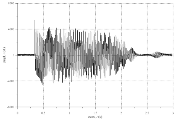
The recorded value of surge current is Iu = 5500 A or 40I_N; this is a very high value. The start-up lasted for 2.5 seconds, so we are able to classify this as a short start-up. The surge current generates axial impact forces and impact torque. The impact forces lead to high stresses and radial vibrations, which negatively affect the stator’s winding insulation, magnetic circuit, motor’s structural elements, bearings and foundations. The impact torque affects the coupling and gear box, and this may lead to teeth shearing.
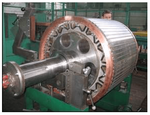
The cage start-up winding has also been used in synchronous motor with permanent magnet excitation [7]. In this design, rotor contains permanent magnets as well as cage winding. The permanent magnets are placed in slots within rotor yoke, and cage winding consists of copper bars placed in slots along rotor’s outer circumference. These bars are short-circuited with end rings. The start-up takes place at full excitation provided by the PM-generated magnetic flux. Rotor of prototype motor dedicated to a fan drive in one of the coal mines is shown in Fig.3.
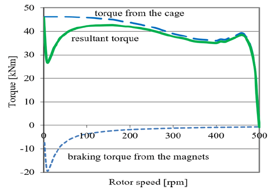
Calculated curves for starting torque of this motor are shown in Fig.4. The rated torque is TN = 21 kNm. On the basis of presented curves, it may be concluded that total start-up torque over entire speed range is greater than rated torque.
Synchronous motor excited by permanent magnets, type SMH-1732T, rated at: 630 kW, 6 kV, 63 A, 187.5 rpm, 32.1 kN·m drives the copper ore ball mill. Attempt was made to record speed and vibration waveforms of this motor during start-up, but it failed. Current and vibration surges exceeded measurement ranges of the transducers and the measurement devices froze. The maintenance staff did not allow a retry. We may assume that current waveform during start-up would be similar as in the case of SMH-1732S motor (Fig. 2), but surge current will be higher.
Asynchronous start-up utilizing ring winding
Machinery with high moment of inertia is characterized by long start-up times. The starting time becomes longer, if start-up takes place with loaded motor. This sort of start-up may occur in service and the drive motor should be able to withstand such conditions. The synchronous machines proposed for such drives are equipped with start-up ring windings. These are synchronized asynchronous motors (popularly termed SAS). Rotor winding in such motor is usually three-phase and it fulfils the role of start-up winding as well as excitation winding. The start-up is rheostatic and identical to that of typical induction slip-ring machine. When near-synchronous speed is reached by the motor, excitation current is switched on and self-synchronization takes place. Identical start-up winding has been applied to motors with permanent magnet excitation, these are so-called SASPM motors [2]. There are several possible design variants. Rotor with permanent magnets nested inside rotor yoke is shown in Fig.5. Winding is placed in slots along the rotor circumference and its ends are led out to the slip rings.
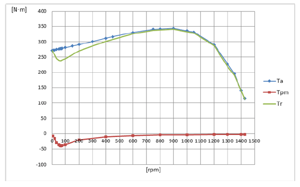
Torque-speed curves of model motor SASPM rated at 1.5 kW, 400 V, 1500 rpm (slip rings shorted) are shown in Fig. 6. They relate to: Ta – asynchronous torque generated by rotor winding, Tpm – torque due to permanent magnets, Tr – total torque.
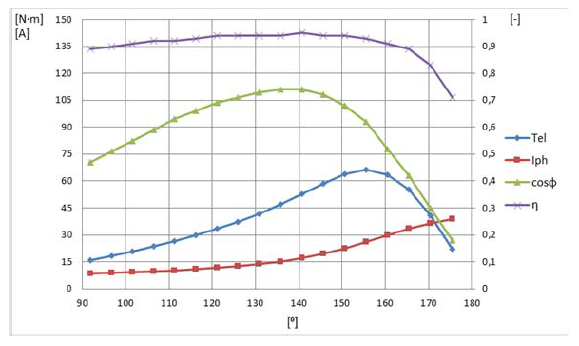
Synchronous characteristics of model motor are shown in Fig.7, these are torque Tel, current Iph, power factor cosφ and efficiency η curves. The start-up proceeds in identical manner as in slip-ring induction motor. During the start-up, stator/rotor currents are much lower than in cage winding. The start-up is smoother. At near-synchronous speed the slip rings are opened, excitation current is turned on, synchronizing torque pulls the rotor and it accelerates up to synchronous speed – self synchronization takes place. Oscillograms of stator and rotor current for a SAS motor driving a mill in a cement plant are presented in Fig.8.

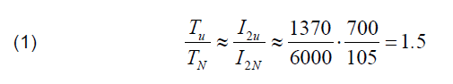
The envelope of rotor current is proportional to motor’s asynchronous torque. When motor supply is switched on, surge current appears and it reaches 4.3 IN. When the rheostat is switched and its resistance changes, the current (RMS-value) does not exceed 1.2IN. Rotor’s surge current is equal to 700 A. The impact torque is calculated on the basis of rotor current waveform in the following way:
The start-up is smooth.
Frequency start-up
If several electric motors are present in large industrial works, then it is a good idea to use a smooth (soft) frequency start-up. The frequency start-up of synchronous machines has been known for a long time and used for start-ups of synchronous compensators [4] and high-power synchronous motors. It is also perfectly suited to the startup of synchronous motors excited with permanent magnets. A single AC/DC/AC inverter may be used for a group of motors together with synchronizer and switches (see Fig.9). The synchronizer may be built into inverter. A single inverter operating with several motors means that investment costs are less, since high power motors are rated at 6 kV or 10 kV and inverter’s rated voltage must be the same.
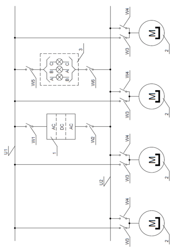
Synchronous motors M (2) excited with permanent magnets are connected to the power system (U1) via switches W3 and to inverter AC/DC/AC (1) via switches W4. All elements of the circuit are three-phase ones. One AC/DC/AC inverter (1) serves four motors M (2). The frequency control range of this inverter should extend from minimum c. 3 Hz to 50 Hz, with rotational emf to frequency ratio. AC/DC/AC inverter (1) executes the start-up of each motor M (2) separately. Number of motors may vary. AC/DC/AC inverter (1) is supplied from the same power network (U1) as the motors.
The start-up of each motor M (2) progresses in a following way:
• AC/DC/AC inverter (1) is connected to the power network (U1) by switch W1,
• inverter (1) is connected to bus U2 by switch W2; minimum frequency value is set at the inverter (1),
• selected motor M (2) is connected to bus U2 by switch W4; inverter’s frequency is increased up to subsynchronous
value, e.g. 49.5 Hz,
• synchronizer (3) is connected to network U1 and bus U2 via switches W5 and W6,
• motor is synchronized with power network U1 by adjusting frequency of inverter (1),
• when frequency is adjusted and the phase sequence is correct, switch W3 is tripped and switch W4 is switched off; this constitutes end of start-up.
The system inverter-synchronizer is ready for subsequent start-up (another motor M). If this start-up is not required, then inverter 1 should be disconnected from the network U1 via switch W1 and from bus U2 via switch W2. Synchronizer 3 should also be disconnected from network U1 and bus U2 (breakers W5 and W6 are switched off).
If the circuit is to be constructed economically, then inverter and synchronizer should be connected directly to bus U2, breakers W2 and W6 may be absent.
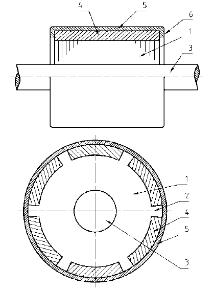
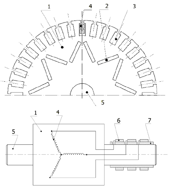
The presented start-up system guarantees a smooth, surgeless start-up of PM synchronous motors. This start-up method offers one more advantage, permanent magnets 4 may be glued into the channels outside the rotor yoke 1. The terminal laminations are uncut and therefore they provide additional protection to the permanent magnets (against axial shift). The magnetic flux in the air-gap is maximum, since permanent magnets are located at the rotor yoke surface and they are not shunted by the yoke. The flux determines the maximum synchronous torque of the motor. The motor equipped with such rotor exhibits higher torque overload capacity than motor with permanent magnets affixed inside yoke slots. Rotor should be also fitted with winding attenuating hunting due to variable component of load torque. This role may be fulfilled by a copper sleeve 5 located on the permanent magnets (see Fig.10). Ends of the sleeve are turned back, constituting flange 6. This protects the sleeve against axial displacement.
In the magnetic circuit, the copper sleeve 5 is placed in the air-gap. This rotor design is recommended for medium and high power motors. In these machines the air-gap is usually greater than 2 mm and placing a 1 mm thick sleeve in this slot does not pose technological problems. The relative magnetic permeability of copper is the same as of air. Sleeve 5 does not decrease excitation’s magnetic flux, while it ensures attenuation of the rotor hunting.
Conclusion
High power synchronous motor with permanent magnet excitation must be designed for start-up conditions. The simplest solution is to place a cage winding in the rotor. When cage winding is used, start-up is achieved by connecting motor to the supply network; when synchronous speed is attained, motor self-synchronizes. This type of start-up is accompanied by high surge current which has negative impact on the power network as well as on the motor itself, since it generates impact forces and torque.
The second design is based upon placing a three-phase ring winding in the rotor. The start-up is executed by connecting a rheostat to the rotor winding circuit. The startup is asynchronous and its progress is identical as in slipring induction motors. When near-synchronous speed is attained, motor self-synchronizes. The start-up is smooth, but the rotor construction is much more expensive.
The third start-up method is frequency start-up. The drive system is equipped with additional inverter operating on frequency control principle. During start-up, motor is accelerated up to synchronous speed and synchronized with network voltage. After synchronization the inverter is disconnected. During starting process, synchronous torque is used and start-up is smooth. In this design, additional cost is incurred (inverter). This start-up procedure is mostly recommended for a group of several motors installed on the company premises.
REFERENCES
[1] J. Bernatt J., T.Glinka, “Asynchronous Slip-Ring Motor Synchronized with Permanent Magnet”, Archives of Electrical Engineering. ISSN 1427-4221. Nr 1/2017, pp. 199-206.
[2] J. Bernatt., S. Gawron, T.Glinka, E.Pacholski, K. Staszewski,: Wirnik silnika elektrycznego z magnesami trwałymi. Patent PL 226639 ogłoszono: 31.08.2017. Instytut Napędów i Maszyn
Elektrycznych KOMEL.
[3] W. Paszek, Stany nieustalone maszyn elektrycznych prądu przemiennego. WNT, ISBN 83-204-0707-9, 1986.
[4] R.Rossa, Silnik reluktancyjny z dodatkowym wzbudzeniem magnesami trwałymi. Praca doktorska. Biblioteka Politechniki Śląskiej. Listopad 2006 r.
[5] T.Zawilak, Utilizing the deep bar effect in direct on start of permanent magnet machines, Przegląd Elektrotechniczny. ISSN 0033-2007. Nr 2/2013. s. 177 – 179.
[6] T. Zawilak, J. Zawilak, Silnik synchroniczny wzbudzany magnesami trwałymi w napędzie młyna kulowego, Maszyny Elektryczne – Zeszyty Problemowe, ISSN 0239-3646. Nr 3/2016 r. s. 169 – 173.
[7] T. Zawilak, J. Zawilak, Wirnik silnika elektrycznego z magnesami trwałymi. Patent PL nr 218489, ogłoszono. 31.12.2014. Politechnika Wrocławska.
[8] T. Zawilak, J. Zawilak: “Energooszczędne silniki synchroniczne dużej mocy wzbudzane magnesami trwałymi”, Przegląd Elektrotechniczny, ISSN 0033-2097, R. 91 NR 10/2015, str.117-120.
Authors: dr inż. Stanisław Gawron, e-mail: stanislaw.gawron@komel.lukasiewicz.gov.pl; dr hab. inż. Jakub Bernatt, prof. Ł-KOMEL e-mail: jakub.bernatt@komel.lukasiewicz.gov.pl; dr inż. Artur Polak, e-mail: artur.polak@komel.lukasiewicz.gov.pl; Sieć Badawcza Łukasiewicz – Instytut Napędów i Maszyn Elektrycznych KOMEL, Al. Roździeńskiego 188, 40-203 Katowice.
Source & Publisher Item Identifier: PRZEGLĄD ELEKTROTECHNICZNY, ISSN 0033-2097, R. 97 NR 5/2021. doi:10.15199/48.2021.05.01
