Published by Electrical Installation Wiki, Chapter M. Power harmonics management – Solutions to mitigate harmonics
There are three different types of solutions to attenuate harmonics:
• Modifications in the installation
• Special devices in the supply system
• Filtering
Basic solutions to mitigate harmonics
To limit the propagation of harmonics in the distribution network, different solutions are available and should be taken into account particularly when designing a new installation.
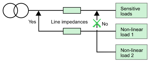
Position the non-linear loads upstream in the system
Overall harmonic disturbances increase as the short-circuit power decreases.
All economic considerations aside, it is preferable to connect the non-linear loads as far upstream as possible (see Fig. M24).

Group the non-linear loads
When preparing the single-line diagram, the non-linear devices should be separated from the others (see Fig. M25). The two groups of devices should be supplied by different sets of busbars.
Create separate sources
In attempting to limit harmonics, an additional improvement can be obtained by creating a source via a separate transformer as indicated in the Figure M26.
The disadvantage is the increase in the cost of the installation.
Transformers with special connections
Different transformer connections can eliminate certain harmonic orders, as indicated in the examples below:
• A Dyd connection suppresses 5th and 7th harmonics (see Fig. M27)
• A Dy connection suppresses the 3rd harmonic
• A DZ 5 connection suppresses the 5th harmonic
Install reactors
When variable-speed drives are supplied, it is possible to smooth the current by installing line reactors. By increasing the impedance of the supply circuit, the harmonic current is limited.
Installation of harmonic suppression reactors on capacitor banks increases the impedance of the reactor/capacitor combination for high-order harmonics.
This avoids resonance and protects the capacitors.
Select the suitable system earthing arrangement
TNC system
In the TNC system, a single conductor (PEN) provides protection in the event of an earth fault and the flow of unbalance currents.
Under steady-state conditions, the harmonic currents flow in the PEN. Because of the PEN impedance, this results in slight differences in potential (a few volts) between devices that can cause electronic equipment to malfunction.
The TNC system must therefore be reserved for the supply of power circuits at the head of the installation and must not be used to supply sensitive loads.
TNS system
This system is recommended if harmonics are present.
The neutral conductor and the protection conductor PE are completely separate and the potential throughout the distribution network is therefore more uniform.
Harmonic filtering
In cases where the preventive action presented above is insufficient, it is necessary to equip the installation with filtering systems.
There are three types of filters:
• Passive
• Active
• Hybrid
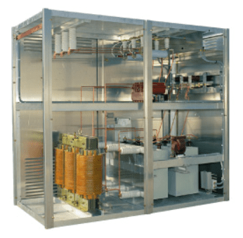
Passive filters
Typical applications
• Industrial installations with a set of non-linear loads representing more than 500kVA (variable-speed drives, UPSs, rectifiers, etc.)
• Installations requiring power-factor correction
• Installations where voltage distortion must be reduced to avoid disturbing sensitive loads
• Installations where current distortion must be reduced to avoid overloads
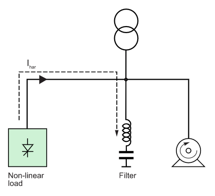
Operating principle
An LC circuit, tuned to each harmonic order to be filtered, is installed in parallel with the non-linear load (see Fig. M28). This bypass circuit absorbs the harmonics, thus avoiding their flow in the distribution network.
Generally speaking, the passive filter is tuned to a harmonic order close to the order to be eliminated. Several parallel-connected branches of filters can be used if a significant reduction in the distortion of a number of harmonic orders is required.
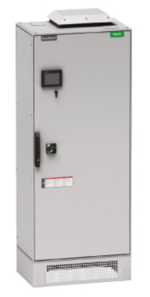
Active filters (active harmonic conditioner)
Typical applications
• Commercial installations with a set of non-linear loads representing less than 500kVA (variable-speed drives, UPSs, office equipment, etc.)
• Installations where current distortion must be reduced to avoid overloads.
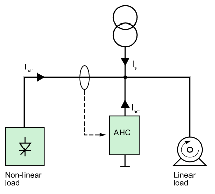
Operating principle
These systems, comprising power electronics and installed in series or parallel with the non-linear load, compensate the harmonic current or voltage drawn by the load.
Figure M29 shows a parallel-connected active harmonic conditioner (AHC) compensating the harmonic current (Ihar = -Iact).
The AHC injects in opposite phase the harmonics drawn by the non-linear load, such that the line current Is remains sinusoidal.
Hybrid filters
Typical applications
Industrial installations with a set of non-linear loads representing more than 500kVA (variable-speed drives, UPSs, rectifiers, etc.)
• Installations requiring power-factor correction
• Installations where voltage distortion must be reduced to avoid disturbing sensitive loads
• Installations where current distortion must be reduced to avoid overloads
• Installations where strict limits on harmonic emissions must be met
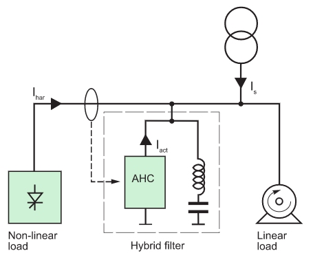
Operating principle
Passive and active filters are combined in a single system to constitute a hybrid filter (see Fig. M30). This new filtering solution offers the advantages of both types of filters and covers a wide range of power and performance levels.
Selection criteria
Passive filter
It offers both power-factor correction and high current-filtering capacity. Passive filters also reduce the harmonic voltages in installations where the supply voltage is disturbed. If the level of reactive power supplied is high, it is advised to turn off the passive filter at times when the percent load is low.
Preliminary studies for a filter must take into account the possible presence of a power factor correction capacitor bank which may have to be eliminated.
Active harmonic conditioners
They filter harmonics over a wide range of frequencies and can adapt to any type of load. On the other hand, power ratings are limited.
Hybrid filters
They combine the performance of both active and passive filters.
The method to optimize harmonics mitigation
The best solution, in both technical and financial terms, is based on the results of an in-depth study.
Harmonic audit of MV and LV networks
By calling on an expert, you are guaranteed that the proposed solution will produce effective results (e.g. a guaranteed maximum THDu).
A harmonic audit is carried out by an engineer specialised in the disturbances affecting electrical distribution networks and equipped with powerful analysis and simulation equipment and software.
The steps in an audit are the following:
• Measurement of disturbances affecting current and phase-to-phase and phase-to-neutral voltages at the supply source, the disturbed outgoing circuits and the non-linear loads
• Computer modelling of the phenomena to obtain a precise explanation of the causes and determine the best solutions
• A complete audit report presenting:
– The current levels of disturbances
– The maximum permissible levels of disturbances (refer to IEC 61000, IEEE 519, etc.)
• A proposal containing solutions with guaranteed levels of performance
• Finally, implementation of the selected solution, using the necessary means and resources.
The entire audit process should be certified ISO 9002.
Source URL: https://www.electrical-installation.org/enwiki/Solutions_to_mitigate_harmonics
