Published by Electrical Installation Wiki, Chapter M. Power harmonics management – Essential indicators of harmonic distortion and measurement principles
A number of indicators are used to quantify and evaluate the harmonic distortion in current and voltage waveforms, namely:
• Power factor
• Crest factor
• Harmonic spectrum
• R.m.s. value
These indicators are indispensable in determining any necessary corrective action.
Harmonic distortion indicators – Power factor
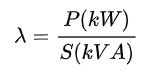
The power factor λ is the ratio of the active power P (kW) to the apparent power S (kVA).
See Chapter Power Factor Correction.
The Power Factor must not be mixed-up with the Displacement Power Factor (cos φ), relative to fundamental signals only.
As the apparent power is calculated from the r.m.s. values, the Power Factor integrates voltage and current distortion.
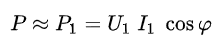
When the voltage is sinusoidal or virtually sinusoidal (THDu ~ 0), it may be said that the active power is only a function of the fundamental current. Then:
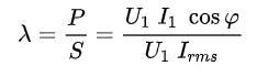
Consequently:
As:
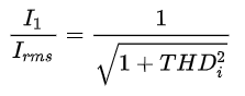
(see Definition of harmonics),
hence:
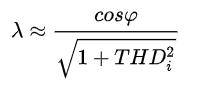
Figure M6 shows a graph of λ/cosφ as a function of THDi, for THDu ~ 0.
Harmonic distortion indicators – Crest factor
The crest factor is the ratio between the value of the peak current or voltage(IM or UM) and its r.m.s. value.
• For a sinusoidal signal, the crest factor is therefore equal to √2.
• For a non-sinusoidal signal, the crest factor can be either greater than or less than √2.
The crest factor for the current drawn by non-linear loads is commonly much higher than √2. It is generally between 1.5 and 2 and can even reach 5 in critical cases.
A high crest factor signals high current peaks which, when detected by protection devices, can cause nuisance tripping
Examples:
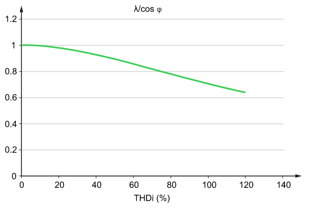
Figure M7 represents the current absorbed by a compact fluorescent lamp.
Ir.m.s. = 0.16A
IM = 0.6A
THDi = 145%
Crest factor = 3.75
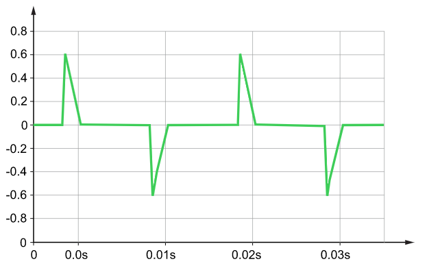
Figure M8 represents the voltage supplying non-linear loads through a high impedance line, with a typical “flat top” distorted waveform.
Vr.m.s. = 500V
VM = 670V
THDu = 6.2%
Crest factor = 1.34
Harmonic spectrum
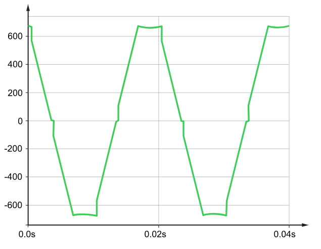
The harmonic spectrum is the representation of the amplitude of each harmonic order with respect to its frequency.
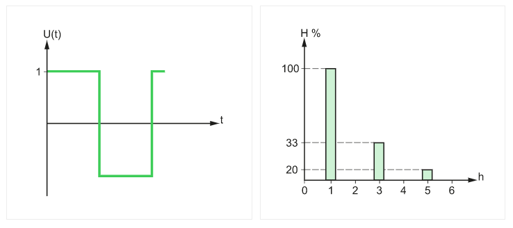
Figure M9 shows an example of harmonic spectrum for a rectangular signal.
Each type of device causing harmonics draws a particular form of current, with a particular harmonic content. This characteristic can be displayed by using the harmonic spectrum.
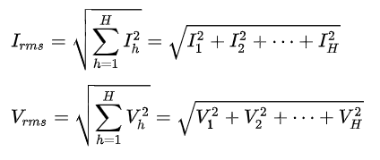
R.m.s. values
The r.m.s. value of voltage and current can be calculated as a function of the r.m.s. value of the various harmonic components:
Usefulness of the various indicators of Harmonic distortion
THDu is an indicator of the distortion of the voltage wave.
Below are given indicative values of THDu and the corresponding consequences in an installation:
• ≤ 5%: normal situation, no risk of malfunctions,
• 5 to 8%: significant harmonic distortion, some malfunctions are possible,
• ≥ 8%: major harmonic distortion, malfunctions are probable. In-depth analysis and the installation of mitigation devices are required.
THDi is an indicator of the distortion of the current wave.
The current distortion can be different in the different parts of an installation. The origin of possible disturbances can be detected by measuring the THDi of different circuits.
Below are given indicative values of THDi and the corresponding phenomena for a whole installation:
• ≤ 10%: normal situation, no risk of malfunctions,
• 10 to 50%: significant harmonic distortion with a risk of temperature rise and the resulting need to oversize cables and sources,
• ≥ 50%: major harmonic distortion, malfunctions are probable. In-depth analysis and the installation of mitigation devices are required.
Power factor λ is used to determine the rating for the different devices of the installation.
Crest factor is used to characterise the aptitude of a generator (or UPS) to supply high instantaneous currents. For example, computer equipment draws highly distorted current for which the crest factor can reach 3 to 5.
Harmonic spectrum provides a different representation of electrical signals and can be used to evaluate their distortion.
Author: This Electrical Installation Wiki is a collaborative platform, brought to you by Schneider Electric: our experts are continuously improving its content, collaboration is also open to all.
The Electrical Installation Guide (wiki) has been written for electrical professionals who must design safe and energy efficient electrical installation, in compliance with international standards such as the IEC 60364.
