Published by Adam SMOLARCZYK1, Tadeusz DASZCZYŃSKI1, Sławomir FISZER2
Warsaw University of Technology, Electrical Power Engineering Institute (1), Elektroteam Sp. z o.o. (2)
Abstract. The article describes an innovative low voltage switchgear for use in the pulp and paper industry. The switchgear is an innovative structure designed to supply single-phase systems with significant currents above 1 kA. The switchgear uses a special transformer with windings connected in the V system. The scope of the tests of the secondary and primary circuits of the switchgear and their selected results are presented.
Streszczenie. W artykule opisano innowacyjną rozdzielnicę niskiego napięcia do zastosowania w przemyśle celulozowo-papierniczym. Rozdzielnica stanowi innowacyjną konstrukcje przeznaczoną do zasilania jednofazowych układów o prądach przekraczających 1 kA. W rozdzielnicy zastosowano transformator specjalny z uzwojeniami połączonymi w układzie V. Przedstawiono zakres zaproponowanych, w ramach projektu badawczego, badań obwodów wtórnych i pierwotnych rozdzielnicy oraz wybrane ich wyniki. (Badania rozdzielnicy nn do zasilania układów rozbijania włókien celulozy).
Keywords: LV switchgear, switchgear testing, pulp and paper industry.
Słowa kluczowe: rozdzielnica niskiego napięcia, testowanie rozdzielnic, przemysł celulozowo-papierniczy.
Introduction
The wood and paper industry includes the sawmill industry, the board and plywood industry, the furniture industry, and the pulp and paper industry. The pulp and paper industry in Poland is developing well. It is a branch of industry that arouses great interest among foreign investors. The production of cellulose and paper requires large amounts of water. Therefore, the largest plants are located on large rivers. The largest paper producers include plants in Świecie, Kwidzyn, Ostrołęka, Kostrzyn, Kielce, Szczecin, Krapkowice and Klucze [1].
The functional requirements for the tested low voltage switchgear (LV) have been defined for the purposes of supplying equipment and production lines of the domestic pulp and paper production plants. These plants use techniques for the production of pulp and paper, as well as derived products such as, for example, cellulose sponges. Manufacturing processes require significant amounts of thermal energy obtained through electricity. The control of the production process requires the supply of electricity with specific voltage and current parameters in the required power cycles.
The pulp and paper industry is characterized by a high degree of production diversification, so the technologies of power devices (including switchgears) should be flexible in design (adaptation to the needs of a given production line at the design stage) and operation (adapting the supply conditions to the requirements of a given manufacturing process).
In Poland, there are many pulp and paper plants subject to the IPPC Directive (Integrated Pollution Prevention and Control) [2]. Pursuant to this directive, the volume of pollutant emissions in manufacturing processes is subject to BAT standards (Best Available Techniques) [3], which define emission limit values and are used in larger plants in the European Union. Power equipment should enable manufacturing processes to be adapted to the directive. The functional requirements of the LV switchgear used to supply the cellulose fiber breaking systems are:
– low supply voltage below 1 kV,
– significant current of more than 1 kA,
– possibility of cyclical supply of loads with various current levels,
– modularity of power devices enabling configurability and adaptation of power systems to the specifics of a given production line
The innovativeness of the switchgear (compared to other LV switchgears) is based on the use of a special transformer in each cell supplying cellulose cooking systems, the windings of which are connected to a V system.
Testing of LV switchgears
According to [4] the features of low-voltage switchgear should ensure compatibility with the rated data of the circuits to which it is connected, and the installation conditions should be declared by the switchgear manufacturer. All devices, electrical apparatus and low-voltage switchgear circuits should be so arranged as to facilitate operation and maintenance, and at the same time to maintain an appropriate degree of safety.
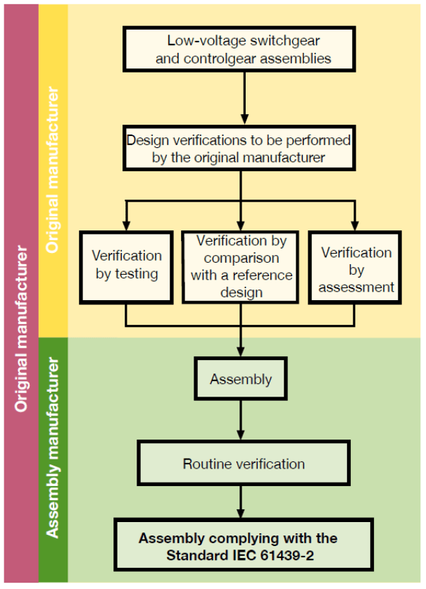
It should be noted that, in accordance with the [4] standard, there are three methods of verification (Fig. 1): tests, comparisons, calculations – they are considered equivalent. It does not mean, however, that each of the points in the standard can be verified in any way by one of the three methods. It has been precisely defined how (using an appropriate method) individual requirements can be verified. In practice, this means that e.g. the short-circuit withstand requirements cannot be verified by calculation, but have to be verified by a test. It should be remembered that testing the switchgear under short-circuit conditions is a destructive test.
According to [4] the tests of impulse withstand voltage, temperature rise limits, short-circuit withstand test, EMC and mechanical operation should be carried out. There is no more reliable method of verification than hardware laboratory tests, therefore, although the standard allows for some points to be verified by e.g. calculations, taking into account the safety of operation and powered devices, as well as the correctness of the switchgear parameters verification, the Ordering Party accepted the test at all points using the most appropriate reliable method, that is, through research.
There are some methods that can be used for verification of construction of a switchgear like FEM methods [6]. The process can be divided into two-stage simulation approach which includes electromagnetic and CFD analysis coupled together. The output of electromagnetic simulation is heat loss generated as the results of Joule heating and induction of eddy current on sheet metal parts of the enclosure. Heat loss in an input for further CFD simulation. CFD simulation is used to calculate radiation and natural convection.
Switchgear construction
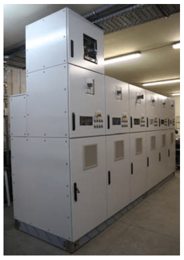
The LV switchgear was tested in the Laboratory of Electrical Apparatus and Switching Process in Electrical Power Engineering Institute at Warsaw University of Technology. The switchgear was manufactured by Electroteam Sp. z o.o. and the tests were carried out from May till end of June 2020.
Based on the analysis of the technical documentation of the LV switchgear, it was found that it consists of a power supply section and six outflow sections supplying cooking cells. (Fig. 2) [7].
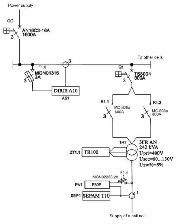
The switchgear delivered for testing consists of the main power supply section equipped with the LS Susol AN-16C3- 16A main switch (QG) and one outlet section supplying the cooking cell [7]. The cooking cell feeding section consists of:
– LS Susol TS 800N section compact switch (Q1),
– two power contactors (K1.1, K1.2) Metasol MC-800a by LS for switching the primary terminals of the TR1 transformer of the cooking cell,
– a transformer (TR1) type 3FR AN with a electrical power of 242 kVA by BREVE,
– Socomec three-phase network parameters analyzer (AS1) DIRIS A10 installed on the upper voltage side of TR1 transformer,
– digital overcurrent relay (SEP1) Sepam 10 B 43E by Schneider Electric for low voltage side circuits of transformer TR1,
– a single-phase converter of network parameters (PV1) P30P by Lumel installed on the lower voltage side of the TR1 transformer,
– digital transformer TR1 (ZT1.1) temperature control relay of the TR-100 type by Novatek-Electro.
In addition to the above-mentioned elements, the switchgear provided for testing includes elements such as fuse switch disconnectors, installation switches, lamps, switches, current transformers, a fan, a 24 V DC power supply, auxiliary relays.
Fig. 3 shows a single-line diagram of the LV switchgear delivered for testing. It shows all the main above-mentioned primary elements as well as protection and measurement systems used in the switchgear.
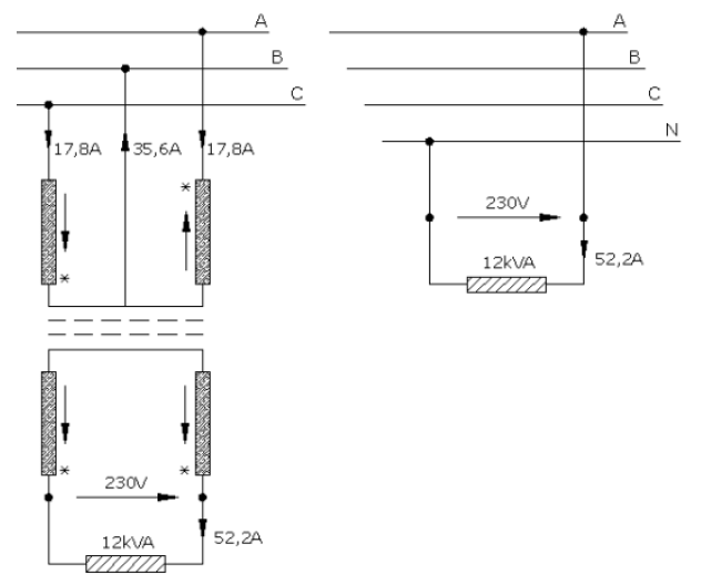
An important element of each outlet section of the switchgear is a transformer, the windings of which are connected in a V system (the use of this type of transformer proves the switchgear innovation). A special transformer of this type is used as intermediary devices to reduce the unfavourable load asymmetry in a three-phase supply network in the case of supplying a single-phase load with high power from this network. The traditional supply of high-power single-phase loads with phase-to-phase voltage from a three-phase network causes a strong asymmetry in the electrical network by loading only two phases. The essence of the issue is explained in Fig. 4.
The switchgear uses a special transformer type 3FR AN with an electrical power of 242 kVA by BREVE (Fig. 5)
The transformer is supplied from a three-phase LV network with phase-to-phase voltage of 400 V. The voltage (and current) is changed on its secondary side by applying phase-to-phase voltages to the appropriate taps (installed in phases L1, L3) of the transformer’s primary side. The range of obtainable voltages and currents on the secondary side of the transformer are shown in Table 1
Table 1. 3FR AN transformer available secondary voltage and current
| V | 60 | 70 | 80 | 90 | 100 | 110 | 120 | 130 |
| kA | 2,5 | 2,5 | 2,5 | 2,5 | 2,3 | 2,2 | 2,0 | 1,85 |
It should be noted that the transformer loads the network in phases L1 and L3 with a current of approx. 349 A, and in phase L2 with a current of approx. 698 A.
The scope of the research carried out
After reviewing the technical documentation of the switchgear and comparing its features with devices available on the market (task 1 of the research project [7]), the following switchgear tests were carried out (or planned):
– current path tests and checking the current conduction system (task 2),
– performance of voltage resistance tests (task 3),
– performance of functional short-circuit tests (task 4),
– testing of protection automation systems (task 5).
Tests of current circuits and checking the switchgear current conduction system
The laboratory setup for testing the current load capacity was located in the Laboratory of Electrical Apparatus and Switching Processes of the Institute of Electrical Power Engineering, Warsaw University of Technology. The test circuit consisted of: inductive regulator, short-circuit transformers, switchgear under test. The system was powered by mains voltage, the short-circuit transformers were connected in a triangle on the primary side. The short-circuit transformers were star-connected on the secondary side, and the voltage on this side of the short-circuit transformers was 110 V AC. The tested LV switchgear was connected to short-circuit transformers with 2x YKY 1×150 mm2 cables per phase. The currents on individual phases were measured with a CMP-2000 clamp meter.
Impulse withstand voltage test
The following tests were performed:
– test with withstand voltage at the mains frequency of main, auxiliary and control circuits connected to the main circuit,
– withstand voltage test at the mains frequency of auxiliary and control circuits not connected to the main circuit,
– test with impulse withstand voltage of the main, auxiliary and control circuits connected to the main circuit,
– test with impulse withstand voltage of auxiliary and control circuits not connected to the main circuit.
All tests were made in accordance with [4]. Voltage levels depending on the voltage of the main, control and auxiliary circuits.
Short-circuit withstand strength test
According to [4], for switchgears where the contractual short-circuit current exceeds 10 kA, the rated short-circuit currents must be tested and verified. When verifying, the following should be used:
– if the distribution system under verification covers several variants, the least favorable one should be selected,
– if the tested kits are the least favorable variants from a wider group of products in the distribution system, then the test results can be used to evaluate similar variants without performing tests.
Tests of protection automatics and measurement systems used in the switchgear
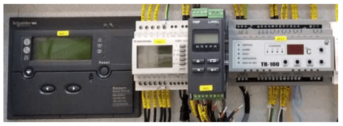
The protection automatics and measurement systems of the tested switchgear (secondary circuits) include (Fig. 6):
– temperature control relay (ZT1.1) TR-100,
– overcurrent relay (SEP1) Sepam 10 B 43E,
– network parameters analyzer (AS1) DIRIS A10,
– network parameters transducer (PV1) P30P.
Fig. 3 shows a diagram of the connection of individual elements of the switchgear secondary circuits. Elements such as: TR-100 relay, DIRIS A10 analyzer and P30P transducer exchange data (temperature, currents, voltages, powers) with the supervisory system using the Modbus RTU protocol and telecommunications link in the RS-485 standard.
As part of task five of the research project [8] tests were carried out:
– analysis of possible disturbances in the operation of the tested system,
– analysis of the control and signaling system,
– analysis of the correct selection of protection functions and their interaction within the protected device,
– analysis of the correctness of the selection of settings for protection functions used in the tested system,
– laboratory tests of the functions of the SEPAM 10 B device,
– laboratory tests of the TR-100 device functions,
– tests of correctness of data exchange between switchgear devices and the supervisory system.
Most of the tests (forcing currents and voltages) were performed using a CMC 256plus microprocessor tester [10] and a precise resistance decade MDR-93-6b (simulation of Pt100, KTY83 temperature sensors).
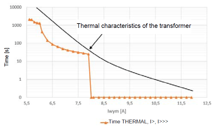
On the basis of the conducted tests, it was determined whether the tested device behaves as expected, e.g. whether it provides (or not) a signal to its binary outputs after simulating a specific type of disturbance. For example, Fig. 7 shows the resultant characteristic t(I) of the current functions activated and set in the Sepam 10 B relay. It is also shown how the characteristics of the overcurrent functions set in the relay should follow the theoretical thermal (heating) characteristics of the TR1 transformer, so that it is not damaged.
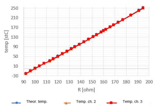
Fig. 8 shows the R(temp) charts of the theoretical and real characteristics of the TR-100 relay (channels 2 and 3). As you can be seen, the actual graphs of temperature measurement by the TR-100 relay are in line with the theoretical graph of temperature changes suitable for the Pt100 sensor.
Conclusions
The switchgear provided for testing is innovative due to the specificity of its application (pulp and paper industry) and the placement of a special transformer with windings connected in the V system in its cell. The tests performed as part of the research project were divided into several tasks.
Comprehensive tests, according to [4], to which the switchgear was given concerned: (a) tests of current paths and checking the current conduction system, (b) voltage withstand tests, (c) functional short-circuit tests, (d) tests of protection automatics and measurement systems.
The switchgear tests were positive. In most cases, the tested switchgear systems (primary and secondary circuits) behaved as expected. In the case of protection systems, the behavior of the Sepam 10 B and TR-100 relays was, in some cases, not as expected.
REFERENCES
[1] Bulletin of Association of Polish Papermakers, 2016-2018, No 11, ISSN 1436-2517
[2] Council Directive 96/61/EC of 24 September 1996 concerning integrated pollution prevention and control (IPPC)
[3] M. Michniewi cz i inni, Najlepsze Dostępne Techniki (BAT). Wytyczne dla branży celulozowo-papierniczej, Raport sfinansowany ze środków Narodowego Funduszu Ochrony Środowiska i Gospodarki Wodnej na zamówienie Ministra Środowiska, Ministerstwo Środowiska, Warsaw, August 2005
[4] PN-EN 61439-1:2011 Low-voltage switchgear and controlgear assemblies – Part 1: General rules
[5] Technical Application Papers No.11 Guidelines to the construction of a low-voltage assembly complying with the Standards IEC 61439 Part 1 and Part 2, ABB SACE A division of ABB S.p.A. L.V. Breakers, 06/2016
[6] T . Kądziołka, M. Kryś , A. Wier tek, Analysis of power loss and temperature distribution in low voltage switchgear – coupled analysis EM + CFD in ANSYS software, Przegląd Elektrotechniczny, 94 (2018), No 1
[7] T . Daszc z yński, M. Szewczyk, A. Smolarczyk, S. Stoczko , Zadanie 1. – Wykonanie przeglądu dokumentacji technicznej i porównanie cech z urządzeniami istniejącymi, Raport z pracy badawczej, Nr projektu POIR.02.03.02-10-0023/19, Warsaw, March 2020
[8] A. Smolarczyk, K. Kurek, R. Kowal i k, M. Januszews k i , M. Szewczyk, T. Daszczyński , Zadanie 5 – Wykonanie testów układów automatyki zabezpieczeniowej, Raport z pracy badawczej, Nr projektu POIR.02.03.02-10-0023/19, Warsaw, June 2020
[9] M. Łukiewi cz, Transformator z uzwojeniami w konfiguracji Vv firmy Elhand, Elektrosystemy, September 2006
[10] OMICRON elec t ronic s, https://www.omicronenergy.com/en/ products/cmc-256plus/, on-line access: 2.06.2020
Authors: dr hab. inż. Adam Smolarczyk, Warsaw University of Technology, Electrical Power Engineering Institute, ul. Koszykowa 75, 00-662 Warsaw, Poland, E-mail: adam.smolarczyk @ien.pw.edu.pl, dr inż. Tadeusz Daszczyński, Warsaw University of Technology, Electrical Power Engineering Institute, ul. Koszykowa 75, 00-662 Warsaw, Poland, E-mail: tadeusz. daszczyński@ien.pw.edu.pl, Sławomir Fiszer, Elektroteam Sp. z o.o., ul. Brzozowa 8A, 97-400 Bełchatów, Poland, E-mail: s.fiszer@elektroteam.com.pl
Source & Publisher Item Identifier: PRZEGLĄD ELEKTROTECHNICZNY, ISSN 0033-2097, R. 96 NR 11/2020. doi:10.15199/48.2020.11.38
