Published by Liu Liqun, Liu Chunxia*, Taiyuan University of Science & Technology
Abstract. At present, an optimal maximum power tracking (MPPT) and grid-connected control methods for a PV power system are very important to improve the output efficiency. However, most of literatures only introduce the MPPT or PLL method, respectively. A novel MPPT method is proposed by improving the convention perturbation and observation (P&O) method in this paper, which can track the real peak of PV array at different irradiation and partial shading. To analyze the locked performance, the Single Synchronous Reference Frame Software Phase Locked Loop (SSRF-SPLL) is discussed at different grid faults such as single phase voltage drop, two phase voltage drop, and frequency discontinuity.
Streszczenie. W artykule przedstawiono algorytm MPPT oparty na zmodyfikowanej metodzie perturbacji i obserwacji, umożliwiający śledzenie punktu mocy maksymalnej zespołu paneli PV w warunkach niejednorodnego nasłonecznienia i częściowego zacienienia. W celu analizy działania systemu podłączonego do sieci elektroenergetycznej, zastosowano algorytm synchronizacji fazowej PLL o pojedynczej ramce. (Sterowanie zespołem paneli PV podłączonym do sieci elektroenergetycznej – algorytmy MPPT i SSRF-SPLL).
Keywords: PV array; Maximum Power Point Tracking; Partial shading; Phase Locked Loop.
Słowa kluczowe: tablica paneli PV, MPPT, częściowe zacienienie, PLL.
Introduction
With the increasing concern about global environmental protection, the need to produce pollution-free natural energy such as solar energy has received great interest as an alternative source of energy for the future since solar energy is clean, pollution-free and inexhaustible. In an effort to use the solar energy effectively, a great deal of research has been done on the grid-connected photovoltaic generation systems [1]. Grid interconnection of PV power system has the advantage of more effective utilization of generated power. However, the technical requirements from both the utility power system grid side and the PV system side need to be satisfied to ensure the safety. Normally, there are many problems need solve to satisfy of the PV installer and the reliability of the utility grid such as islanding detection, harmonic distortion requirements and electromagnetic interference, etc [2]. A Grid-Connected PV Power Systems (GCPPS) consists of the PV array, the inverter, the convert, test module, and protect module, and so on. Here the output direct current (DC) of PV power system is converted to the alternate current (AC) to generate power to utility. In order to extract the maximum power from the costly PV modules, the MPPT control method is necessary by controlling the duty cycle of the switch of the DC–DC inverter. Furthermore, the DC-AC converter is used to convert the DC current to sinusoidal current and inject into the grid, and to satisfy the need of grid utilization, the output voltage and frequency of AC from converter must be same to that of the grid, which is easy to realize. However, the instantaneous voltage, frequency, and phase is difficult to gain, certainly, the grid-connected between PV power system and the grid becomes a difficult task. A Phase-Locked Loop technology is necessary to satisfy the grid-connected need.
Many synchronization techniques have been presented over the recent years. In synchronous reference frame based Phase Locked Loop (PLL) based systems, the phase angle estimation is adaptively updated by a closed loop mechanism whose objective is to track the actual frequency and phase angle [3]. The three-phase grid-connected converter is widely used in renewable and electric power system applications. Traditionally, control of the three-phase grid-connected converter is based on the standard decoupled d–q vector control mechanism [4]. Moreover, there are many factors affect the grid-connected characteristic such as the change of the temperature, irradiation and partial shading. And the different MPPT and PLL methods affect the output efficiency of PV power system and the safety of the grid utilization. Many international application examples have been introduced in some literatures [5]. Nevertheless, most of them only introduce the PLL or MPPT control method. This article presents a design case of PV power system which considers the MPPT and grid-connected to improve the output performance and reduce the loss of PV system and satisfy the need of grid-connected. Firstly, the topology structure is described. A novel improved P&O MPPT method is introduced in the next section. Then, the SSRFSPLL is used in this GCPPS, and the output characteristic of SSRF-SPLL at different grid faults are described [6]. Finally, simulation results demonstrate the correctness of the proposed method.
Topology structure of the GCPPS
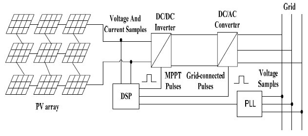
Fig.1 shows the topology structure of the GCPPS. Here, multiple series-parallel PV modules become a PV array, and the DC bus is connected with the DC-DC inverter, then the DC output is injected into the DC-AC converter. Finally, the AC output is injected into the grid. Certainly, test module and control module are necessary to insure the satisfy performance. For example, the output voltage and output current signals of PV array are sampled to calculate the optimal Pulse-Width Modulation (PWM) and track the maximum power point at the time. Furthermore, the three-phase output voltages of grid are sampled to gain the optimal grid-connected PWM using the PLL technology.
Proposed MPPT method
There is only one maximum power point (MPP) of PV array at uniform irradiation, and the MPPT method is very easy such as P&O, incremental conductance, fuzzy logic, etc. Current–voltage and power–voltage characteristics of large PV arrays under partially shaded conditions are characterized by multiple steps and peaks [7]. In these reasons, tracking the MPP is difficult under the partial shading or non-uniform conditions [8]. Rapidly changing shadow conditions increase the difficulty of MPPT [9]. In order to track the real MPP of PV array at partial shading, the conventional P&O method is improved in this section.

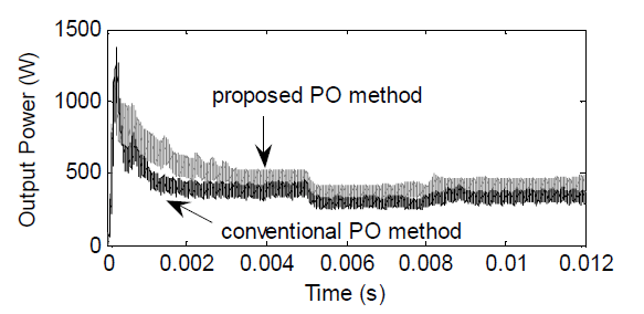
Fig.2 shows that there are three MPP at partial shading, and the B point is the real MPP (called the global peak (GP)) and the A and C points are called the local peaks (LP). Certainly, the conventional P&O method has been described in many literatures which can track the LP (A point) as can be seen from Fig.2. However, which can not track the GP (B point) under the partially shaded conditions. An easy improvement can improve the output performance of the conventional P&O method. When the conventional P&O method tracks the A point and the PWM reaches the stable value PWMA . A perturbation is added in the PWMA , and the perturbation range is ± 30% of PWMA and the perturbation step is 0.5% of PWMA . Fig.3 shows that the proposed method have better output efficiency and sensitivity and response speed of improved method as compare with the conventional P&O method.
Grid-connected output using the SSRF-SPLL
In grid-connected systems, accurate phase angle and frequency of utility voltage is essential since the voltage or current reference is synchronized with the phase of the utility voltage for various applications such as power factor correction, active/reactive power control [3]. The phase angle estimation of SSRF-SPLL is adaptively updated by a closed loop to track the actual frequency and phase angle, and the structure is very simple, which is widely accepted synchronization algorithm for grid connected systems.
The three phase voltages Va , Vb , Vc are expressed as equation (1).

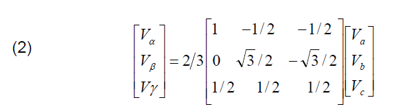
The three-dimensional coordinates are transformed into the stationary reference frame signals Vα and Vβ as can be expressed in (2). Where, Vγ = 0 because of Va , Vb , Vc are symmetrical.
The stationary reference frame signals are transformed to the rotating reference frame signals Vd and Vq .
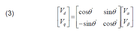
Where θ‘ = w’t , and w’ is the angular frequency of the rotating dq frame, and t is the time. θ is the actual phase and θ‘ is the accurate estimate. When θ‘ – θ = 0 , the PLL gets locked to the utility voltage. Vm is the magnitude of voltage. And a proportional-integral (PI) controller is used in Vq . The model diagram of SSRF-SPLL can be seen from Fig.4. PI controller is equivalent to a loop filter, and Kp and Ki are the parameters of PI, which are 10 and 802, respectively.

There are some questions affect the grid-connected performance of PV power system, such as the change of output voltage amplitude of PV array due to the change of solar irradiation, the single-phase voltage drop or the two phase voltage drop or voltage offset or the frequency discontinuity due to the grid failures. It is very important to consider different faults because of which affects the output efficiency and performance.
To clarify the correctness and effectiveness of SSRF-SPLL, the ideal situation, single-phase voltage drop, two phase voltage drop, and frequency discontinuity are considered in this section. As shown in Fig.5, the SSRF-SPLL can track the frequency and voltage of grid, which has high precision and rapid response speed. Fig.6 (a) shows the tracking performance of frequency locked at different grid faults, and two phase voltage drop has the largest frequency oscillation. Fig.6 (b) shows the voltage locked at voltage drop, and the tracking performance is worst at two phase voltage drop. In other words, the SSRF-SPLL is different to gain the correct frequency of grid when single-phase or two phase voltage drop. The performance of voltage locked at frequency discontinuity can be seen from Fig.7. The SSRF-SPLL technologies can rapid lock the Voltage and frequency as shown in Fig.7 (a). Here, Fig.7 (b) shows the partial enlarged drawing at frequency discontinuity, and the change span is from 50Hz to 40Hz.


The comparison of phase locked of different situations can be seen from Fig.8. The phase locked performance is excellent under ideal or frequency discontinuity conditions as compare with that of single-phase voltage drop or two phase voltage drop.
Conclusions
The total control methods of MPPT and PLL using GCPPS is described in this paper. First, the proposed MPPT method can track MPP at different irradiation or shading. Second, the output performances of SSRF-SPLL at different grid faults are described to pay attention to select the optimal PLL technology based on different grid faults.
Acknowledgments: this work was supported by the Program for the Industrialization of the High and New Technology of Shanxi province (NO: 2010016), Youth Science Foundation of Shanxi province (NO: 2011021014-2), Doctor Fund of Taiyuan University of Science & Technology (NO: 20122018).
REFERENCES
[1] L. Hassaine, E. Olias, J. Quintero, M. Haddadi. Digital power factor control and reactive power regulation for grid-connected photovoltaic inverter, Renewable Energy, 34(2009) No.1, 315-321.
[2] Mohamed A. Eltawil, Z. Zhao. Grid-connected photovoltaic power systems: Technical and potential problems—A review, Renewable and Sustainable Energy Reviews, 14(2010) No.1, 112-129.
[3] B. Indu Rani, C.K. Aravind, G. Saravana Ilango, C. Nagamani. A three phase PLL with a dynamic feed forward frequency estimator for synchronization of grid connected converters under wide frequency variations, International Journal of Electrical Power and Energy Systems, 41(2012) No.1, 63-70.
[4] S. Li, Timothy A. Haskew, Yang-Ki Hong, L. Xu. Direct-current vector control of three-phase grid-connected rectifier–inverter, Electric Power Systems Research, 81(2011) No.2, 357-366.
[5] J. H. So, Y. S. Jung, G.J. Yu, J. Y. Choi, J. H. Choi. Performance results and analysis of 3 kW grid-connected PV systems, Renewable Energy, 32(2007) No.11, 1858-1872.
[6] S. K. Chung. A phase tracking system for three phase utility interface inverters, IEEE Transactions on Power Electronics, 15(2000) No.3, 431-438.
[7] H. Patel, V. Agarwal. Maximum power point tracking scheme for PV systems operating under partially shaded conditions, IEEE Trans. Ind. Electronics, 55 (2008) No.4, 1689-1698.
[8] Karatepe, E. Syafaruddin, T. Hiyama. Artificial neural network-polar coordinated fuzzy controller based maximum power point tracking control under partially shaded conditions, IET Renewable Power Generation, 3(2009) No.2, 239-253.
[9] L. J. Gao, Roger A. Dougal, S. Y. Liu, Albena P. Iotova. Parallel-connected solar PV system to address partial and rapidly fluctuating shadow conditions, IEEE Trans. Ind. Electronics, 56 (2009) No.5, 1548-1556.
Authors: Assistant prof. L.Q. Liu, college of electronic and Information engineering, Taiyuan University of Science & Technology, Waliu road 66, Wanbolin district, Taiyuan, China, Email: llqd2004@163.com; Assistant prof. C.X. Liu, College of computer science & technology, Taiyuan University of Science & Technology, Waliu road 66, Wanbolin district, Taiyuan, China, Email: lcx456@163.com.
Source & Publisher Item Identifier: PRZEGLĄD ELEKTROTECHNICZNY, ISSN 0033-2097, R. 89 NR 3a/2013
