Published by Electrotek Concepts, Inc., PQSoft Case Study: Distribution Feeder Resonance and Harmonic Filter Evaluation, Document ID: PQS1006, Date: March 15, 2010.
Abstract: Utility power system harmonic problems can often be solved using a comprehensive approach including site surveys, harmonic measurements, and computer simulations.
This case study presents the results for a utility distribution feeder resonance and harmonic filter evaluation. The analysis was completed using the PSCAD program. The study evaluated the effects of distribution capacitor banks on the frequency response characteristic and the resulting harmonic distortion levels.
INTRODUCTION
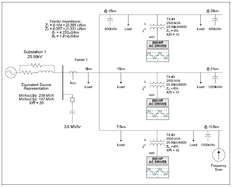
A utility distribution feeder resonance and harmonic filter evaluation was completed for the system shown in Figure 1. The case study was completed using the PSCAD program. The accuracy of the simulation model was verified using three-phase and single-line-to-ground fault currents and other steady-state quantities, such as capacitor bank rated current.
The circuit model for the case involved a 25.56kV utility substation and a single 25.56kV feeder with three 2,500 kVA step-down transformers supplying 500 hp ac drive loads.
SIMULATION RESULTS
The case study evaluated the effect of distribution feeder capacitor banks on the frequency response characteristics and the resulting voltage distortion levels. The mitigation alternative of passive harmonic filters was also evaluated. Figure 2 shows the simulated customer current waveform and spectrum for the 500 hp ac drives. The current has a fundamental frequency value of 497 amps, an rms value of 561 amps, a power factor of 80.3%, and a current THD value of 52.5%. The highest components were the 5th harmonic with a value of 48.2% and the 7th harmonic with a value of 17.5%.

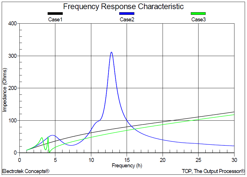
Figure 3 shows the results for the three frequency scan simulations. Case #1 was the base case with no utility capacitor banks included in the model. Case #2 was the case with all of the 25.56kV capacitor banks in service. Case #3 was the case with all of the 25.56kV capacitor banks reconfigured as 4.2nd harmonic filters. The scan was at the end of the distribution feeder. The parallel resonances for Case #2 were approximately 276 Hz (4.6th) and 768 Hz (12.8th).
Table 1 summarizes the results for the three simulations. The table includes the simulated voltage distortion (THD) at the end of the feeder near the 1,200 kVAr capacitor bank for the three different operating conditions. A single case exceeded the voltage limitation of 5% THD. Reconfiguring the capacitor banks as 4.2nd harmonic filters in Case 3 reduced the voltage distortion to below 5% THD.
Figure 4 shows the transformer primary current waveform for the customer drive current previously shown in Figure 2. The waveform shows the effect of the transformer connection and phase shift on the drive current characteristic.
Table 1 – Summary of the Simulation Results
| Case Number | 25.56kV Feeder VTHD | 25.56kV RMS Bus Voltage | 25.56kV RMS Feeder Voltage | 25.56kV PCC 5th Current |
|---|---|---|---|---|
| 1 | 2.90% | 25.2kV | 24.5kV | 11.7A |
| 2 | 5.34% | 25.9kV | 25.7kV | 32.1A |
| 3 | 1.46% | 25.9kV | 25.7kV | 3.3A |
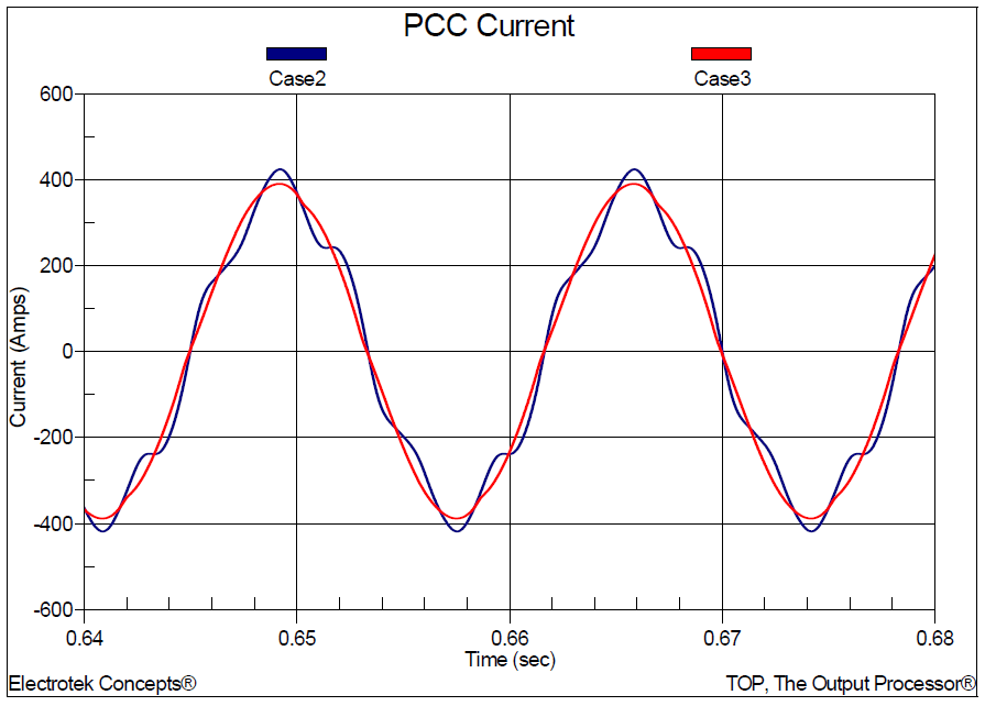
Figure 5 shows the utility point of common coupling (PCC) current for the two cases with the capacitor banks (Case #2) and harmonic filters (Case #3) in service. Converting the capacitor banks into harmonic filters reduced the current total harmonic distortion from 12.2% to 1.5%. As summarized in Table 1, the 5th harmonic PCC current was reduced from 32.1A to 3.3A when the harmonic filters were applied.
SUMMARY
This case study summarizes the results for a utility distribution feeder resonance and harmonic filter evaluation. The case study evaluated the effects of distribution capacitor banks on the frequency response characteristic and the resulting harmonic distortion levels.
The simulation results showed harmonic resonances that increase voltage distortion levels above the assumed 5% THD limitation when the utility substation and feeder capacitor banks were in service. The mitigation solution was to convert the capacitor banks into harmonic filters tuned to the 4.2nd harmonic. Adding the harmonic filter banks reduced the voltage distortion to below 2.0%.
REFERENCES
1.Power System Harmonics, IEEE Tutorial Course, 84 EH0221-2-PWR, 1984.
2.IEEE Recommended Practice for Monitoring Electric Power Quality,” IEEE Std. 1159-1995, IEEE, October 1995, ISBN: 1-55937-549-3.
3.IEEE Recommended Practices and Requirements for Harmonic Control in Electrical Power Systems, IEEE Std. 519-1992, IEEE, ISBN: 1-5593-7239-7.
RELATED STANDARDS
IEEE Std. 519-1992
IEEE Std. 1159-1995
GLOSSARY AND ACRONYMS
ASD: Adjustable-Speed Drive
CF: Crest Factor
DFT: Discreet Fourier Transform
DPF: Displacement Power Factor
PCC: Point of Common Coupling
PF: Power Factor
PWM: Pulse Width Modulation
TDD: Total Demand Distortion
THD: Total Harmonic Distortion
TPF: True Power Factor
